User and maintenance manual
EN
TSC - TDC
1
8702040 – 14/01/2019 – R.7 www.d p.it
INDEX
1 INTRODUCTION..................................................................................................................................................2
1.1 GENERAL
INFORMATION ...........................................................................................................................2
1.2 MANUFACTURER
DATA ..............................................................................................................................2
1.3 CONSULTATION
METHODS .......................................................................................................................2
1.4 PERSONNEL
QUALIFICATIONS .................................................................................................................2
1.5 PERSONAL
PROTECTION
EQUIPMENT ....................................................................................................3
1.6 IDENTIFICATION
PLATE ..............................................................................................................................3
2 SAFETY ...............................................................................................................................................................4
2.1 GENERAL
WARNINGS .................................................................................................................................4
2.2 ADDITIONAL
RISKS .....................................................................................................................................4
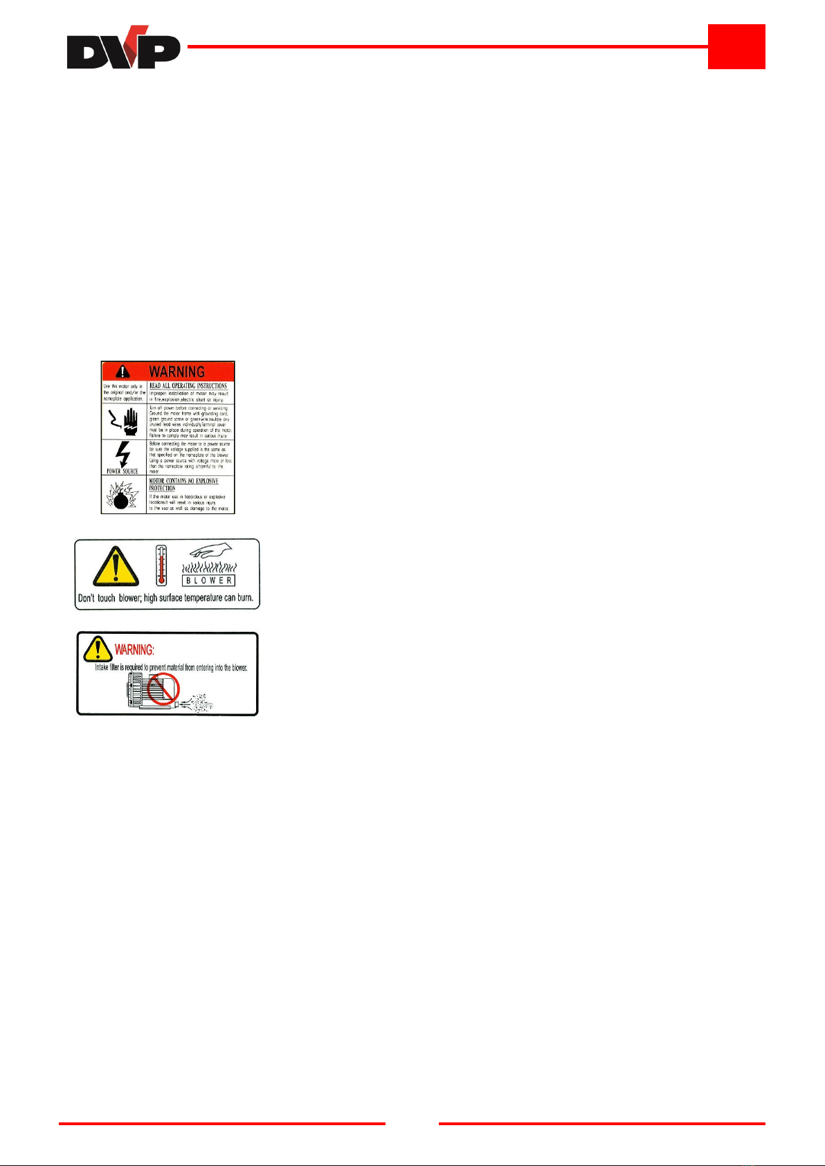
2.3 PICTOGRAMS ..............................................................................................................................................5
3 TURBINE DESCRIPTION ...................................................................................................................................6
3.1 INTENTED
USE
AND
CONTRAINDICATIONS ............................................................................................6
3.1.1 INTENTED USE ......................................................................................................................................6
3.1.2 CONTRAINDICATIONS ..........................................................................................................................6
3.2 NOISE
EMISSIONS .......................................................................................................................................6
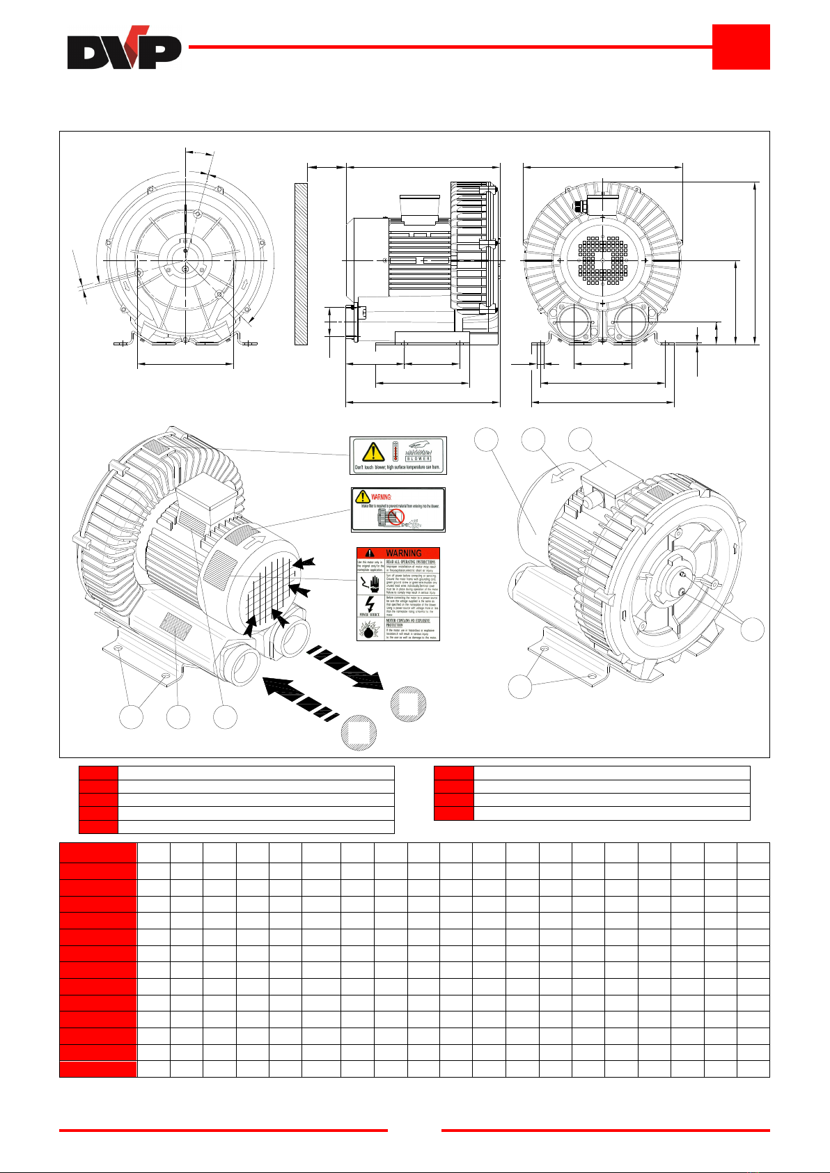
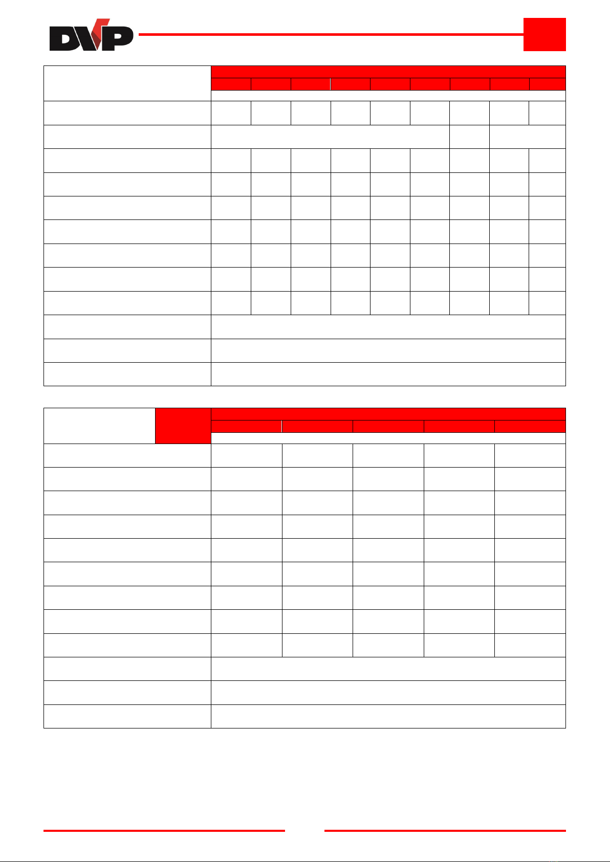
3.3 DIMENSIONS
AND
SPECIFICATIONS ........................................................................................................7
3.3.1 TSC Mod ls ............................................................................................................................................7
3.3.2 TDC Mod ls ......................................................................................................................................... 10
4 INSTALLATION ................................................................................................................................................ 13
4.1 CONTENT
RECEPTION
AND
CONTROL ................................................................................................. 13
4.2 PACKAGING .............................................................................................................................................. 13
4.3 TRANSPORT
AND
HANDLING ................................................................................................................. 13
4.4 STORAGE .................................................................................................................................................. 13
4.5 ENVIRONMENTAL
CONDITIONS ............................................................................................................. 13
4.6 TURBINE
INSTALLATION ......................................................................................................................... 14
4.7 USER
SYSTEM .......................................................................................................................................... 14
4.8 CONNECTION ........................................................................................................................................... 14
4.8.1 INTAKE AND OUTLET CONNECTION ............................................................................................... 15
4.8.2 ELECTRIC CONNECTION .................................................................................................................. 15
5 INSTRUCTIONS FOR USE .............................................................................................................................. 17
5.1 OPERATION .............................................................................................................................................. 17
5.2 START-UP .................................................................................................................................................. 17
5.3 STOP .......................................................................................................................................................... 18
5.4 DECOMMISSIONING
AND
PROLONGED
STOPPAGE ........................................................................... 18
6 MAINTENANCE................................................................................................................................................ 19
6.1 GENERAL
WARNINGS .............................................................................................................................. 19
6.2 INTERVENTION
TABLE............................................................................................................................. 20
6.2.1 INTAKE FILTER CONTROL ................................................................................................................ 20
6.2.2 REPLACING THE INTAKE FILTER .................................................................................................... 20
6.2.3 CLEANING THE MOTOR FAN PROTECTION ................................................................................... 20
6.2.4 GENERAL EXTERNAL CLEANING OF THE TURBINE ..................................................................... 20
6.2.5 CHECKING THE OPERATION OF VACUUM AND/OR PRESSURE REDUCING VALVES ............. 20
6.2.6 CLEANING THE INTAKE AND OUTLET SILENCERS ....................................................................... 21
6.2.7 GREASING THE BEARINGS .............................................................................................................. 21
6.2.8 BEARING REPLACEMENT ................................................................................................................. 21
6.3 SPARE
PARTS ........................................................................................................................................... 21
7 RETURNING THE PRODUCT .......................................................................................................................... 21
8 DISMANTLING ................................................................................................................................................. 22
9 TROUBLESHOOTING ..................................................................................................................................... 22