2
Table 2—Accessory Package Usage
BASE UNIT
ACCESSORY MODEL NUMBER
5 3 D S --- 9 0 0 --- --- --- 1 1
7
(11 5 --- 1 --- 60 )
5 3 D S --- 9 0 0 --- --- --- 1 1
8
(208/230---1---60)
Wiring Fig. No. Wiring Fig. No.
40GV C 0 0 9 --- --- --- 1 16
40GV C 0 1 2 --- --- --- 1 16
40GV C 0 1 2 --- --- --- 3 18
40GV C 0 1 8 --- --- --- 3 19
40GV C 0 2 4 --- --- --- 3 19
40GV C 0 3 6 --- --- --- 3 19
40GV M 0 0 9 --- --- --- 3 20
40GV M 0 1 2 --- --- --- 3 20
40GV M 0 1 8 --- --- --- 3 20
40GV Q009 --- --- --- 1 17
40GV Q012 --- --- --- 1 17
40GV Q012 --- --- --- 3 18
40GV Q018 --- --- --- 3 19
40GV Q024 --- --- --- 3 19
40GV Q030 --- --- --- 3 19
40GV Q036 --- --- --- 3 19
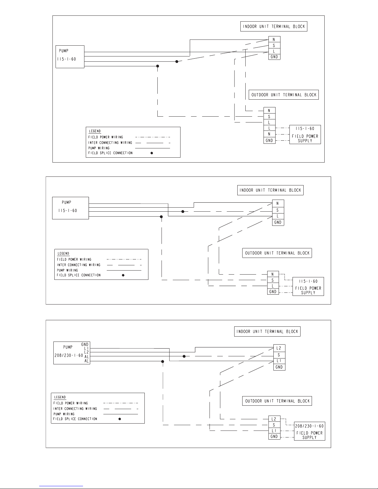
40GXC (Q) 00 9 --- --- --- 1 11
40GXC (Q) 01 2 --- --- --- 1 11
40GXC (Q) 01 8 --- --- --- 3 14 15
40GXC (Q) 02 4 --- --- --- 3 14 15
40GX M 0 0 9 --- --- --- 3 14 15
40GX M 0 1 2 --- --- --- 3 14 15
40GX M 0 1 8 --- --- --- 3 14 15
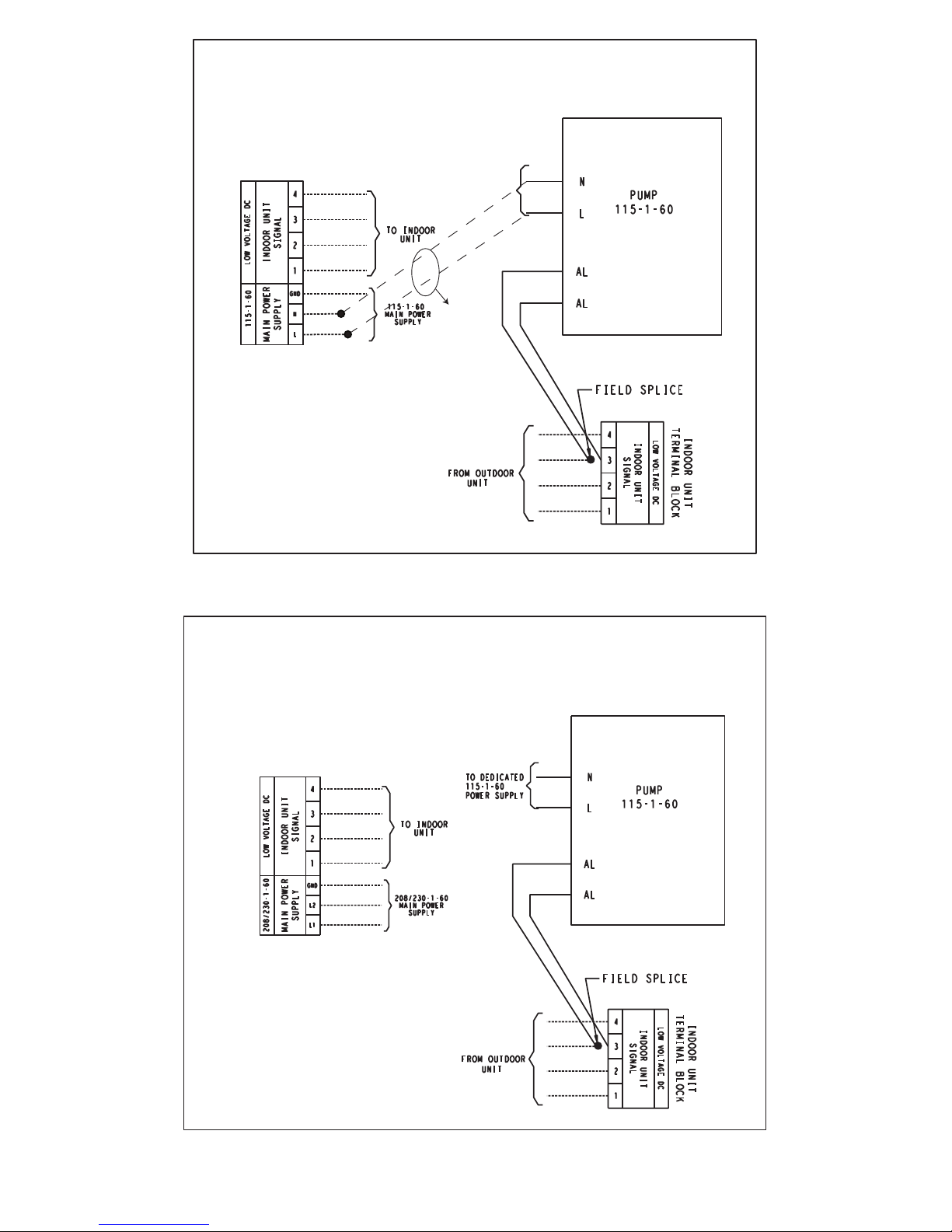
40MV C ( Q) 0 09 --- --- --- 1 8
40MV C ( Q) 0 12 --- --- --- 1 8
40MV C ( Q) 0 12 --- --- --- 3 910
40MV C ( Q) 0 18 --- --- --- 3 14 15
40MV C ( Q) 0 24 --- --- --- 3 14 15
40QN C( Q) 0 3 0 --- --- --- 3 13
40QN C( Q) 0 3 6 --- --- --- 3 13
40QNC018024--- --- ---3 12
40QN Q0 1 8 --- --- --- 3 12
40QN Q0 2 4 --- --- --- 3 12
PW3C(H)AM009 8
PW3C(H)AM012 8
PW3C(H)NM018 14 15
PW3C(H)NM024 14 15
RA S --- 09 EKC V --- UL 14 15
RA S --- 09 EK V --- U L 14 15
RA S --- 09 LK V --- U L 14 15
RA S --- 12 EKC V --- UL 14 15
RA S --- 12 EK V --- U L 14 15
RA S --- 12 LK V --- U L 14 15
RA S --- 15 EKC V --- UL 14 15
RA S --- 15 EK V --- U L 14 15
RA S --- 15 LK V --- U L 14 15
RA S --- 17 EKC V --- UL 14 15
RA S --- 17 EK V --- U L 14 15
RA S --- 17 LK V --- U L 14 15
RA S --- 22 EKC V --- UL 14 15
RA S --- 22 EK V --- U L 14 15
RA S --- 22 LK V --- U L 14 15
RAV---SP180KRT---UL 14 15
RAV---SP240KRT---UL 14 15
GENERAL
Use the two--part accessory kit (condensate pump and detection
unit) with high wall fan coils. The pump operates whenever the
condensate level in the detection unit is high enough to cause the
magnetic float switch to send a signal to start the pump.
The float switch in the detection unit also prevents overflow and
can act as a safety device by shutting down the system. The
detection unit comes with normally closed (NC) alarm contacts
(user optional, but recommended). The normally closed alarm
contact is a dry contact rated for 8 amps at 250 volts. In the event
of a problem such as a clogged drain or pump discharge line, the
alarm contact can be wired to shut down the entire system. The
condensate pump provides 10 ft (3.0 m) maximum suction lift
(A)--Fig. 2.
A12134
Fig. 2 --- Maximum Lengths
INSTALLATION
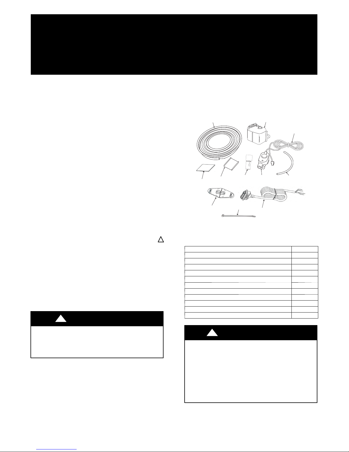
Refer to Fig. 1 and Table 1 for kit content.
NOTE: To make the installation easier, install the detection unit
assembly before installing the fan coil unit.
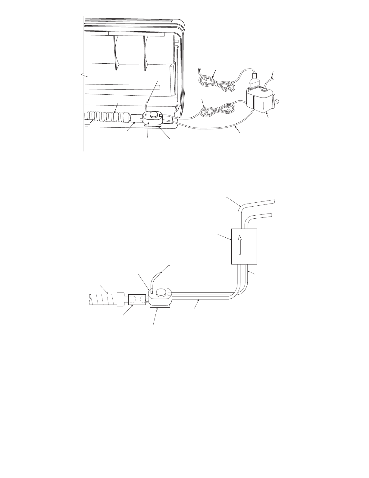
1. Unpack the contents of the condensate pump accessory
package. Attach the rubber adapter and transparent vent
tubing to the detection unit (see Fig. 6). Rubber adapter
may be cut to size if 5/8” connection is required. If 7/8”
connection to unit drain pipe is required, use rubber
adapter as shipped. Do not use a vent tube longer than
2.95” (75 mm). Slide the mounting bracket onto the bot-
tom of the detection unit. Uncoil the low voltage power
cord.
2. Remove the fan coil mounting bracket from the back of
the unit. Connect the detection unit with the rubber
adapter, to the condensate drain line (see Fig. 6).
3. Peel the adhesive cover on the back of the detection unit
mounting bracket and attach it to the inside of the unit ad-
jacent to the fan coil drain as shown in Fig. 6. Make sure
the detection is installed horizontally for proper opera-
tion of the float switch.
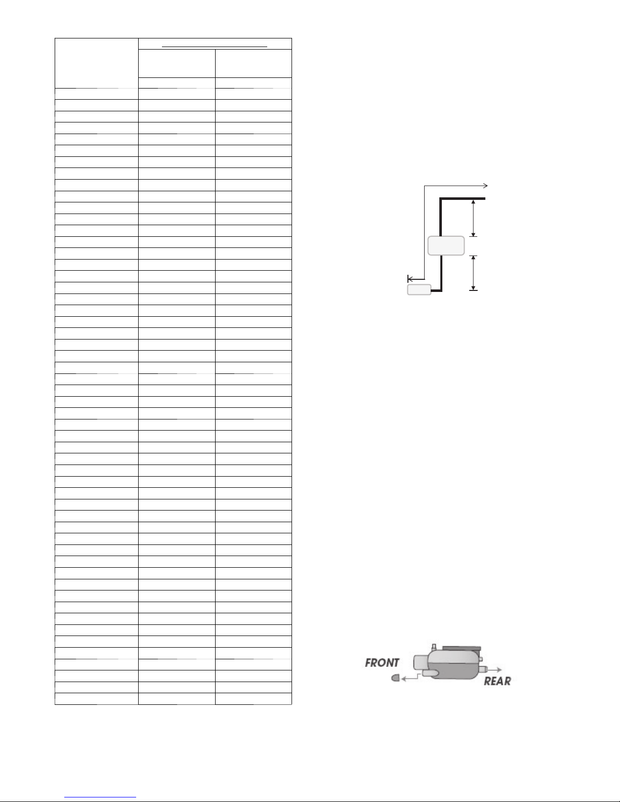
4. Attach one end of the transparent tubing to the detection
unit. The tube can be connected to either the front or the
rear as shown in Fig. 3. block the unused outlet with the
plug supplied.
A09398
Fig. 3 --- Detection Unit