Dynascan LeakVIE M016 User manual

LeakVIEW
D016-047-1
USER GUIDE
Seal Integrity & Leak Detection Systems
FOR USE WITH MODEL NUMBERS:
M016-011 (Automatic IVG - Size 1)
M016-012 (Automatic IVG - Size 2)
M016 LeakVIEW

D016-047-1 LeakVIEW User Guide Page 2 of 22
CONTACT INFORMATION
For technical assistance or servicing, in the initial instance please contact your
supplier.
Manufactured by:
Cambridge Sensotec Ltd.
29 Stephenson Road
St. Ives
Cambridgeshire
PE27 3WJ
United Kingdom
Dynascan is the leak detection brand of Cambridge Sensotec Ltd
Tel: +44 (0) 1480 462142
Email: info@dynascan.co.uk
Website: www.dynascan.co.uk
© 2018 Cambridge Sensotec Ltd. Document number D016-047-1 (Feb 2018)
SUPPLIED BY:
Serial Number:
CONTACT INFORMATION

D016-047-1 LeakVIEW User Guide Page 3 of 22
SAFETY INSTRUCTIONS
• Do not subject the test chamber to differential temperature fluctuations.
• Disconnect the power supply before opening the connection box.
• Do not allow any liquid to come in contact with any electrical component.
• The system must only be filled with water that is of a temperature not greater
than the ambient temperature as the test chamber.
• Do not subject the test chamber to shock, especially when under vacuum.
• Do not allow the test chamber to come into contact with substances that can
attack the acrylic.
• Do not allow the weight of the test chamber to rest on the drain tap.
• Do not exceed the stated air supply pressure.
• Do not exceed the stated vacuum level.
• Do not attempt to relocate the system when it is filled with liquid.
• The compressed air supply should be isolated when not in use.
• This manual should be read and understood in its entirety before installation
or operation of the LeakVIEW system.
SAFETY INSTRUCTIONS

D016-047-1 LeakVIEW User Guide Page 4 of 22
SPECIFICATIONS
CONTROLS
Control Front Panel:
Touch screen display
START Button.
STOP / RESET Button.
Run / Program key.
Power indicator.
Control Rear Panel:
Power switch.
TECHNICAL
Vacuum control range – 200 to -800 mbars.
SIZE
M016-011
External dimensions: Height = 553mm, Width = 510mm, Depth = 430mm.
Internal Test Chamber dimensions: Height = 255mm (*175mm), Width = 440mm, Depth = 310mm).
* Base to clamp plate dimension
M016-012
External dimensions: Height = 643mm, Width = 625mm, Depth = 500mm.
Internal Test Chamber dimensions: Height = 330mm (*260mm), Width = 500mm, Depth = 330mm.
Pressure Plate to Base Height = 175mm.
* Base to clamp plate dimension
CONTROLLER
External dimensions: Height = 235mm, Width = 430mm, Depth = 345mm.
WEIGHT
M016-011 = 45kg (Dry).
M016-012 = 65kg (Dry).
CONTROLLER = 7kg
OPERATING TEMPERATURE
15-40C (Storage 0-50C).
ELECTRICAL SUPPLY
230 V, 50Hz. 300 VA.
COMPRESSED AIR SUPPLY
6.5 bar (7 bar max.) 8mm Push-in connection.
Capacity : >150l/min
MANUFACTURING STANDARDS
CE Marked.
SPECIFICATIONS

D016-047-1 LeakVIEW User Guide Page 5 of 22
SPECIFICATIONS
DECLARATION OF CONFORMITY
Name of manufacturer or supplier: Cambridge Sensotec Limited
Full postal address including country of origin: 29 Stephenson Road
Saint Ives
Cambridgeshire
PE27 3WJ
United Kingdom
DECLARATION OF CONFORMITY
We Cambridge Sensotec under our sole responsibility declare that the product listed below:
Description Category: BUBBLE EMISSION PACK TESTING DEVICE (CONTROLLER)
Model Designation (s): M016-020
Serial Number: ____________
Conforms to the principle safety objectives of the European Directive 2006/95/EC by application of the following
standard: EN 61010-1:2010
Conforms to the protection requirements of European Directive 2004/108/EC by application of the following stand-
ard: EN 61326: 2006 (industrial).
Year of affixation of the CE Marking 2018
Place of issue: St. Ives
Name of authorised Representative: Mark Swetnam
Position of authorised Representative: Managing Director
Signature of authorised representative
Date 29th March 2018

D016-047-1 LeakVIEW User Guide Page 6 of 22
1.1 INTENDED USE
The LeakVIEW is a package testing system based on the Pharmaceutical industry standard Bubble
Emission test method. The unit may also be used without water, where the visible leakage of pack
contents may be observed.
The system is intended for use in laboratory and manufacturing environments.
1.2 OPERATING PRINCIPLE
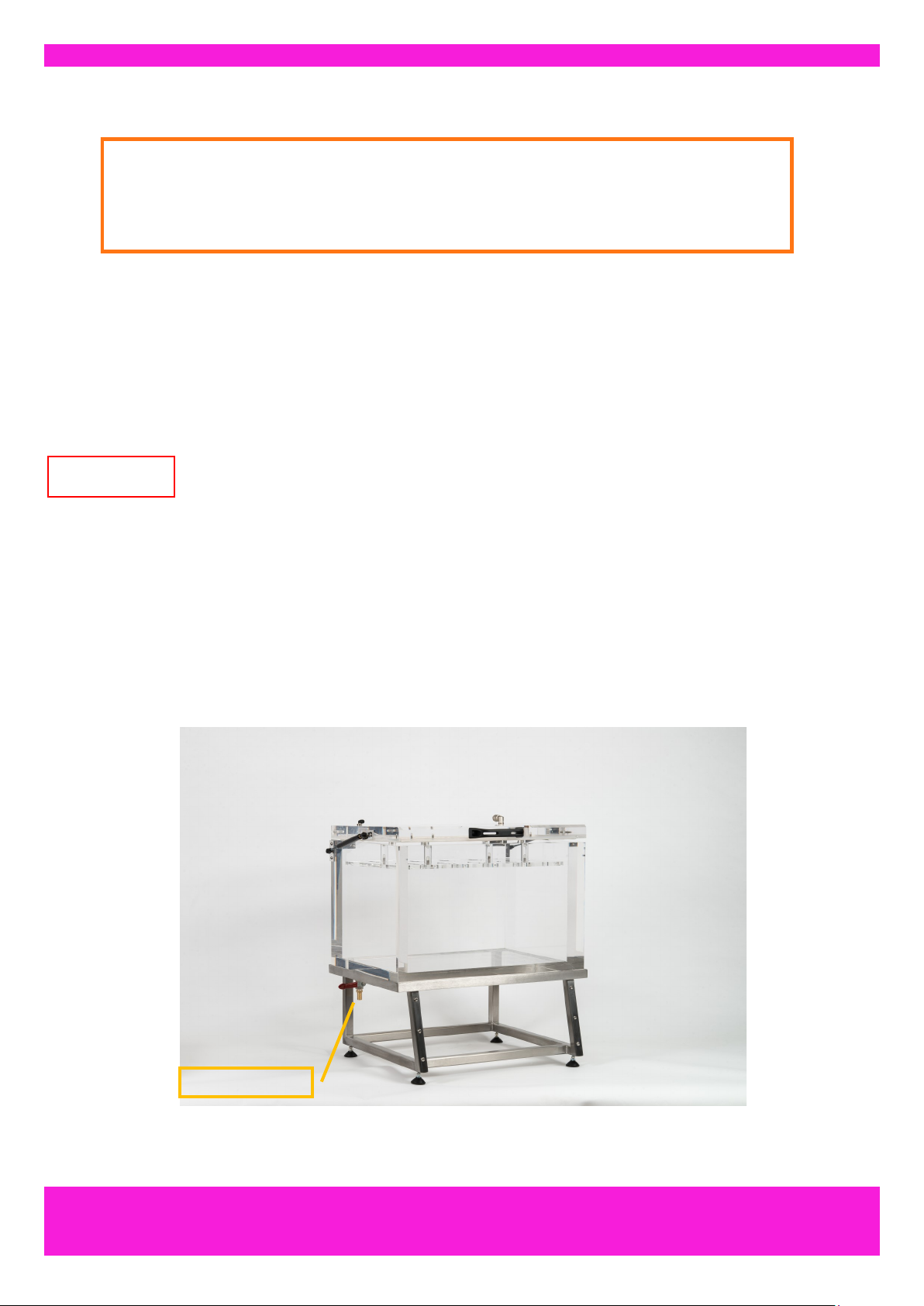
The LeakVIEW comprises a test chamber and vacuum generator controller. The vacuum and test time
may be programmed and monitored on the control panel. The test chamber is filled with water (enough
to cover the perceived range of packs when they are inflated), alternatively the test chamber may be
left empty for tests where visible pack content leakage is observed or for burst testing.
For a standard bubble emission test the following sequence takes place:
1. The packs are placed in the chamber and the lid is closed. This causes the pressure plate to
submerge the pack.
2. The operator presses the START button. This causes the air supply to the vacuum generator to
be switched on for the EVACUATION phase.
3. When the target vacuum is achieved, the vacuum generator is switched off and the system en-
ters then vacuum HOLD phase, where the vacuum will be held constant.
4. The operator observes the pack for any bubble stream due to a pin hole or seal defects.
5. When the test time has elapsed, the system enters the VENT phase and the vacuum is de-
stroyed, the lid can then be opened and the pack removed.
INTRODUCTION
SECTION 1: INTRODUCTION
This section describes:
• What the LeakVIEW unit should be used for
• The operating principle
• LeakVIEW unit features and benefits

D016-047-1 LeakVIEW User Guide Page 7 of 22
2.1 TYPOGRAPHICAL CONVENTIONS
The following conventions are used in this document:
2.2 WARNINGS, CAUTIONS AND NOTES
A WARNING indicates a potentially hazardous situation, which if not avoided may
result in injury.
A CAUTION indicates where a failure to observe an instruction or precaution could
result in equipment damage or undesirable operation.
A NOTE indicates important information that helps the operator make better use of
the equipment.
CAPITALS Status indicator names (where applicable)
BOLD CAPS Switch (switch) names (where applicable)
CONVENTIONS
SECTION 2: CONVENTIONS
This section describes:
• The typographical conventions
• Warnings, cautions and notes
WARNING
CAUTION
NOTE

D016-047-1 LeakVIEW User Guide Page 8 of 22
3.1 UNPACKING
The LeakVIEW is supplied in a packing crate that should be retained should the unit require returning
to the supplier. The crate side and top faces should be removed. The base unit should be unpacked
first and located in its final position. The test chamber can then be unpacked and placed on the base
unit. It is suggested that a small screw or bottle jack with a padded contact area is placed centrally
within the base unit. The chamber can then be lifted onto this and then lowered into position.
If the test chamber is supplied with its fittings attached, do not allow the weight of the
chamber to bare down on the drain tap fitted to the base. The test chamber is also
heavy, this may require two people to lift it. Ensure body parts are kept clear of the
base of the chamber when it is being lowered into position.
3.2 POSITIONING
The Test Chamber should be positioned, such that it is level and subjected to minimal vibration or
movement, A position that affords an all-round view would be an advantage. The supporting surface
must be able to withstand the weight of the system when filled with water. Access to the drain tap
should also be considered. The Controller Unit should be placed to one side of the Test Chamber such
that the front panel controls are in easy reach.
INSTALLATION
SECTION 3: INSTALLATION
This section describes:
• How to unpack the LeakVIEW
• Positioning of the LeakVIEW unit
Figure 3.1
CAUTION
Drain tap position.

D016-047-1 LeakVIEW User Guide Page 9 of 22
INSTALLATION
3.3 ELECTRICAL SUPPLY
The power lead (supplied) must be connected to an AC supply as specified on the rating plate located
next to the IEC power inlet connector.
This equipment must be connected to a protective earth (grounded power supply).
3.3.1 POWER SUPPLY FUSE
There is a single fuse fitted inside the fuse holder within the IEC mains connector on
the rear panel. Replace with the same specification fuse. The LeakVIEW fuse type
and rating is a T type (Anti-surge) with a 5 Amp rating. See Fig 3.2.
CAUTION
3.3.2 MAINS SWITCH
The mains switch is incorporated within the IEC mains connector. It is a rocker type switch and is la-
belled 1 for ON and 0 for OFF. It is advisable to switch the unit off when not in use (Fig 3.2).
Figure 3.2
Fuse location.

D016-047-1 LeakVIEW User Guide Page 10 of 22
INSTALLATION
3.4 PNEUMATIC SUPPLY
An air supply of 6 bar (7bar max) should be connected to the Air Supply connection port on the rear
panel. This air supply must be dry and oil free.
Ensure the air supply is connected to the correct port. Provision must be made to iso-
late the air supply in an emergency.
3.5 TEST CHAMBER CONNECTIONS
The Vacuum and Sense tubing from the test control unit should be connected to the ports on the lid of
the Test Chamber. These are push-fit couplings and are free to rotate.
WARNING
Figure 3.4
Air Supply
Vacuum Line
Sense Line
Figure 3.3
Example of a push-fit connection.

D016-047-1 LeakVIEW User Guide Page 11 of 22
INSTALLATION
Figure 3.5
The drain tap should be orientated as
shown. The handle is in the OFF position.
3.6 THE DRAIN TAP
When the test chamber has been located on the base unit, the drain tap should be fitted. Apply PTFE
tape to the tap tread and screw this into the treaded hole located in the base of the chamber. This
should be done by hand so as not to damage the tread by over-tightening. A right angle fitting is
included for optional use if required. Figure 3.5 indicates the suggested orientation of the tap (with right
angle fitting). A suitable length of hose should be attached to the barb. If the hose is to be removed,
take care not to rotate the fittings as this may disturb the seal. If this does occur the fitting should be
removed and the seal remade with PTFE tape.
Do not over-tighten the drain tap, doing so may result in the test chamber thread being
damaged. If the test chamber is to be separated from the base, the drain tap should be
removed.
CAUTION

D016-047-1 LeakVIEW User Guide Page 12 of 22
4.1 USER CONTROLS
TOUCH SCREEN DISPLAY – This combined control function is divided into three sectors:
KEY SWITCH - Moving to this sector initially activates the vacuum generator. Moving further into the
sector increases the evacuation rate. The key may be removed to lock the system in the selected
mode.
START BUTTON - Moving to this sector holds the vacuum at the desired level and deactivates the
vacuum
generator.
RESET BUTTON - Moving to this sector vents the vacuum (air is re-admitted to the test chamber),
moving further into the sector increases the vent rate.
LEAKVIEW DESCRIPTION
SECTION 4: LEAKVIEW DESCRIPTION
This section describes:
• The user control
• Indicator
Figure 4.1

D016-047-1 LeakVIEW User Guide Page 13 of 22
LEAKVIEW OPERATION
SECTION 5: LEAKVIEW OPERATION
This section describes:
• Prepare the LeakVIEW for use
• How to load the product into the test chamber
• Running a Vacuum Test
5.1 PREPARATION
This section describes the routine operation for production operators.
1. Ensure the system is connected to the air supply. Set supply regulator to 6.5bar (7 bar max).
2. The test chamber should be filled with water. This should be to a level that covers the top of the
pressure plate when the pack has expanded, but is within 3cm of the chamber opening. The
water level may need to be adjusted to accommodate a wide range of pack volumes. See figure
5.1.
The water temperature should not exceed the ambient temperature of the test
chamber.
CAUTION
Figure 5.1
Water level should cover the
pressure plate when pack has
expanded under vacuum.
3. Switch on the power at the rear of the Control Unit.
4. After a few seconds the control software will load. The system will display INITIALISING in the
Test Status indicator.
5. After a short time the system will display READY in the Test Status indicator.

D016-047-1 LeakVIEW User Guide Page 14 of 22
5.2 SYSTEM OPERATION - TEST METHOD PROGRAMMING
Refer to Section 6 regarding test method development.
1. Ensure the POWER switch is in the ON position.
2. The Key switch should be turned to the ‘Program’ position to allow the supervisor to set the re-
quired test parameters from within the Program screen. See fig 5.3.
LEAKVIEW OPERATION
Figure 5.3
1. The supervisor will need to enter the following 3 test settings. Touching on a parameter will open
a virtual keyboard (or a physical one may be connected to a USB socket if preferred).
2. The Target Vacuum level in millibars. A usable range is 200 - 800 mbars.
Do not exceed a vacuum level of 800mbars
3. The total Test Time in seconds. This is the time the vacuum is held constant.
4. An Evacuation Timeout in seconds. This is the time allowed for the vacuum to be created before
an error is posted and the test aborted. It prevents the system continually evacuating air under a
leak condition (e.g. the lid is not closed).
5. To aid test method development, during the parameter setting process, the START button may
be pressed to initiate a test cycle. The measured values will then be displayed.
6. Click the SAVE button to save your new settings. The system will store these settings when the
system is powered down.
7. The system may be operated in Program mode or set to Run mode (and the key removed) for
security.
CAUTION
Parameter set-
point values.
Increment /
Decrement
keys.
Measured val-
ues.

D016-047-1 LeakVIEW User Guide Page 15 of 22
LEAKVIEW OPERATION
5.3 SYSTEM OPERATION - VACUUM BUBBLE EMISSION TEST
Refer to Section 5.1 regarding test method programming.
1. Ensure the POWER switch is in the ON position.
2. The Key-switch should be in the Run position. The Run Mode screen will be displayed. Fig 5.4
3. Open the test chamber lid.
4. Place the pack into the water.
5. Close the lid. Take care not to displace the water over the edge of the chamber.
6. Press The START button , hold the lid down for a few seconds to make sure the test chamber
sealed air-tight, this is to allow a vacuum to start forming in the test chamber. (Pressing the RE-
SET button will abort the test cycle).
Figure 5.4

D016-047-1 LeakVIEW User Guide Page 16 of 22
LEAKVIEW OPERATION
5.3.1 THE TEST PHASE
The system will execute the following test phase:
Evacuation
1. The system will start evacuating the tank until it reaches the specified ‘target vacuum’.
During this stage the Test Status indicator will display EVACUATING or SLOW EVACUATING,
and a timer will also start counting towards a limit as set in the Evacuation Timeout parameter.
If for any reason the Vacuum generator does not manage to fully evacuate the tank before the
Evacuation Timeout ends then the system will stop the evacuation process and return to the
READY state.
The Live Vacuum reading is displayed under the Target Vacuum parameter, this reading will
increase during the evacuation stage until it closely matches the ‘Target Vacuum’ setting .
Main test in progress
2. Once the target vacuum has been reached , the system will hold the vacuum at that level for the du-
ration set in the Test time setting and the Test Status indicator will display MAIN TEST IN PRO-
GRESS.
During this phase, If the vacuum level drops below 98% of the target vacuum level the vacuum
generator will start and the system will restore the vacuum level by pulse-evacuating the test
chamber.
End of test
3. At the end of the test time period the system will release the vacuum in the test chamber by allowing
air to pass back into the chamber, at the same time the Test Status indicator will display’ VENT-
ING ....PLEASE WAIT’
After the venting is complete, the Test Status indicator will display READY and is now ready for
the next test.
5.3.2 RESETTING THE SYSTEM
The system can be reset at any time during a test by pressing the RESET button. When the RESET
button is activated, the system will abort a test and immediately move on to the Venting stage, during
this stage the system will release the vacuum in the tank by allowing air to pass back into the tank , the
test status indicator will display VENTING ....PLEASE WAIT
Once the venting process is completed and the pressure in the tank has returned to normal atmospheric
levels, the Test Status indicator will display READY and is now ready for the next test.
5.3.3 LEAK DETECTION
When the test cycle is being executed the pack should be examined for signs of bubble emission (or
even failure).
It is sometimes the case that a bubble stream is only emitted when the vacuum is
increasing. In these cases, particular attention should be paid to observing likely leak
sites during the Evacuation Phase.
NOTE

D016-047-1 LeakVIEW User Guide Page 17 of 22
5.3 SYSTEM OPERATION - ALTITUDE SIMULATION
5.3.2 ALTITUDE SIMULATION PRINCIPLE
Where packs are likely to be shipped at an elevated altitude it is of benefit to determine if the pack
material and manufacturing process are satisfactory and that the pack can withstand the stress.
Subjecting the pack to a simulated altitude of 9000Ft (for ground) or 16,000Ft (for pressurised air)
transportation should be considered. The LeakVIEW system can be employed to apply the stresses
generated by the change in pressure due to a change in altitude.
For full altitude (cycle) simulation the LeakVIEW M016-013 or M016-014 systems are
available.
LEAKVIEW OPERATION
NOTE

D016-047-1 LeakVIEW User Guide Page 18 of 22
5.3.3 ALTITUDE SIMULATION TEST METHOD
1. To reduce the evacuation time insert the optional infills (part P016-026). These reduce the test
chamber dead volume. Ensure that there is enough space between the top of the infill and the
pressure plate to allow the pack to fully expand.
2. A catch-tray should be placed in the test chamber to contain any product spillage.
3. Place the pack onto the top of the infill (or onto the catch-tray)
4. Close the lid.
5. Rotate the control Lever towards the EVACUATE position. When the lever enters the quadrant
the air supply will be switched on. Rotating the lever through the quadrant varies the evacuation
rate. A gradual evacuation rate is recommended to aid observation.
6. As the vacuum is increasing observe the pack for any failure.
7. When the required vacuum level has been attained move the control lever to the HOLD position.
Refer to table 5.3.3.1 for the vacuum to altitude relationship.
8. The vacuum should be maintained for the period specified by the Test Protocol being employed.
It may be necessary to apply vacuum from time to time to compensate for natural vacuum decay.
9. When the test is complete move the Control Lever to the VENT position.
10. When the vacuum has been destroyed the lid may be opened and the pack removed.
11. The pack should be examined for any distress or failure.
Table 5.1 shows the relationship of vacuum to altitude. Alternatively the formula below gives an
approximation of the relationship.
.
LEAKVIEW OPERATION
Where:
P = Measured pressure.
Po = Pressure at sea level.
h = Measured height.
ho = Height of atmosphere
V = Vacuum
P=Poe-(h/ho)
Or
V=1013.25-P

D016-047-1 LeakVIEW User Guide Page 19 of 22
5.2.3 ALTITUDE SIMULATION TESTING - ALTITUDE TO VACUUM RELATIONSHIP
LEAKVIEW OPERATION
Table 5.1: The relationship of vacuum to altitude.

D016-047-1 LeakVIEW User Guide Page 20 of 22
6.4 ROUTINE MAINTENANCE
6.4.1 CHANGING WATER
Over time water may become contaminated. When this occurs the water should be changed.
1. Connect the drain hose to the Drain Valve.
2. Place the open end of the pipe in a container of sufficient size to contain the test chamber
contents (25l to 45l) of liquid.
3. Open the drain valve and drain the chamber.
4. Clean the chamber with diluted solution of detergent and cold water.
5. Close the drain valve and remove the drain hose.
6. Refill the chamber with water that is of the same temperature or less than the ambient chamber
temperature.
6.4.2 LID SEAL REPLACEMENT
Should the lid become damage, this should be replace by using the lid seal kit. Part no. A016-030.
This contains the required parts and instructions for fitting.
6.4.3 CLEANING
The LeakVIEW unit may be cleaned a dilute solution of detergent and cold water.
Do not use any solvents such as methylated spirits, turpentine, white spirit or
proprietary window cleaning products. To avoid abrading the surface use a chamois or
soft cloth.
MAINTENANCE
This section describes:
• Routine maintenace
• User serviceable parts
• Cleaning
• Calibration
• Troubleshooting
• Repairs
SECTION 6: MAINTENANCE
CAUTION
This manual suits for next models
2
Table of contents
Popular Scanner manuals by other brands

Epson
Epson 1250 - Perfection Photo Flatbed Scanner Setup guide

GE
GE LightSpeed 16 Product data sheet

REED
REED R8008 instruction manual

Colortrac
Colortrac SmartLF Cx Series instruction manual

Zircon
Zircon SuperScan K4 user manual

WizCom Technologies
WizCom Technologies Readingpen Basic Edition K-12 quick start