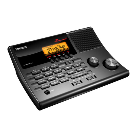
PROEL MS 32 User manual

PROEL
MS 32
PROGRAMMABLE
MIDI SENDER
OWNER’S
MANUAL

2Proel MS 32 Owner's Manual
INDEX
SPECIFICATIONS....................................................................................................................... 3
MEMORY STRUCTURE............................................................................................................ 4
MS 32 FRONT AND REAR VIEW ............................................................................................. 5
POWER ON.................................................................................................................................. 6
GLOBAL PARAMETERS........................................................................................................... 7
POWER-ON NAME :..............................................................................................................................................7
POWER-ON SET & PATCH RECALL : .................................................................................................................8
BASIC RX MIDI CHANNEL :................................................................................................................................9
FOOT CONTROLLER 1 CALIBRATION :...........................................................................................................10
FOOT CONTROLLER 2 CALIBRATION :...........................................................................................................11
CONTINUE SWITCH ASSIGNMENT:.................................................................................................................12
GLOBAL PARAMETERS FLOW CHART : .........................................................................................................13
WRITE GLOBAL PARAMETER:.........................................................................................................................14
MODE......................................................................................................................................... 15
SET MODE................................................................................................................................. 16
SET SELECTION (0~9): .......................................................................................................................................16
START/STOP AND CONTINUE FUNCTIONS:...................................................................................................17
NOTE:...................................................................................................................................................................17
SET NAME :........................................................................................................................................................19
SONG SELECT :...................................................................................................................................................20
"A" PART TX MIDI CHANNEL :.........................................................................................................................21
"B" PART TX MIDI CHANNEL : .........................................................................................................................22
SET PARAMETERS FLOW CHART:...................................................................................................................23
WRITE SET MEMORY: .......................................................................................................................................24
PATCH MODE........................................................................................................................... 25
0~9 PATCH SELECTION:....................................................................................................................................25
START/STOP AND CONTINUE FUNCTIONS:..................................................................................................26
EDIT PATCH PARAMETERS:.............................................................................................................................27
FC1 ASSIGN :.......................................................................................................................................................28
FC1 RANGE : .......................................................................................................................................................29
FC2 ASSIGN :.......................................................................................................................................................30
FC2 RANGE : .......................................................................................................................................................31
FC 1/2 LINK :........................................................................................................................................................32
PATCH BAY SWITCH 1-2 : .................................................................................................................................33
PATCH BAY SWITCH 3-4 : .................................................................................................................................34
A CHANNEL BANK SELECT CC00 & CC32 : ....................................................................................................35
A CHANNEL PROGRAM CHANGE :..................................................................................................................36
A CHANNEL PROGRAMMABLE "x" CONTROL CHANGE :............................................................................37
A CHANNEL PROGRAMMABLE "y" CONTROL CHANGE :............................................................................38
B CHANNEL BANK SELECT CC00 & CC32 : ....................................................................................................39
B CHANNEL PROGRAM CHANGE :..................................................................................................................40
B CHANNEL PROGRAMMABLE "x" CONTROL CHANGE :............................................................................41
B CHANNEL PROGRAMMABLE "y" CONTROL CHANGE :............................................................................42
PATCH PARAMETERS FLOW CHART:.............................................................................................................43
WRITE PATCH MEMORY:..................................................................................................................................44
FACTORY RESET & MIDI DATA DUMP.............................................................................. 45
FACTORY RESET:...............................................................................................................................................46
DATA MIDI DUMP (sending):..............................................................................................................................47
DATA MIDI DUMP (receiving): ...........................................................................................................................48
FREE MODE.............................................................................................................................. 49
MESSAGE SELECTION.......................................................................................................................................49
THE POSSIBLE MIDI MESSAGES:.....................................................................................................................50
MIDI MESSAGE TRANSMISSION:.....................................................................................................................52
MIDI CHANNEL/ PATCH BAY SWITCHES.......................................................................................................53
FACTORY SETUP & RANGE.................................................................................................. 54
GLOBAL PARAMETERS.....................................................................................................................................54
SET PARAMETERS .............................................................................................................................................54
PATCH PARAMETERS.......................................................................................................................................54
TECHNICAL SPECIFICATIONS............................................................................................ 55
SPARE PARTS & OPTIONALS............................................................................................... 56

Proel MS 32 Owner's Manual 3
SPECIFICATIONS
Rear Panel I/O & switch :
MIDI In
MIDI Out with Phantom Power
MIDI Thru
Foot Controller 1 In (FC 1 In)
Foot Controller 2 In (FC 2 In
Patch Bay Switch 1 Out (PBS 1 Out)
Patch Bay Switch 2 Out (PBS 2 Out)
Patch Bay Switch 3 Out (PBS 3 Out)
Patch Bay Switch 4 Out (PBS 4 Out)
DC In
16 Switches, 3 Led
Display :
LCD 16 x 1
Mode :
Free
Patch
Set
Memory structure : (1 global, 10 sets, 100 patches)
Global parameter:
1. Power On 10 characters name
2. Power On Set and Patch Number
3. RX Basic Midi Channel for Set and Patch recall Program Changes
4. Foot Controller 1 min/max calibrate
5. Foot Controller 2 min/max calibrate
6. Continue switch assign
10 Sets
each containing:
1. 10 characters name
2. Song select to be sent (0~127/Off)
3. "A" part Midi Channel (1~16)
4. "B" part Midi Channel (1~16)
5. 10 Patches to be recalled
100 Patches
10 for each Set containing 2 parts (A,B) midi data:
1.
FC 1 assign to CC (0~120 on channel A/B,AB, Off with min and max value)
2.
FC 2 assign to CC (0~120 on channel A/B AB, Off with min and max value)
3.
FC1/2 link (On/Off)
4.
PBS 1-2-3-4 closed or opened (On/Off)
5.
"A"- CC 00 (0~127/Off)
6.
"A"- CC 32 (0~127/Off)
7.
"A"- PC (1~128/Off)
8.
"A"- xCC (0~120 at value 0~127/Off)
9.
"A"- yCC (0~120 at value 0~127/Off)
10.
"B"- CC 00 (0~127/Off)
11.
"B"- CC 32 (0~127/Off)
12.
"B"- PC (1~128/Off)
13.
"B"- xCC (0~120 at value 0~127/Off)
14.
"B"- yCC (0~120 at value 0~127/Off

4Proel MS 32 Owner's Manual
MEMORY STRUCTURE
SET 0
SET 1
SET 9
Set name
Song select
"A" Midi Channel
"B" Midi Channel
10 Patches
621* 6(/(&7 )
"0~127/Off"
PATCH 0
PATCH 1
PATCH 9
"A"-CC 00
"A"-CC 32
"A"-PC
"A"- xCC
"A"- yCC
7(1 &+$5$&7(56
"SET NAME"
$ SDUW && 06% 7RQH %DQN
"0~127/Off"
$ SDUW && /6% 7RQH %DQN
"0~127/Off"
$ SDUW 3& 1XPEHUV
"1~128/Off"
$ SDUW ;&& DVVLJQ WR &RQWURO &KDQJH
"0~120"
$ SDUW ;&& YDOXH
"0~127/Off"
$ SDUW <&& DVVLJQ WR &RQWURO &KDQJH
"0~120"
)RRW &RQWUROOHU DVVLJQ WR &&
"0~120,A/B,AB
f
)& PLQ YDO
"0~127 (16 values) "
3DWFK %D\ 6ZLWFK
"On/Off"
3DWFK %D\ 6ZLWFK
"On/Off"
SET PARAMETERS
PATCH PARAMETERS
32:(521 6(7 3$7&+ 5(&$//
"0~9,0~9"
5; %$6,& 0,', &+$11(/
"1~16/Off"
7(1 &+$5$&7(56
"POWER-ON NAME"
GLOBAL PARAMETERS
$ SDUW 7; 0LGL &KDQQHO
"1~16"
% SDUW 7; 0LGL &KDQQHO
"1~16"
"B"-CC 00
"B"-CC 32
"B"-PC
"B"- xCC
"B"- yCC
FC1
FC2
PBS1
PBS2
PBS3
PBS4
)& PD[ YDO
"127~0 (16 values)"
)RRW &RQWUROOHU DVVLJQ WR &&
"0~120,A/B,AB
)& PLQ YDO
"0~127 (16 values) "
)& PD[ YDO
"127~0 (16 values)"
% SDUW 3& 1XPEHUV
"1~128/Off"
% SDUW ;&& DVVLJQ WR &RQWURO &KDQJH
"0~120"
% SDUW ;&& ;; YDOXH
"0~127/Off"
% SDUW <&& DVVLJQ WR &RQWURO &KDQJH
"0~120"
% SDUW && 06% 7RQH %DQN
"0~127/Off"
% SDUW && /6% 7RQH %DQN
"0~127/Off"
3DWFK %D\ 6ZLWFK
"On/Off"
3DWFK %D\ 6ZLWFK
"On/Off"
)RRW &RQWUROOHU
"min/max calibrate"
)RRW &RQWUROOHU
"min/max calibrate"
&RQWLQXH DVVLJQPHQW
"Cnt,PBS,Cnt+PBS"
)& OLQN
"on/off"
$ SDUW <&& YDOXH
"0~127/Off"
% SDUW <&& YDOXH
"0~127/Off"

Proel MS 32 Owner's Manual 5
MS 32 FRONT AND REAR VIEW
DC IN 9V FC2 FC1 PB4 PB3 PB2 PB1 THRU OUT IN
LCD CONTRAST
MIDI

6Proel MS 32 Owner's Manual
POWER ON
When switched on the MS32 displays 3 subsequent screen shots before displaying the MASTER
screen shot;
first screen shot:
second screen shot:
third screen shot:
MASTER screen shot in the Patch mode:
PROEL MIDISender
MS-32 User Name
00 Basic Ch = 16
0 *FACTORY0* >0

Proel MS 32 Owner's Manual 7
GLOBAL PARAMETERS
-10 characters name,
-SET and PATCH numbers displayed at power on
-the midi Basic channel and
-the calibrations for the Foot Controllers 1 and 2
-the assignment of the CONTINUE switch can be programmed as follows:
Power on the MS32 by keeping the "SELECT/CHANNEL" switch pressed; as soon as the stored
name is displayed, release the "SELECT/CHANNEL" switch;
POWER-ON NAME :
The "10
" and "10
" switches (
Æ
Æ
)
allow you to choose the character to be
inserted.
(Keeping the switch pressed the characters
will shift automatically).
Use the "
5" and "6
" switches (
Æ
Æ
)
***User Name ***
Character Cursor
***User Name ***

8Proel MS 32 Owner's Manual
Press and release:
-the "CCXXX/CONTINUE" switch (
Æ
Æ
) to confirm the data and pass to the
display/modification of the following "GLOBAL" parameter or
-the "SELECT/CHANNEL" switch (
Æ
Æ
) to confirm the data and exit from "GLOBAL" parameter
programming.
POWER-ON SET & PATCH RECALL :
Press the "10
" and "10
" switches (
Æ
Æ
)
to choose the value (from 0 to 9) to be
inserted. (Keeping the switch pressed the
characters will shift automatically).
Use the "
5" and "6
" switches (
Æ
Æ
)
to move the cursor from SET to PATCH.
SET 0 & PATCH 0
SET 0 & PATCH 0
Value Cursor

Proel MS 32 Owner's Manual 9
Press and release:
-the "CCXXX/CONTINUE" switch (
Æ
Æ
) to confirm the data and pass to the
display/modification of the following "GLOBAL" parameter or
-the "SELECT/CHANNEL" switch (
Æ
Æ
) to confirm the data and exit from "GLOBAL" parameter
programming.
BASIC RX MIDI CHANNEL :
Press the "10
" and "10
"switches (
Æ
Æ
)
to choose the value (from 1 to 16 or AL =
Omni On) to be inserted and the On/Of
f
condition. (Keeping the switch pressed the
characters will shift automatically).
Use the "
5" and "6
" switches (
Æ
Æ
)
to move the cursor from channel number to
On/Off
Basic RxCh 16 On
Basic RxCh 16 On
Value Cursor

10 Proel MS 32 Owner's Manual
Press and release:
-the "CCXXX/CONTINUE" switch (
Æ
Æ
) to confirm the data and pass to the
display/modification of the following "GLOBAL" parameter or
-the "SELECT/CHANNEL" switch (
Æ
Æ
) to confirm the data and exit from "GLOBAL" parameter
programming.
FOOT CONTROLLER 1 CALIBRATION :
FC1 mn -- Mx --
Position the Foot Pedal inserted in the FC1
socket at minimum value and press the
START/STOP switch;
Position the Foot Pedal at maximum value
and press the START/STOP switch (
Æ
Æ
).
OK is displayed twice on the screen.
FC1 mn Ok Mx Ok
Table of contents
