3
SAFETY RULES AND WARNINGS
If there is a natural gas smell;
Shut off the gas valve of the appliance and all of your gas burning appliance
Shut off and put out your oven, stove, cooker etc.
Do not light matches, lighters etc, put out your cigarettes.
Open all your windows and door and ventilate the room.
Do not switch on your electrical devices and do not touch the plugs.
Shut off the gas valves at the building entrances.
Do not use phones in the environments that have a gas smell.
Call the gas company and inform the closest technical service.
Do not put or use flammable materials near your appliance.
Keep materials like water, foam etc. away from electrical connections during cleanup, maintenance etc.
Do not block ventilation outlets in your boiler room.
INSTALLATION
Installation of the Systyem
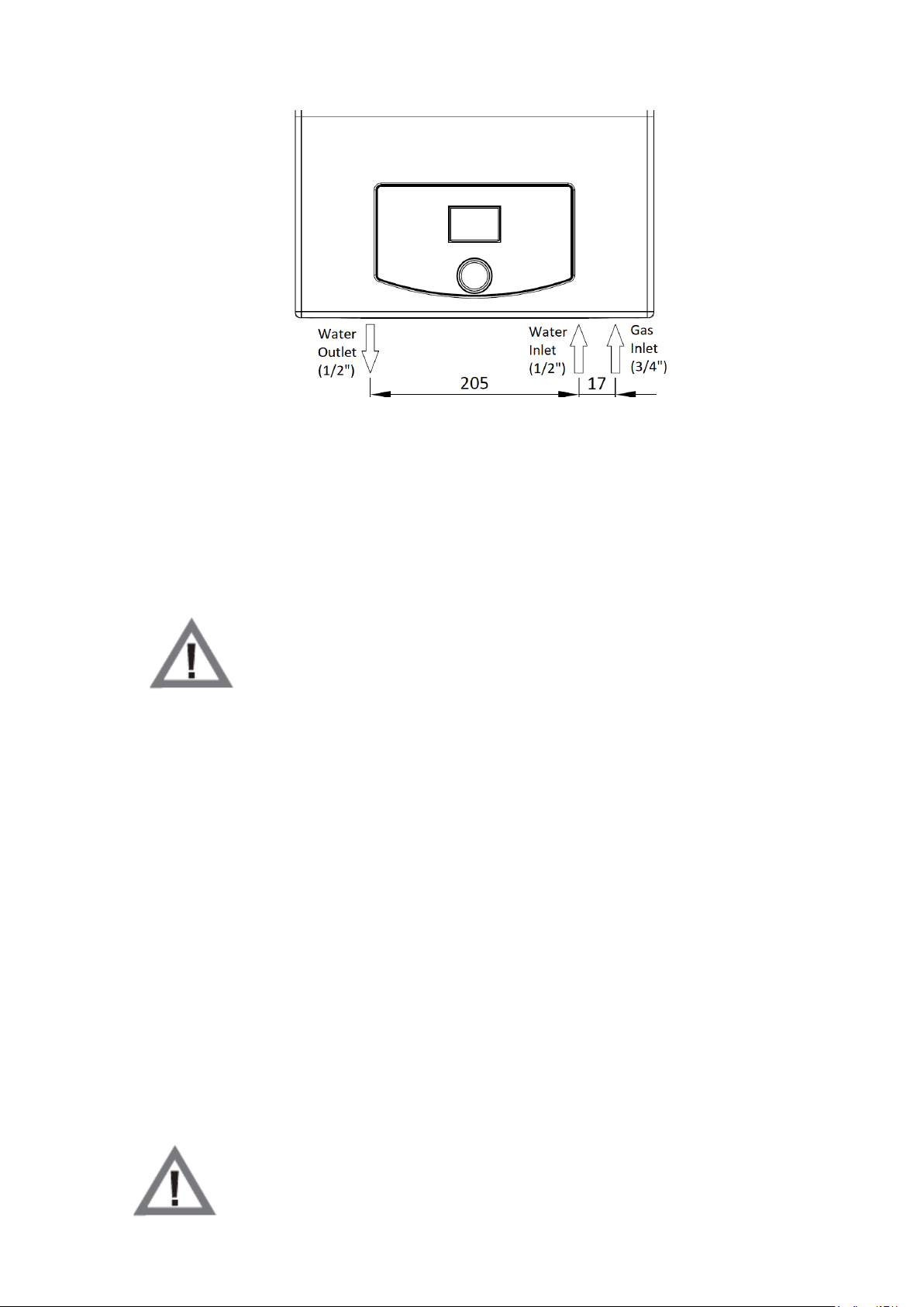
• Before the installation of your gas water heater, natural gas and domestic hot water pipings must be ready.
Natural gas pipings must be designed, approved and done by a qualified engineering office. All these must be
done and paid by the user.
•The appliance must be connected to a grounded plug with 230V AC, 50 Hz supply.
• Any dirt, blockages, welding residuals, burr, flug etc. particules left inside the pipes will affect the gas water
heater’s performance. These residuals will cause gas water heater to overheat, noisy operating etc. Any
damage or failure caused by unfit piping system is out of warranty coverage.
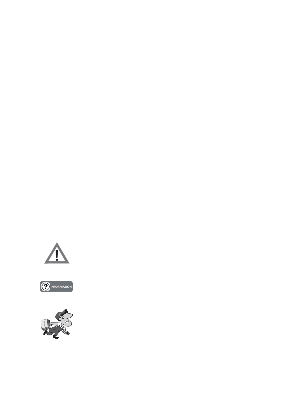
Installation of Gas Water Heater
•Installation of this gas water heater must be done by a authorized technical service according to the
information (placement, flue connections etc.) presented by the standartds and authorized gas companies.
After the installation, installer must make sure that user has given the user manual and give all the necessary
information about the boiler and related safety equipments.
•Gas water heater must be installed in a manner that the appliance should not be in direct contact with water
vapor, detergent vapor or similar chemicals.
•Flue connections must not be tampered with without consulting to the authorized technical service.
The appliance will not be in use until winter season, water inside the gas water
heater should be drained to prevent freezing.
The appliance should not be used above 2000m altitude above sea level.
Do not install the appliance where it will be affected by direct sunlight. Sun beams
can cause discoloration on the outer surfaces of the appliance.
COMISSIONING
•Start-up of the appliance must be done by the authorized service. Natural gas usage must be approved by the
related gas company prior to the start-up.
•The gas type (natural gas), inlet gas pressure (mbar), maximum water pressure (bar) and electrical nominal
voltage (V) values on the information label must be checked with the local conditions.
• After the installation of the appliance, please ask your authorized service personnel to give information about
the operation and safety equipments of the appliance.