E-gas JSD 12 E Guide

INSTRUCTIONS FOR
THE INSTALLATION AND MAINTENANCE
OF HOUSEHOLD INSTANTANEOUS INDOOR
LPG GAS WATER HEATER
TYPE B
(VENT-PIPE)
Model No: JSD 12 E
LPGSASA
Permit No: _______
E–Gas Systems: The Proven Preferred Choice

CONTENTS
1.IMPORTANTNOTESANDPRECAUTIONSFORUSE1
2.DESCRIPTIONOFTHEAPPLIANCE2
2.1PerformanceLayout2
2.2MainTechnicalData&Features3
2.3DescriptionofControlFunctions3
3.INSTRUCTIONSFORTHEINSTALLER4
3.1TechnicalInformation4
3.2Installation4
3.3Howtoinstall5
3.4Theperformanceofventpipeanti‐blockdevice7
3.5RepairandMaintenance7
4.INSTRUCTIONSFORTHEUSER8
4.1Operation8
4.2NOTESONSAFETY8
5.INSTRUCTIONSFORTHEUSER:CLEANINGANDMAINTENANCE10
5.1Cleaning10
5.2Maintenance10
6.WHATTODOIF…11
7.TROUBLESHOOTING12
7.1MaintenanceandRepairGuidetoCommonMalfunctions12
TECHNICALASSISTANCEANDSPAREPARTS13
8.CONTACTDETAILS13
1
1. IMPORTANT NOTES AND PRECAUTIONS FOR USE
You have purchased one of our products for which we
thank you. We are confident that this new appliance,
modern, functional and practical, made with top
quality materials, will meet all your requirements.
This new appliance is easy to use but before installing
and using it, it is important to read this handbook
through carefully. It provides information for a safe
installation, use and maintenance. Keep this
handbook in a safe place for future reference.
The manufacturer reserves the right to make all the
modifications to its products that it deems necessary
or useful, also in your interests, without prejudicing its
essential functional and safety characteristics.
The manufacturer cannot be held responsible for any
inaccuracies due to printing or transcription
errors that may be found in this handbook.
N.B.: the pictures shown in the figures in this
handbook are purely indicative...
•This unit was designed for LP Gas at an
operating pressure of 2.8 kPa.
•A suitable approved LPG regulator that
complies with the requirements of SANS 1237
must be installed
•The installation, adjustments and maintenance
jobs must only be carried out by qualified and
registered installer, and that this installation
must comply with the requirements of SANS
10087-1.
•The manufacturer cannot be held responsible for
any harm to people or damage to things deriving
from an incorrect installation or maintenance or
from an erroneous use of the appliance. The
supplier expressly absolves itself from any
damage or injury resulting from system use.
Once the outer wrapping and the inner wrappings of
the various parts have been removed, check and
make sure that the appliance is in perfect condition. If
you have any doubts do not use the appliance and
call in a qualified person.
•The packaging materials used (cardboard, bags,
polystyrene foam, nails, etc.) must not be left
anywhere in easy reach of children because they
are a potential hazard source. To safeguard the
environment all packaging materials are
environment friendly and recyclable.
•Prior to connecting the appliance ensure that the
rating plate data corresponds to that of the gas
supply.
•This Type B instantaneous gas water geyser
must be fitted with a secondary flue.
•Proper ventilation is vital for the efficient
performance of all gas appliances, as well as for
the safety of the occupants in the room in which
the gas appliance is installed.
•In the case of a failure and/or malfunction, all
repairs or settings must be done with maximum
care and attention by qualified personnel. For
this reason we recommend you call the nearest
E-Gas Assistance Centre, explaining the trouble
and giving the name of the model.
If an appliance is out of order or is not going to be
used any more, it must be rendered useless by
eliminating those parts that could be a hazard source
for children when they are playing, for example:
•The installation of all gas and combustion
appliances must comply to the relevant the
standards applicable.
•The appliance must only be used for what it
has been designed. Any other use is
considered dangerous.
YOUR E-GAS WATER HEATER HAS BEEN MANUFACTURED WITH THE GREATEST CARE AND ATTENTION TO DETAIL TO
INTERNATIONAL STANDARDS AND WITH THE UTMOST REGARD FOR YOUR SAFETY. WITH PROPER CARE AND ATTENTION IT
IS DESIGNED TO GIVE YOU YEARS OF TROUBLE FREE SERVICE.
AS THIS WATER HEATER IS BEING INSTALLED AND USED OUTSIDE OF OUR CONTROL, WE CANNOT BE HELD RESPONSIBLE
FOR FAILURE OF THE UNIT OR ANY CONSEQUENTIAL DAMAGE AS A RESULT OF IMPROPER INSTALLATION, ABUSE OF THE
UNIT, DISREGARD OF THE INSTRUCTIONS, INEFFICIENT GAS REGULATORS OR DIRTY WATER FEED AND UNCONTROLLED
WATER PRESSURE.
2
2. DESCRIPTION OF THE APPLIANCE
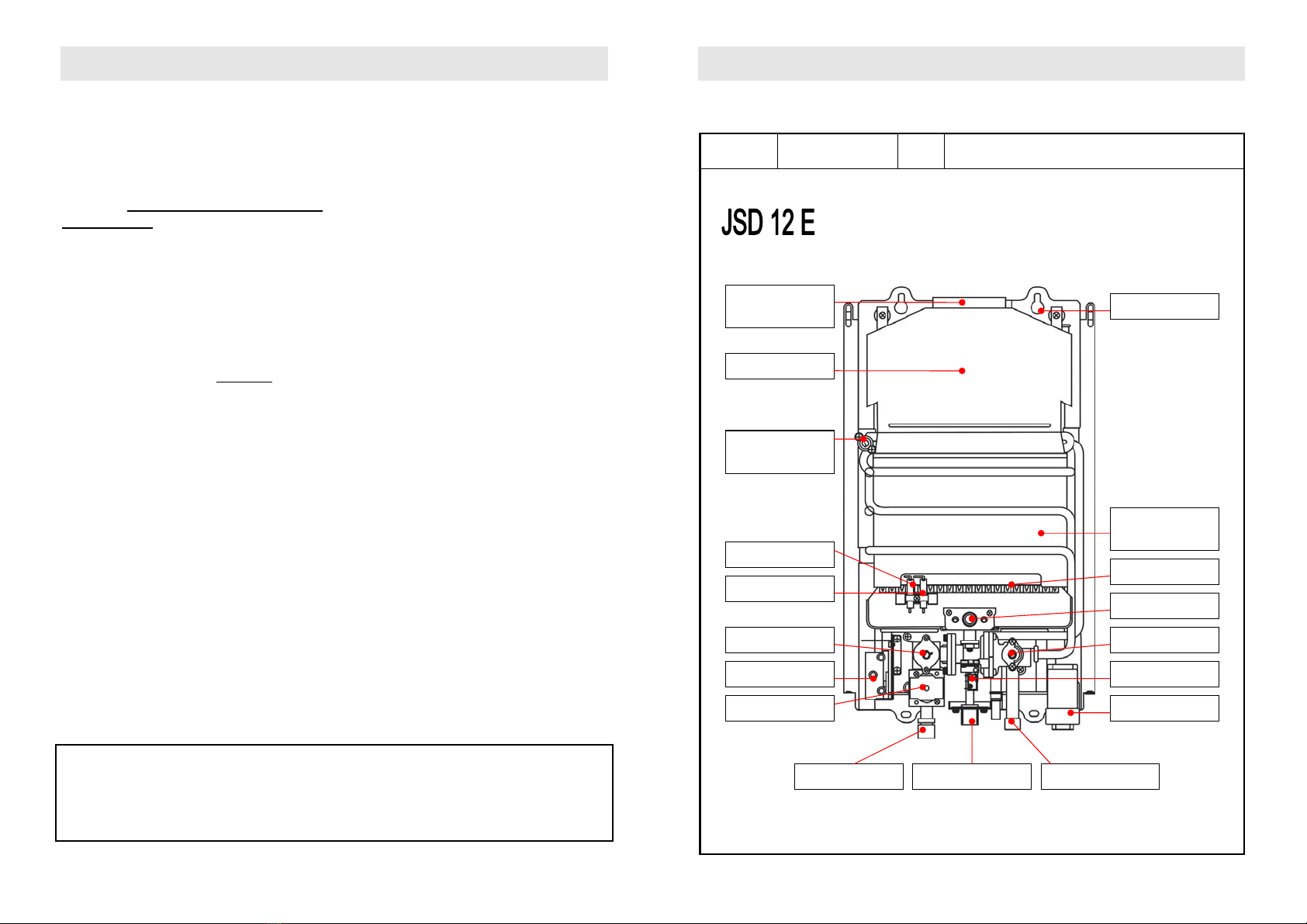
2.1 Performance Layout
Description Household Instant
Gas Water Heater Model JSD 12 E
Front View (Cover Removed)
Flue connector
(Ø110mm )
Flue exhaust
Hang holds
Temp. limit sensor
Ignition sensor
Flame sensor
Ignition control(IC)
Solenoid valve Battery box
Microswitch
Water valve
Gas valve
W/S gas valve
Burner
Heating
exchanger
Gas inlet (G ½”) Water outlet (G ½”) Water inlet (G ½”)
3
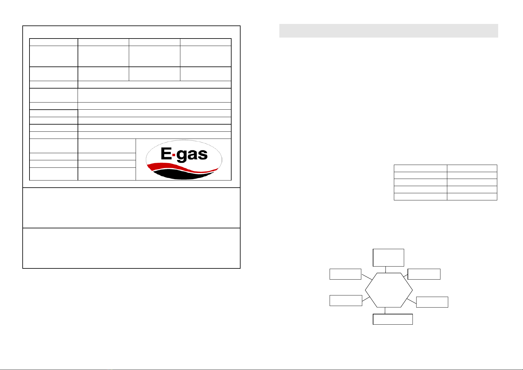
2.2 Main Technical Data & Features
Item Value Item Value
Rated Thermal
Burden (kW) 24
Rated hot water
producing capacity
L/min (Δt = 25 °C)
12
Working Voltage
(V.DC) 3 Power Voltage (V.DC) 3
Distributor: E – Gas Systems
Appliance Model
& Size (mm)
JSD 12 E
819 x 395 x 245
Appliance Type B B 11BS LPG Operating Pressure: 2.8 kPa
Certification Number: I 1810
Type of Gas G20 – 20 mbar G31 – 37 mbar
Jet Size 0.67 mm
Gas Consumption 1.1 kg/hour
Nominal/minimum
Useful Output P = 6.4 kW
Nominal Heat Input Q = 16 kW
Max. Water Pressure 7.5 bar
Min. Water Pressure: 0.25 bar
Features:
This model has accidental flameout safety device, vent pipe anti-block.
Must read the instruction manual before installing and using this appliance and operate it completely according
to the instruction manual.
Warning:
1. Read the technical instructions before installing the appliance.
2. Read the user’s instructions before lighting the appliance.
3. This appliance may only be installed in a room if the room meets the appropriate ventilation requirements.
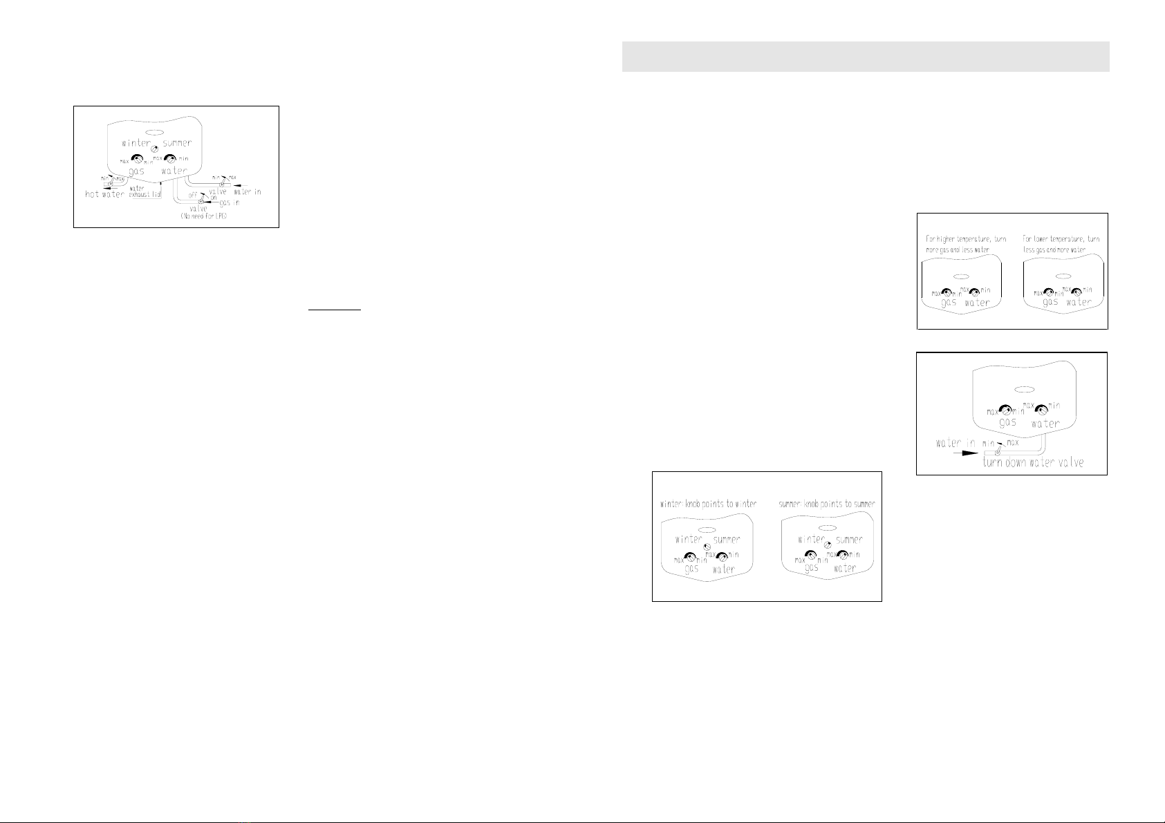
2.3 Description of Control Functions
Winter/Summer Knob: Used to switch from winter mode to summer mode or in a clockwise direction. If it
is in the summer mode, the gas diffusing into the main burner will be cut off and the energy of combustion
will decrease, in this way the gas will be saved in the summer mode.
Water Knob: Used to switch between maximum water flow and minimum water flow.
Gas Knob: Used to switch between maximum gas and minimum gas feed.
4
3. INSTRUCTIONS FOR THE INSTALLER
3.1 Technical Information
3.1.1 The installation, the adjustments and
maintenance listed in this part must only be carried
out by qualified installer. The manufacturer cannot be
held responsible for any damage to persons or things
deriving from an incorrect installation of the appliance.
3.1.2 The safety and automatic adjustment devices
of the appliance may only be modified or exchanged
by the manufacturer or duly authorised supplier.
The flue pipe anti-block device is a thermostat which
is fixed on the left side of flue outlet on the smoke
cover. When the flue pipe is blocked, the temperature
of the flue outlet will rise. After it is risen to a rated
value, the sensor in the thermostat will start to break
the circuit and cause the igniter stop. It must be
understood that the igniter is the main controller in the
machine, so if the circuit is broken, the
electromagnetic valve will stop working automatically,
and the ignition needle will also stop igniting. After
cleaning the flue pipe (we advise you to ask our after
sale service centre to help you), please press the
reset button to restart the sensor in the thermostat,
only in this way, it is safe to restart your gas water
heater.
3.2 Installation
3.2.1 Attention: Water heater should be installed by
a registered gas appliance installer, carrying out the
installation in strict conformity to the manufacturer's
instructions and local bylaws to avoid any danger.
3.2.2 Position of Installation
INSTALL WATER HEATER OUTSIDE OF THE
BATHROOM
The water heater should be installed in an individual
room, separate from the bathroom and family living
room. Keep the room well ventilated so as to avoid
toxicosis by carbon monoxide. The air rate necessary
for discharge of combustion gas is listed as follow:
Heat Input ( kW) Min Gas Output(v/s)
≤12 16 v/s
12~16 20 v/s
16~20 24 v/s
20~26 30 v/s
INSTALL IN A SEPARATE ROOM
NO
INSTALLATION
Stair and
safety exit
Cabinet
Bathroom
Living room
Bedroom
Basement
5
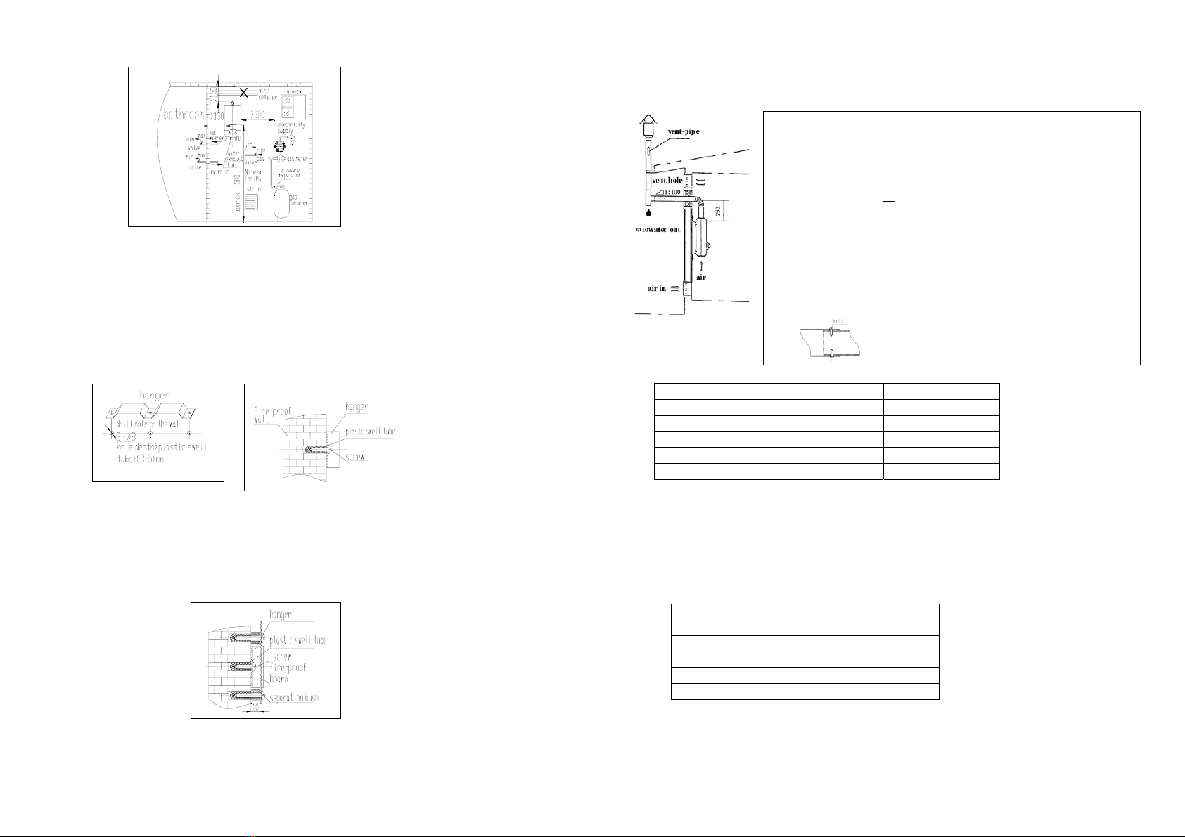
THE CORRECT POSITION IN THE INSTALLATION ROOM
NOTES:
⇒The position of water inlet, water outlet & gas pipe shall be according to the marks on water heater body.
⇒Check carefully after installation; make sure there is no gas or water leakage.
⇒Rubber hose should not be longer than 2 m.
⇒No wire, pipe or hose should go through behind or above water heater body.
3.3 How to install
INSTALLATION OF THE HANGER --- SHOULD BE INSTALLED HORIZONTALLY
The walls sensitive to heat, for example wood, shall be protected by suitable insulation. We advise you to
equip the appliance on the fire-proof wall, in case of non fire-proof wall, please underlay a fire-proof board,
100 mm bigger than the water heater from every side and 10 mm away from the wall. It should not be fixed
directly on the wall which is sensitive to heat, for example wood, shall be protected by suitable insulation,
such that the clearance between the wall on which the appliance is installed and the hot parts on the outside
of the boiler are observed.
6
HANG UP THE WATER HEATER
Hang up the water heater onto the hanger vertically
INSTALLATION OF VENT-PIPE
Diameter of the vent pipe
Model Inner diameter Outer diameter
6L Ø 90 Ø 90+2 mm
7L Ø 90 Ø 90+2 mm
8L, 9L, 10L Ø 110 Ø 110+2 mm
12L Ø 110 Ø 110+2 mm
16L Ø 135 Ø 135+2 mm
An adapter can be used to help users to join the present flue pipe to other flues of different diameter.
HOW TO SET UP VENTILATION PASSAGE
A Air-in hole should be at a well-ventilated position below ½ of the room height.
B The vent hole should be set outside and near the top of the room and far from the vent-pipe in a
ventilation condition.
C Air entry and Vent area
THERMAL
BURDEN (kW)
MIN. AREA OF THE AIR-IN HOLE
AND VENT HOLE (cm2)
≤12 100
12~16 130
16~20 160
20~26 200
The water heater must have the vent-pipe installed. Vent-pipe installation should be as
follows:
The height of the vent-pipe should be so as to ensure the complete exhaust of the smoke to
the outside.
B The horizontal part of the vent-pipe should be less than 3 m, and the vent should be
inclined down a little so that the condensate water or rains does not flow backwards.
C Elbow of the vent-pipe should be 90° and should not consist of more than 3 pcs.
D The outer part of the vent-pipe should be at least 250 mm above the start of the roof.
E Top of the vent-pipe should be fitted with a wind cap to prevent the ingress wind, rain and
snow. The location of the wind cap should not be in the Æolian zone. The distance should
not be less than 600 mm against the building around and its hatch.
F The vent pipe should be installed in clear air, and not in the path of other air passages.
G Make sure there are no air leakage at the joints by fixing it tightly with bolts.
7
Installation of VALVE:
Valves should be installed in respect of the gas-in pipe and water-in pipe prior to their connection to the water
heater. The hot water pipe should have a valve as well. After installation, testing should be carried out to
ensure there are no gas and water leakage.
3.4 The performance of vent pipe anti-block
device
Warning: the vent pipe anti-block device shall not be
put out of operation.
3.4.1 When installing the flue pipe anti-blocking
device, the connecting end of the device must be
connected with the igniter.
3.4.2 It may result in the leakage of combustion gas
to be threatened to people’s life when there is
untimely interference with the flue pipe anti-block
device.
3.4.3 When the flue pipe anti-blocking device cannot
work properly and needs replacing, it is
recommended to use the same device of the same
model provided by the manufacturer. Check whether
the device can work normally after replacing by
restarting the gas water heater.
3.4.4 In case of repeated shutdown of the appliance,
it will be necessary to contact our customer’s service
desk to take appropriate action to remedy the
discharge fault.
3.5 Repair and Maintenance
3.5.1 Water heater shall be checked by
professional personnel every 6~12 months.
Check List:
1. Sealing of fuel gas route system; sealing of water
route system;
2. Clean filtration sieve on water inlet orifice to avoid
blockage;
3. Functions of all operating parts;
4. Flame of combustion;
5. Carbon accumulation of heat exchanger;
6. Proper air ventilation in room where water heater
is installed.
7. Gas decompressor
3.5.2 Items checked and maintained by
professional personnel:
1. The flexibility of water and gas linkage;
2. Clean carbon accumulation on buckling piece of
heat exchanger;
3. Grease gas valve and its core;
4. Carbon accumulation and oxidation coating on
ignition and induction needles;
8
4. INSTRUCTIONS FOR THE USER
4.1 Operation
4.1.1 START UP
Presentation
1. Insert two off # 1 size batteries in the battery box.
2. Open the valves of gas-in and water-in.
3. Inspect the gas source if there is leakage.
4. Inspect if there is any leakage on the hot water outlet and water inlet.
5. Turn on the hot water-out valve
4.1.2 IGNITION
When water pressure is above 0.5 bar, the ignition is
automatically initiated when you open the hot water valve.
For the newly installed water heater, the gas pipe might be
filled with air and cannot be ignited for the first time. Please
repeat on & off to exhaust the air until water heater is finally
ignited.
4.1.3 TEMPERATURE CONTROL
To adjust the water and gas until it’s comfortable.
When you use the water heater for first time, cold water
should not be turned up too much. Avoid a too low pressure
which can effect normal system operation. In some areas,
the water pressure may be too strong and thus water
cannot be heated. In this case, please turn down the
water-in valve.
The Winter/Summer option has an adjustment to winter or
summer mode (Operation of temperature control).
4.1.4 SHUT-OFF
1. To stop using the water heater, please shut off the gas valve or water-in valve;
2. Please drain water from the system if the temperature is below 0 °C or if the appliance is out of use and
dormant for an extended period of time.
4.1.5 RESTART
1. If the water heater stops during operation, close the hot water-out valve or water-in valve;
2. Open the closed hot water-out valve or water-in valve again;
3. Don’t touch the water from the water heater after restarting in order to avoid the scalding.
4.2 NOTES ON SAFETY
THIS APPLIANCE IS ADJUSTED TO OPERATE ON LPG ONLY.
9
4.2.1 IF YOU SMELL GAS:
•Turn off the gas supply at the bottle
•Extinguish all naked flames
•Do not operate any electrical appliances
•Ventilate the area
•Check for leaks as detailed in section 5.2.1 If odour persists, contact your dealer or gas supplier
immediately
4.2.2 Burn-Back (Fire in Burner or Chamber)
In the event of a burn-back, where the flame burns back to the jet, immediately turn off the gas supply at
the control valve. After ensuring the flame is extinguished, re-light the appliance in the normal manner.
Should the appliance again burn back, close the control valve and call a service technician. Do not use the
appliance again until the technician has declared that it is safe to do so.
4.2.3 Important Information for the User
This appliance may only be installed by a registered LP Gas installer. It is illegal to have it installed by a
non-registered LP Gas installer. Upon completion of the installation, the installer is required to explain the
safe operation details of the appliance together with safety instructions. You will be asked to sign
acceptance of the installation and be provided with a completion certificate.
4.2.4 Important Information for the Installer
This appliance may only be installed by a LP Gas installer registered with the Liquefied Petroleum Gas
Association of South Africa. This appliance must be installed in accordance with the requirements of SANS
10087-1 and any fire department regulations and/or local bylaws applicable to the area. Upon completion
of the installation you are required to fully explain and demonstrate to the user the operational details and
safety practices applicable to the appliance and the installation.
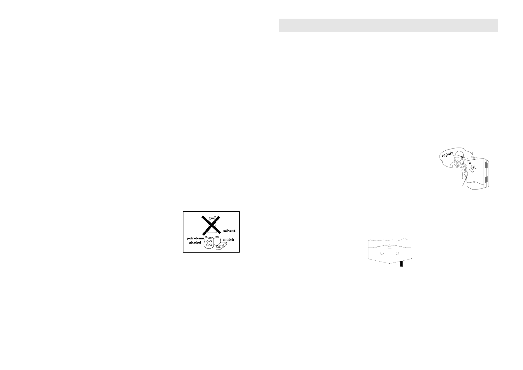
No inflammable, explosive and corrosive substances could be placed around water heater, the minimum
or appropriate distances between them are according to the store instruction accompanying the
inflammable or explosive materials. The gas water heater can be regarded as a fire source.
4.2.5 Forbid any interference with a sealed component.
4.2.6 If the evacuation of the combustion products is disturbed, the flue pipe
anti-blocking should interrupt the admission of gas to the burner. Please
turn off the water inlet and press the reset button of the thermostat, then
turn them on again. If there are repeated interruptions, please call
specialist for help.
4.2.7 Avoid scald: To resume using the water heater after a break; do not
touch the hot water immediately. And during the use or just right after
finish, except the knobs, do not touch the outer shell to avoid scald.
4.2.8 DO NOT USE WATER HEATER FOR OTHER PURPOSES EXCEPT FOR PRODUCING HOT WATER.
The water heater is used for intermittently producing hot water. It should not be used for supplying drinking
water or drying clothes.
10
5. INSTRUCTIONS FOR THE USER: CLEANING AND MAINTENANCE
5.1 Cleaning
5.1.1 Get rid of accumulated dirt and dust on the casing of the water heater using a cloth. Do not use chemical
or volatile cleaning agents that may change casing’s colour.
5.1.2 Clean accumulated dusts and carbon inside vent-pipe and heat exchanger periodically to ensure the
smooth passage of smoke.
Note: Remove the vent-pipe, clean the inside with a brush. Do not drop dirt and dust into fire hole of the burner
or parts of the electric appliance and do not loosen or damage any other parts as well. To re-fix the vent-pipe
after cleaning, take care to tighten the sealing joints.
5.2 Maintenance
5.2.1 Check Gas Leakage
Check regularly with soapy water smeared around the gas pipe joints, to make sure there’s no gas
leakage.
Stop using the water heater and check carefully when abnormal situations occur during normal using.
In case of gas leakage, please cut gas supply immediately, open doors and windows to ventilate the
bathroom with natural air. Water heater can only be used after the gas
completely dissipates. In order to avoid accidents, all fire sources and
electric switches should be shut off.
Do not use the water heater during its MALFUNCTION, and do not
disassemble it personally. When trouble occurs during use, please
contact our Assistance Centre for advice. Water heater should be
maintained by professionals regularly (liquid petroleum gas type,
every 2-3 years).
5.2.2 How to protect against frost
It is necessary to empty the water tank when air temperature is below 0 °C, or if the unit is not used for a
long time, the steps to follow:
Loosen the screw in the water drainage valve. The water remaining in the water tank will flow out until the
water tank is empty.
Water Drainage Valve
11
6. WHAT TO DO IF…
6.1 Some problems can be caused by simple settings. This can easily be resolved without
having to call technical assistance.
If your appliance is not working efficiently:
•Make sure the gas cock is open
•Check that the knobs are set correctly and then repeat the operations given in the handbook
NOTE: WATER HEATER SHOULD NOT BE USED CONTINUOUSLY FOR A LONG TIME.
6.2 The following situations are not real problems. You can handle these problems by
yourself by following the following steps. If the water heater still does not work in a good
condition, we advise you to call the gas specialist for help.
PROTECTIVE FUNCTION REACTION REMARKS
Water pressure too high If water pressure is over 7.5 bar, the
water-out valve will release water
and lower the pressure
Increase the valve pressure limit
according to local water supply
pressure
Water pressure too low If water pressure is below 0.25 bar,
the water heater cannot be ignited
Use the water heater later when
pressure becomes higher
Low battery The power of battery will become
less after use for some time, thus
the water heater cannot be ignited.
Change battery
12
7. TROUBLESHOOTING
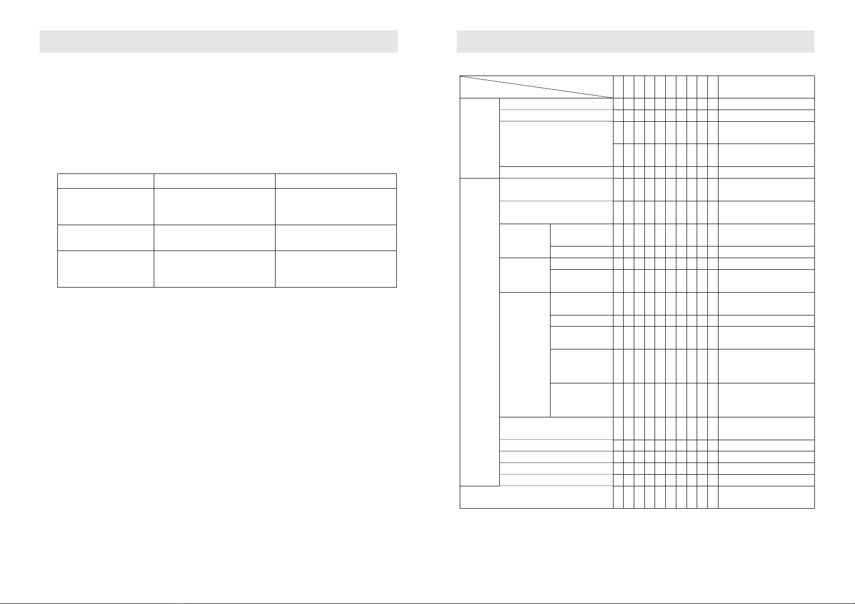
7.1 Maintenance and Repair Guide to Common Malfunctions
A B C D E F G H I J Solutions
Improper
Operation
Overall fuel gas valve is unopened ●Open overall valve of gas supply
Water supply valve is unopened ●Open valve of water supply
Improper regulation method of water
temperature
●
Enlarge gas volume, reduce water
volume
●Reduce gas volume, enlarge water
supply
Improper position of water switch ●Turn water knob to hot water point
Surroundings
Air exiting inside fuel gas pipe ●●
Repeat opening and closing hot
water valve for several times
Inadequate fresh air supply ●
Improve ventilation and ensure air
supply
Fuel gas pressure Too high ●●●●Regulate pressure relief valve,
reduce overall gas supply
Too low ●●●Check if gas rubber pipe twists or not
Water pressure
Too high ●Reduce water supply
Too low ●●●●●Utilize when water pressure recovers
to normal
Inadequate
supply of fuel gas
Gas valve is half
opened ●Open gas valve completely
Too long pipe ●Shorten rubber pipe
Too small through
diameter of joints ●Displace joints of rubber pipe
Improper choice of
specification of
pressure relief valve
●
Water heater with a content of over 8
litres shall adopt a pressure relief
valve (LPG) of 1.2 m3/h
Simultaneous
consumption of fuel
gas by several users
●Stop other users' using fuel gas
Blockage of water route ●●Clean filtration net on water admitting
orifice
Blockage of shower ●●Clean shower device
Blockage of vent pipe ●●●Clean flue pipe
Inadequate battery voltage ●●●Displace batteries
Too low water temperature ●Reduce water volume
Other causes ●Ask for professional personnel to
repair it
A. Ignition failure
B. Blasting combustion
C. Flameout during operation
D. Too low temperature
E. Too high temperature
F. Sparks from fire peep hole
G. Removed flame and renegade fire
H. Returned fire
I. Flameout at point of large water volume
J. Other malfunctions
Malfunction
Causes

13
TECHNICAL ASSISTANCE AND SPARE PARTS
Before this appliance left the factory it was tested and set by specialized, expert personnel to guarantee the best
functioning results.
Qualified personnel must do any subsequent repairs or adjustments that may be necessary with the maximum
care and attention.
For this reason we always recommend contacting the nearest Assistance Centre of ours, specifying the brand,
model, serial number and type of problem you are having with it. You will find the relative data printed on a label
affixed behind the appliance and on the label affixed on the cover of this handbook.
With this information the technical assistant can come with the right spares and guarantee a prompt attention.
You will find original parts and optional accessories at our Technical Assistance Centres and authorised dealers.
8. CONTACT DETAILS
E-GAS LPGSASA
AECI Site Western Cape: 021 939 9441
Somerset West, 7130 Free State: 051 522 4363
Western Cape Gauteng: 011 886 9702
South Africa KwaZulu Natal: 031 563 3535
Tel: 021 851 2436

The appliance was designed and manufactured in accordance to International Standards and is
certified as a safe appliance by the Liquid Petroleum Gas Safety Association of South Africa
Table of contents
Popular Water Heater manuals by other brands


Chaffoteaux & Maury
Chaffoteaux & Maury 1F G.C. 51 980 39 Installation and servicing instrucnions

HTP
HTP Everlast EVC080 use and care manual

giggas
giggas Giw-218S Operation manual

Kenmore
Kenmore 33968 - Power Miser 9 specification

fothermo
fothermo CPVB-10 manual

Wijas
Wijas PERFECT MIX Series Installation and operating instructions

Ariston
Ariston 50 Series Instructions for installation, use, maintenance

Kenmore
Kenmore POWER MISER 153.33066 owner's manual

Rinnai
Rinnai RES-ED440H-W instruction manual

Hatco
Hatco POWERMITE PMG-60 Specification sheet

CHAFFOTEAUX
CHAFFOTEAUX FLUENDO PLUS ONT C 11 EU user manual

VESTEL
VESTEL TRV 50 Service manual