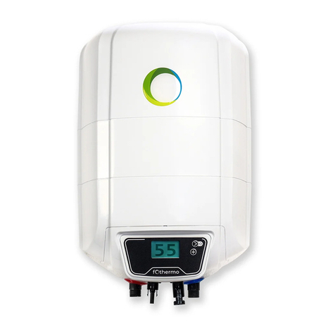
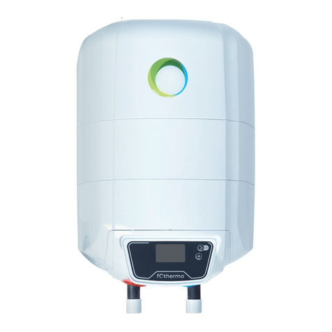
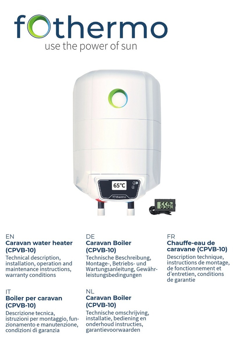
fothermo CPVB-10 User manual

EN
Caravan water heater
(CPVB-10)
TECHNICAL DESCRIPTION
INSTALLATION, OPERATION AND MAINTENANCE
INSTRUCTIONS
WARRANTY CONDITIONS
DE
Caravan Boiler
(CPVB-10)
TECHNISCHE BESCHREIBUNG
MONTAGE-, BETRIEBS- UND
WARTUNGSANLEITUNG
GEWÄHRLEISTUNGSBEDINGUNGEN

Table of Contents | Inhaltsverzeichnis
EN
Specifications 3
Option pages at a glance 4
Select operating mode 4
Assembly 5
Connection 6
Drainage 7
Further information 8
General warnings..................................................................................................................................................................................................... 8
Safety instructions................................................................................................................................................................................................... 8
Further important notes ......................................................................................................................................................................................... 8
Technical data.......................................................................................................................................................................................................... 9
Assembly................................................................................................................................................................................................................... 9
Connection to the water supply............................................................................................................................................................................. 9
Electrical connection............................................................................................................................................................................................. 11
Connection of an external AC Reheating: ........................................................................................................................................................... 12
Operation................................................................................................................................................................................................................ 12
Maintenace ............................................................................................................................................................................................................. 13
Malfunction ............................................................................................................................................................................................................ 14
Enviromental protection....................................................................................................................................................................................... 14
Warranty ................................................................................................................................................................................................................. 14
Spezifikationen 15
Menü-Seiten im Überblick 16
Betriebsmodus auswählen 16
Montage 17
Anschluss 18
Entleerung 19
Weiterführende Informationen 20
Allgemeine Warnhinweise .................................................................................................................................................................................... 20
Sicherheitshinweise .............................................................................................................................................................................................. 20
Weitere wichtige Hinweise.................................................................................................................................................................................... 20
Technische Daten .................................................................................................................................................................................................. 21
Montage .................................................................................................................................................................................................................. 21
Anschluss an die Wasserleitung ........................................................................................................................................................................... 21
Elektrischer Anschluss .......................................................................................................................................................................................... 23
Anschluss einer externen AC-Nachheizung: ....................................................................................................................................................... 24
Betrieb..................................................................................................................................................................................................................... 24
Wartung und Instandhaltung ............................................................................................................................................................................... 26
Störungen............................................................................................................................................................................................................... 26
Umweltschutz ........................................................................................................................................................................................................ 26
Gewährleistungen.................................................................................................................................................................................................. 27
Contact | Kontakt 28
IMPORTANT!
Please read these operating instructions carefully before
installing and commissioning the hot water tank!
WICHTIG!
Bitte lesen Sie diese Bedienungsanleitung vor Montage und
Inbetriebnahme des Warmwasserspeichers sorgfältig durch!

EN
www.fothermo.com 3
Specifications
UNIT
10 LITER
PHOTOVOLTAIC WATER HEATER
Product model
-
CPVB-10
Volume
l
9,5
Rated pressures
MPa
0,7
IP-class
-
X1
Gross weight (± 3%)
Kg
8
Dimensions (length, width, height)
cm
44x33x30
Check and pressure relief valve
-
✓
Cathode protection
-
✓
Emailed protection
-
✓
Insulation
-
✓
Energy efficiency class
C
Water connection
-
G½ (M)
Integrated reverse polarity protection
-
✓
Digital display
-
✓
CE - certified
-
✓
PHOTOVOLTAIC INPUT
Max. photovoltaic heating power
W
550
Max. photovoltaic current consumption
A
15,5
Max. water temperature
°C
65
Integrated MPP tracker
-
✓
Recommended photovoltaic power
Wp
100 - 300
Max. connected photovoltaic power
Wp
1.500
Max. open circuit voltage
Voc
42,4
Photovoltaic connector
-
MC4
REHEATING VIA 230 V POWER GRID
Type of reheating
Power supply unit
(12V, 18V or 24V)
Heating power
W
60 (12V), 160(18V) or
240(24V)
Adjustable water temperature range
°C
5 - 65
HEATING VIA RECHARGEABLE BATTERY
Recommended technology
LFP, lead acid
Voltage level
V
12 or 24
WATER HEATING DEPENDING ON THE CURRENTLY AVAILABLE
PHOTOVOLTAIC POWER
200 W
°C/h
18
400 W
°C/h
36
550 W
°C/h
50

EN
4 www.fothermo.com
Option pages at a glance
Nr
Information/Input option
1
Shows the water temperature in °C.
2
POWER IN: Shows the instantaneous power consumption of the boiler.
VOLTAGE: Shows the current supply voltage of the boiler.
3
USED PV ENERGY: Displays the total PV energy consumed by the boiler.
4
CHANGE SYSTEM MODE: You can use the - button to change the operating mode.
IMPORTANT! Depending on which operating mode is active, option page nr. 5 differs.
5
(System Mode 1:
Photovoltaic)
Reheat Temp: With the - button you can change the photovoltaic reheat
temperature via the power supply unit.
5
(System Mode 2:
PV Battery)
Battery DCH Volt: With the - button you can change the final discharge voltage of
your battery. The system does not allow the voltage to fall below this value.
WARNING! Do not undercut the end of discharge voltage of the battery, otherwise the
battery could be damaged.
6
Change Maximum Temperature: With the - button you can change the maximum
temperature.
7
Shows the boiler type and the version number of the software.
8
Shows the hardware version number.
Select operating mode
mode
description
primary
energy source
secondary
energy source
1: PV Home
The boiler is primarily powered by photovoltaic
current. This mode
should be selected if a PV module is connected
or if there is an external energy management
system (e.g. solar charge controller with deep
discharge protection) that releases the current
for the boiler.
PV module
(Via MC4 Input)
Power supply
(Via 4 pin external
connector)
2: PV -
Battery
Via the MC4 contact plugs, a battery can also be
connected. As soon as the connected battery
reaches a voltage of 13.5 V, the excess energy is
used to power the boiler. This happens while the
battery is being charged.
PV module
(Via MC4 Input)
12 V or 24 V battery
Approved:
LiFePO4, lead acid
battery
(Via 4 pin external
connector)

EN
www.fothermo.com 5
Assembly
The caravan boiler must be mounted on a solid base plate with four
screws. Use suitable screws or other mounting systems for your base
plate.
IMPORTANT! The Installation of the photovoltaic boiler is only horizontally possible.
1.
2.
3.
4.

EN
6 www.fothermo.com
Connection
1Water heater
2Water inlet
3Water outlet
4shut off valve*
5combined check and -
pressure relief valve
6 Pressure reducing
valve*
7Cold water
8Hot water
9Device plug for
external mains current
10 Power cable*
*not included
Heating time of the water depending on PV-Power
Power
Value
CPVB-10
200 W
°C/h
6
400 W
°C/h
12
550 W
°C/h
16
Note
The values given in the table are intended as a
guideline. The heating times depend on many factors
(power, ambient air temperature, water withdrawal)
and may differ from reality. The greater the connected
photovoltaic power,
the more the water can be heated on days with low
solar radiation. The water is heated with a maximum
power of 550 W, even if more photovoltaic power is
available.
9
10
*necessary if water pressure

EN
www.fothermo.com 7
Drainage
The water in the boiler must not freeze. Frozen water
in the boiler can cause damage or a defect of the
appliance. If necessary, the contents of the boiler can
be drained via the non-return/overpressure valve.
Proceed as follows:
• Ensure that any water that leaks from the non-
return/overpressure valve can drain away safely. This
is important to prevent possible water damage.
•Disconnect the water heater from any live electrical
wiring.
• Shut off the cold-water supply.
• Open the hot water tap of the mixing tap or
disconnect the hot water pipe (return pipe) of the
water heater
• Tilt the small lever of the check/relief valve 90 °.
• The water should now drain away. The Drainage is
complete when no more water comes out of the
valves.
• Small amounts of water remain in the boiler even
after emptying. This is fine and does not cause any
damage
WARNING! The draining water can be hot - risk of scalding!
These steps do not ensure complete emptying of the water tank.
Current source
WARNING! When connecting several photovoltaic modules,
these must only be connected in parallel.
Usable energy sources
Source
Voltage
Type
PV module
0-42,4 Voc
-
Battery
12 V, 24 V
Lead acid, LiFePO4
External energy management
12-42,4 V
-
WARNING! Connect the power supply only when the water heater is filled.

EN
8 www.fothermo.com
Further information
Dear clients, thank you for choosing device from fothermo system AG.- Germany!
Itwill be a trustworthy helper in your household for many years because in its production we have
combined high quality materials and innovative technologies. To be sure of its hopeful and trouble-
free operation, please read the installation and operating instructions carefully.
WARNING! Before installation and operation with the appliance, read carefully the present manual!
General warnings
Be sure to carefully read the instructions and
warnings in this manual before installing and
operating the water heater. The information
contained in this manual is intended to familiarize you
with the water heater, the rules of its correct and safe
operation, and the minimum requirements for its
maintenance and servicing. Furthermore, you are
obliged to make this manual available to the qualified
persons who will install and potentially repair the
appliance. The installation of the water heater and the
verification of its functionality is not within the
distributor's warranty obligation nor the manu-
facturer.
These instructions should always be kept near the
appliance for future reference. Compliance with the
rules here described is part of the measures for the
safe use of the product and is considered part of the
warranty conditions.
Safety instructions
WARNING! There is a risk of burns or scalding when
using the appliance!
WARNING! This appliance may be used by children of
age over 3 years old and persons with reduced
physical, sensory or mental capabilities, or lack of
experience and knowledge, where they are under
supervision or instructed about the safe use of the
appliance and understand the dangers. Children must
not be allowed to play with the unit! It is absolutely
forbidden that children undertake cleaning or
servicing of this appliance! Children aged from 3 to 8
years are only allowed to operate the tap connected
to the water heater.
IMPORTANT! Only qualified persons may install the
water heater and connect it to the water pipe
following the specifications given in this manual and
the relevant local regulations. The protective devices
provided or recommended by the manufacturer, as
well as all other assemblies, are UNCONDITIONALLY
to be installed!
IMPORTANT! Be sure to fill the water heater with
water before connecting it to the electrical supply!
Failure to comply with the electrical connection
conditions affects the safety of the appliance,
whereby the water heater must not be operated.
IMPORTANT! Observe the maximum permissible
pressure (see chapter: Technical data).
Further important notes
•The appliance is under pressure. During
heating, expansion water may drip from
the pressure relief valve.
•Operate the pressure relief valve
regularly to prevent it from being stuck,
e.g. due to limescale deposits.
•Install a type-tested pressure relief valve
in the cold-water supply line. Note that
depending on the pressure of the supply,
you may also need a pressure reducing
valve.
•Mount the pressure relief valve with the
opening facing down.
•Mount the pressure relief valve and the
drainpipe with a steady downward slope
in a frost-free room.
•Dimension the drainpipe to allow the
water to flow off unhindered when the
pressure relief valve is fully open.
•The pressure relief valve opening must
remain open to the atmosphere.

EN
www.fothermo.com 9
•This device contains a support battery,
which is not replaceable. It is necessary
for the display to function at night. A
defect does not limit the basic
functionality.
•This unit may be operated up to an
altitude of 4000 m above sea level.
•Reheat Function is optional. You can
either only use PV-energy or PV-energy
combined with reheat-power.
Technical data
This water heater can provide hot water from the
mains water supply or other pressure-operated water
supply for several consumers. The water used for
heating must comply with the requirements in the
normative documents for service water, in particular:
Chloride content up to 250 mg/l; electrical
conductivity more than 100 µS/cm, pH value 6,5-8 for
enamelled hot water tanks. The thermal insulation
consists of CFC-free polyurethane foam.
The maximum electrical power with PV-energy of the
water heater is 550 W. The actual power consumption
of the heating element depends on the connected
photovoltaic power as well as on the radiation
strength provided by the sun. The water is heated to a
maximum of 65 °C to ensure scalding protection.
Detailed information can be found in the data sheet or
on the nameplate.
The water heater is equipped with a combined check
and pressure relief valve (Table 1, No. 5) to prevent
overpressure during appliance operation. The water
tank is made of steel with a high-strength enamel
coating and additional cathode protection provided
by a magnesium anode.
Assembly
Always install the water heater lying down, in a dry
environment. The device is intended for fixed floor
assembly. Make sure that the assembly surface is
sufficiently stable to withstand forces that act on the
boiler or its mounting system when driving.
When choosing a suitable substrate for the hot water
storage tank, the following must be taken into
account:
• Type and material
• Dimensions of the device,
• Type of fastening
• Location of fasteners for floor mounting
• Arrangement of water and electricity lines
• Degree of protection against water splashes
The installation site must comply with the
requirements of the water and electrical installation.
Sufficient space for the water connections must be
provided during installation.
The boiler is bolted to the floor using the attached
mounting rails. Four screws are used for this. The
type, length and diameter of the screws must be
selected according to the nature of the floor. Only
with the right screws it is possible to safely install the
boiler.
Connection to the water
supply
When connecting the device to the water supply,
please observe the indicated arrows and rings around
the cold and hot water pipes (supply and return
pipes). The cold-water pipe features a blue ring and is
marked with an arrow pointing towards the pipe. The
hot water pipe is indicated by an arrow pointing out of
the pipe and a red ring.
The water heater is equipped with a combined check
and pressure relief valve, which is included in the
product packaging and MUST be installed on the cold-
water pipe. The arrow on the body of the valve, which
indicates the direction of water flow through the
valve, must be followed during this installation.
WARNING! The absence or improper installation of
the combined valve supplied with the product is
grounds for voiding the product warranty.
WARNING! It is FORBIDDEN to install any kind of shut-
off fittings between the combined valve and the water
heater! It is absolutely forbidden to obstruct the
lateral opening of the combined valve and/or to block
its lever!
The pipe connectors have male G½ threads.

EN
10 www.fothermo.com
The water heater operates by the pressure of the
water pipe. The water pressure of the water supply
system should be higher than 0.1 МРа (1 bar) and
lower than 0.5 МРа (5 bar). If the pressure of the water
pipe exceeds 0.5 MPa, a pressure reducing valve must
be installed.
If additional equipment, which is not included in the
standard delivery, must be used to comply with local
regulations, they must be installed according to these
specifications.
In case the water pipes are made of copper or other
metal which differs from the metal of the water tank,
as well as if connecting elements made of brass are
used, non-metal fittings must be installed on the
supply and return side of the water heater (dielectric
fittings).
WARNING! The installation of any shut-off or non-
return fittings between the pressure relief valve and
the water heater, as well as blocking the side opening
of the pressure relief valve and/or locking its lever is
prohibited!
A drainage system to remove any water that may drip
from the side opening of the pressure relief valve is
recommended. The drain line must be designed with
a constant downward slope in a frost-free
environment and must remain open.
After connecting the water heater to the water supply,
fill the tank with water. The sequence of steps to be
performed is:
•Fully open the hot water tap at the
furthest point of use.
•Open the shut-off valve. (Table 1, No. 4)
•Wait until the air is released from the
system and a strong jet of water flows
from the mixer tap. Let the water run for
about 30 seconds.
•Close the hot water tap at the extraction
point.
•Lift the small lever of the pressure relief
valve (Table 1, No. 5), wait 30-60 seconds
until a strong stream of water flows out of
the side opening of the valve.
•Loosen the valve lever.
WARNING! If no water or only a thin stream of water
flows out of the valve opening, this indicates a
malfunction. A possible contamination of the water
pipe might be present. The fault must be eliminated
before the unit is put into operation.
It is FORBIDDEN to proceed with appliance electric
connection before eliminating the reason for
malfunction!
WARNING! Failure to comply with the requirements
for connection to the water supply system may cause
partial filling up of the water tank and malfunction of
the heating element, or when the combined valve is
not installed at all or has been improperly installed.
This may even cause destruction of the water tank,
the room and/or other damages to tangible and
intangible property. Such consequences are not
within the scope of manufacturer or seller warranty
liabilities and shall be at the expense of the party,
which has not observed the present manual
instructions.
WARNING! The combined check and pressure relief
valve is one of the protective devices that ensure the
safe operation of the water heater. The use of the
water heater with a damaged or
removed/unassembled combined check and pressure
relief valve (safety valve) is STRICTLY PROHIBITED!
The pressure relief valve can also be used to drain the
water from the tank if desired. In such case, proceed
as follows:
•Disconnect the water heater from any live
electrical wiring.
•Disconnect the cold-water inlet.
•Open the hot water tap of the mixing tap
or disconnect the hot water pipe (return
pipe) of the water heater.
•Lift the small lever of the pressure relief
valve (Table 1, No. 5) and wait until no
more water leaves the valve.
•WARNING! The running water can be hot
–risk of scalding.
These steps do not still secure the complete draining
of the water out of the tank. It is completed only by a
qualified person because it requires complete
disconnection of the appliance electric circuit and
dismantling the water tank flange.
WARNING! It is STRICTLY PROHIBITED to turn on the
heater power while the water tank is partially or
completely emptied of water! Do not forget to fill the
tank with water before putting it back into operation.
WARNING! The coolant circulation through the heat
exchanger of a water heater equipped with such
device is PROHIBITED when the water tank is partially
or completely emptied of water.

EN
www.fothermo.com 11
WARNING! When draining the water out of the water
tank all necessary precautions must be taken to
prevent damages from flowing out water.
IMPORTANT! In Denmark, Sweden, Norway and
Finland, the connection of the water heater to the
public water supply may only be performed using a
suitable pressure reducing valve. The local
regulations must be observed.
Electrical connection
WARNING! Any electrical connection may only be
performed when the water heater is filled with water.
IMPORTANT! The water heater is powered by direct
current. The water heater is protected against electric
shock "class III" and may only be supplied with safety
extra-low voltage (SELV). Only power sources
recommended by the manufacturer may be
connected. A faulty and/or unsuitable power supply
involves a high risk and is likely to cause an accident.
The connection cables of the device must be replaced
if they are damaged.
IMPORTANT! Photovoltaic modules may ONLY be
connected in parallel. When connecting more than
one photovoltaic module, always use a suitable
connector for parallel connection. For more
information, refer to the illustration "Parallel PV-
Connector". Connecting photovoltaic modules in
series will damage the water heater.
Parallel PV-Connector
Pay attention to correct polar-
ity when connecting!
Connection of PV-modules in parallel configuration only!
Serial connection will damage the unit!
The electrical connection of the water heaters is
performed using MC4 plugs. Check the functionality
of the appliance after the electrical connection has
been performed. When all supply connections are
removed, the water heater is completely
disconnected from the power sources.
CONNECTION OF PV-MODULES:
IMPORTANT! The installation and electrical parallel
connection of PV modules may only be carried out by
a qualified person and may not endanger third
parties. When installing the photovoltaic modules, the
locally prevailing rules and laws must be complied
with.
IMPORTANT! Keep cables out of the way to avoid
tripping over them or getting caught. There is a risk of
injury. The cables must be fastened in such a way that
no tensile load is applied to the connectors.
Furthermore, it must be ruled out that the cables and
connectors rub against surfaces and edges (e.g. in
wind). The cables must not lie in water permanently.
IMPORTANT! Only photovoltaic modules with a
maximum of 60 resp. 120 cells and an open-circuit
voltage of 42.4 V may be connected.
•Photovoltaic modules must be
connected correctly using the factory
supplied MC4 plugs.
•You may connect up to five modules in
parallel. Depending on the module, this
corresponds to an MPP output of
approximately 1500 Wp.
Dimensioning of the required photovoltaic power:
•The higher the number of hours of
sunshine per day, the smaller the
required PV power.
•The warmer the water taken from the
pipeline, the lower the required PV
power.
•Dimension the required photovoltaic
power according to the months with the
lowest solar radiation in which the
photovoltaic water heater will be in
operation.
•The greater the amount of hot water
consumed per day, the larger the PV
power required.

EN
12 www.fothermo.com
The following table serves as a guideline for dimen-
sioning the photovoltaic power needed depending on
the climatic conditions:
Climatic conditions
CPVB-10
Countries with low sunshine
e.g. Northern and Central Europe
300 Wp
Sunny countries
e.g. Southern Europe and Africa
150 Wp
These values given are guidelines. Depending on the conditions
prevailing on site and the specific conditions of consumption, the
appropriate design of the photovoltaic output may vary from the
values described.
Extension of the photovoltaic line:
When extending the photovoltaic cable, the MC4
contact plugs must be properly attached to ensure
functionality and safety. Basically, the PV cable
should be kept as short as possible.
A length recommendation depending on the
connected nominal PV generator power can be found
in the following table.
Connected PV-Power
4 mm²
6 mm²
~325 Wp
≤ 18 m
≤ 27 m
~650 Wp
≤ 11 m
≤ 16 m
~975 Wp
≤ 9 m
≤ 13 m
Recommended cable length (there and back) for different
nominal powers and cross-sections
Connection of an external AC
Reheating:
IMPORTANT! Only use certified connection plugs
(IEC-320 - C13 plugs) recommended by the
manufacturer. Non-compliance will invalidate the
warranty and may damage the water heater. The
external reheating feature extended use of the
photovoltaic boilers. For example, long periods of
bad weather can be bridged by connected AC power.
Operation
WARNING! This appliance may be used by children of
age over 3 years old and persons with reduced
physical, sensory or mental capabilities, or lack of
experience and knowledge, where they are under
supervision or instructed about the safe use of the
appliance and understand the dangers. Children must
not be allowed to play with the unit! It is absolutely
forbidden that children undertake cleaning or
servicing of this appliance! Children aged from 3 to 8
years are only allowed to operate the tap connected
to the water heater.
Operation:
Switch On:
Press the - button for three seconds.
Display:
The present water temperature is shown on the
display.
•POWER IN: Input power of the PV
modules
•VOLTAGE: Input voltage of the PV
modules
•USED PV ENERGY: Total PV energy
utilised
Menu Navigation:
Press the - button briefly. By pressing the button
again, you jump to the next page in the menu.
Settings:
Press the - button repeatedly. This allows
individual adjustments on the unit to be made. Please
note: The adjustments are only active when an
external energy supply is connected to the
photovoltaic water heater.
•CHANGE SYSTEM MODE: Select the
desired mode by pressing the
–button. Mode 1 (PV HOME) is set as the
factory default.
Quick guide: System modes
Mode 1: Photovoltaic
For the direct connection of photovoltaic modules. If
desired plus a fothermo AC-reheating via mains
current.
Mode 2: PV Battery
For the connection of other energy sources such as a
battery. A battery cable is needed to plug in the
battery via MC4-connectors. The battery is not
included. More detailed information can be found in
the respective product description.
WARNING! When setting the battery DCH Voltage
(discharge voltage), it is important to consider the
voltage loss in the cables connecting the water
heater with the battery.
Switch off:
Press the - button for three seconds.

EN
www.fothermo.com 13
Further important notes:
Leakage of water
The pressure relief valve can drip during the operation
of the water heater due to the expansion of the water
while heating. Ensure that the leaking water is
directed to a collection container or a drain. The
dripping of water does not indicate a defect. The side
valve opening must not be closed under any
circumstances.
The installation of a drainpipe facilitates future
maintenance and servicing operations, as the water
can be drained from the water heater easily.
Noise emission
Noise may be generated inside the device during the
heating process, which is caused by lime deposits on
the heating element. An increased formation of
limescale can be observed at water temperatures
above 60°C. This may cause impairment and damage
to the heating elements and the water heater.
Formation of legionella
Due to the small volume of the hot water tanks, the
risk of the formation of legionella in the system is
almost excluded. Nevertheless, to take precautions,
the following measures are recommended:
•Supply of fresh water or regular water
withdrawal.
•Heating the water frequently to at least
60 °C.
•It is recommended to change the water
after the appliance has not been used for
more than one month.
Maintenace
IMPORTANT! Before maintenance and servicing,
disconnect the boiler from the mains and other
energy sources.
IMPORTANT! The cover may only be opened by
qualified personnel.
Repair instructions
All electronic repair work may only be carried out by a
qualified electronic technician. There is a risk of
injury. Modifying the cables and electronics voids the
warranty. The cables of the circuit (DC) of the solar
modules are marked red and black.
Corrosion protection
Every water heater features an enamelled water tank
with additional corrosion protection. This corrosion
protection consists of a magnesium anode (sacrificial
anode). The anode is a wearing part (i.e. it wears out
during normal operation of the unit). The average life
span is about 3 years, which depends particularly on
the operating mode of the appliance as well as the
characteristics of the water to be heated. The
condition of the anode should be checked at regular
intervals and, if necessary, replaced by a service
specialist authorized by the manufacturer or
distributor.
Compliance with the deadline and the timely renewal
of the anode are important conditions for efficient
corrosion protection of the water tank. The exam-
ination and the renewal of the anode are not included
in the warranty obligations of the manufacturer nor
the dealer. To ensure the safe operation of the water
heater in regions with calcareous water, it is
recommended to clean the water tank regularly from
accumulated limestone. Such cleaning should be
carried out at least every two years, or more
frequently in regions with calcareous water. Deposits
on the enamel coating do not need to be scraped off,
just wiped off with a dry cotton cloth. The regular
cleaning and removal of the limescale is essential to
ensure the safe operation of the appliance. Whilst
cleaning the anode of the enamelled water tank
should also be checked. These services are not part of
the warranty scope and must be carried out by
qualified persons. The regulations for the inspection
of the anode protection and renewal of the anode, as
well as the removal of the collected limestone, must
be observed both during and after the expiration of
the warranty period for the appliance.
Combined check and pressure relief valve
To guarantee the proper and safe operation of the
water heater, regularly check the combined check and
pressure relief valve for reduced permeability. For this
purpose, lift the small lever and wait approx. 30-60
seconds until a strong stream of water flows out of the
valve opening on the side. This check must be carried
out after filling the tank with water, at 2-week
intervals and after failure and restoration of the water
supply. If no water or only a thin stream flows out of
the valve opening, this indicates a malfunction. A
possible contamination of the water pipe might be
present. The fault must be eliminated before
commissioning.

EN
14 www.fothermo.com
Cleaning
The outer casing and the plastic parts of the water
heater should only be cleaned with a lightly
moistened cotton cloth, free of aggressive and/or
scouring agents. Do not clean the appliance with a
steam cleaner. The water heater may only be put back
into operation after the moisture has completely
vanished.
Malfunction
In case of a malfunction during the operation of the
water heater, disconnect all live wires from the
appliance and contact the manufacturer or your
distributor.
Enviromental protection
This device is labelled by the Waste Electrical and
Electronic Equipment (WEEE) directive. By ensuring
that the appliance is taken to a suitable disposal
centre at the end of its service life, you will help to
protect the environment and prevent negative effects
on the environment and human health.
The -symbol on the water heater indicates that
the appliance must not be disposed of with regular
household waste at the end of its life. The product
must be taken to a disposal centre with special
facilities for electrical or electronic equipment. The
end-user must comply with local disposal regulations
when disposing of the product.
For more information on treatment, recovery, and
recycling procedures, contact your local city office,
your local waste disposal centre, or the retailer from
whom you purchased the product.
Warranty
The warranty of the appliance is only valid under the
following conditions:
•The unit is installed in accordance with
the installation and operating
instructions.
•The appliance is only used for its
intended purpose and in accordance with
the installation and operating
instructions.
The manufacturer's warranty covers the repair of all
manufacturing defects that occur during the warranty
period. Only professionals authorized by the seller
may carry out repairs. The warranty does not cover
damage resulting from:
•Improper transport
•improper storage
•improper use
•unsuitable water parameters
•improper electrical voltage which
deviates from the rated voltage
•freezing of water
•exceptional risks, accidents, or other
force majeure
•failure by disregarding the installation
and use instructions
•in all cases when an unauthorized person
attempts to repair the appliance.
In the aforementioned cases, the damage will be
repaired against payment. The guarantee does not
apply to parts and components of the device that are
worn out during its normal operation, nor to parts
that are dismantled, to lights and signal lamps, etc., to
discoloration of external surfaces, to changes in the
shape, dimensions, and arrangement of parts and
components that have been subjected to an impact
that does not correspond to the normal conditions of
use of the device. Any missed benefits, material and
immaterial damages resulting from temporary
inability to use the unit during the period of its repair
and maintenance, are not covered by the warranty of
the unit.
COMPLIANCE WITH THE REQUIREMENTS SPECIFIED
IN THE MANUAL IS A PREREQUISITE FOR THE SAFE
OPERATION OF THE PURCHASED PRODUCT AND IS
INCLUDED IN THE TERMS OF THE WARRANTY. ANY
MODIFICATIONS OR ALTERATIONS TO THE DESIGN OF
THE PRODUCT MADE BY THE USER OR PERSONS
AUTHORISED BY THE USER ARE STRICTLY
PROHIBITED. ANY SUCH ACTS OR ATTEMPTS SHALL
VOID THE WARRANTY OBLIGATIONS OF THE
MANUFACTURER OR DISTRIBUTOR. THE
MANUFACTURER RESERVES THE RIGHT TO MAKE
STRUCTURAL CHANGES WITHOUT NOTICE, PROVIDED
THAT THE SAFETY OF THE PRODUCT IS NOT
AFFECTED. WHEN NECESSARY, OR IN CASE OF
MISUNDERSTANDINGS IN CONNECTION REGARDING
THE TRANSLATION OR TERMS USED IN THIS
LANGUAGE VERSION OF THE INSTALLATION AND
OPERATING INSTRUCTIONS, PLEASE USE THE
GERMAN VERSION AS THE ORIGINAL AND PRIMARY
VERSION.

DE
www.fothermo.com 15
Spezifikationen
UNIT
10 LITER
PHOTOVOLTAISCHER BOILER
Produktmodell
-
CPVB-10
Volumen
l
9,5
Nenndruck
MPa
0,7
IP-Schutzklasse
-
X1
Gewicht (± 3%)
Kg
8
Maße (Länge, Breite, Höhe)
cm
44x33x30
Kombiniertes Rückschlag- und Überdruckventil
-
✓
Kathodischer Korrosionssutz
-
✓
Emaillebeschichtung
-
✓
Isolation
-
✓
Energieeffizienzklasse
C
Wasseranschluss
-
G½ (M)
Integrierter Verpolungsschutz
-
✓
Digitales Display
-
✓
CE zertifiziert
-
✓
PHOTOVOLTAIKANSCHLUSS
Max. photovoltaische Heizleistung
W
550
Max. photovoltaischer Stromverbrauch
A
15,5
Max. Wassertemperatur
°C
65
Integrierter MPP Tracker
-
✓
Empfohlene Photovoltaikleistung
Wp
100 - 300
Max. anschließbare Photovoltaikleistung
Wp
1.500
Max. Leerlaufspannung
Voc
42,4
Photovoltaischer Anschlussstecker
-
MC4
NACHHEIZEN MIT 230 V STROMNETZ
Art der Nachheizung
Power supply unit
(12V, 18V or 24V)
Heizleistung
W
60 (12V), 160(18V) or
240(24V)
Einstellbarer Wassertemperaturbereich
°C
5 - 65
NACHHEIZEN MIT WIEDERAUFLADBARER BATTERIE
Empfohlene Technologie
LFP, lead acid
Spannungslevel
V
12 or 24
WASSERERWÄRMUNG ABHÄNGIG VON DER MOMENTAN
VERFÜGBAREN
200 W
°C/h
18
400 W
°C/h
36
550 W
°C/h
50

DE
16 www.fothermo.com
Menü-Seiten im Überblick
Nr
Information/Input Option
1
Zeigt die Wassertemperatur in °C an.
2
POWER IN: Zeigt die momentane Leistungsaufnahme des Boilers an.
VOLTAGE: Zeigt die momentane Versorgungsspannung des Boilers an.
3
USED PV ENERGY: Zeigt die vom Boiler insgesamt aufgenommene PV-Energie an.
4
CHANGE SYSTEM MODE: Mit der - Taste kann der Betriebsmodus geändert werden.
WICHTIG! Abhängig von dem gewählten Betriebsmodus ändert sich die Menü-Seite 5.
5
(System Mode 1:
Photovoltaic)
Reheat Temp: Mit der - Taste kann die photovoltaische Nachheiztemperatur durch
das Netzteil geändert werden.
5
(System Mode 2:
PV Battery)
Battery DCH Volt: Mit der -Taste kann die Endladespannung der Batterie geändert
werden. Das System verhindert einen Spannungsabfall unter diesen Wert.
Warnung! Unterschreiten sie niemals die End-Entladespannung der Batterie,
andernfalls könnte die Batterie beschädigt werden.
6
Change Maximum Temperature: Mit der –Taste kann die maximale Temperatur
eingestellt warden.
7
Zeigt den Boilertyp und die Versionsnummern der Software an.
8
Zeigt die Versionsnummer der Hardware an.
Betriebsmodus auswählen
Modus
Beschreibung
Primäre
Energiequelle
Sekundäre
Energiequelle
1: PV Home
Der Boiler wird mit Photovolatikstrom
aufgeheizt.
Dieser Modus sollte gewählt werden, wenn ein
PV-Modul angeschlossen ist oder ein externes
Energiemanagement (z.B. Solarladeregler mit
Tief-entladeschutz) existiert, welcher den
Strom für den Boiler freigibt.
PV-Module
(Per MC4 Eingang)
Netzteil
(Per 4-poligem
externen Steckver-
binder)
2: PV - Battery
Mit den MC4 Kontaktsteckverbinder kann auch
eine Batterie verbunden werden. Sobald die
Batteriespannung 13,5 V erreicht, wird die
überschüssige Energie zum aufheizen des
Boilers genutzt.
PV Modul
(Per MC4 Eingang)
12 V oder 24 V Batterie
Empfohlen:
LiFePO4, Blei-Säure-
Batterie
(Per 4-poligem
externen Steckver-
binder)

DE
www.fothermo.com 17
Montage
Der Caravan Boiler muss mit vier Schrauben auf einer festen Bodenplatte
montiert werden. Nutzen Sie dafür für ihre Bodenplatte geeignete Schrauben
oder andere Halterungssysteme.
WICHTIG! Die Installation des photovoltaischen Boilers ist nur horizontal möglich.
1.
2.
3.
4.

DE
18 www.fothermo.com
Anschluss
1Warmwasserspeicher
2Wasserzufluss
3Wasserabfluss
4Sperrhahn*
5Kombiniertes Rück-
schlag und Über-
druckventil
6 Druckminderventil*
7Kaltwasser
8Warmwasser
9Gerätestecker für
externe Strom-
versorgung
10 Stromkabel*
*nicht im Lieferumfang
enthalten
Aufheizzeit des Wassers in Abhängigkeit der PV-Heizleistung
Leistung
Einheit
CPVB-10
200 W
°C/h
6
400 W
°C/h
12
550 W
°C/h
16
Hinweis
Die in der Tabelle angegebenen Werte sind als
Richtwerte zu verstehen. Die Aufheizzeiten sind von
vielen Faktoren abhängig (Leistung,
Umgebungslufttemperatur, Wasserentnahme) und
können von der Realität abweichen. Je größer die
angeschlossene Photovoltaikleistung ist, desto
stärker kann das Wasser an Tagen mit geringer
Sonneneinstrahlung erwärmt werden. Das Wasser
wird mit einer maximalen Leistung von 550 W
erwärmt, auch wenn mehr photovoltaische Leistung
zur Verfügung steht
9
10

DE
www.fothermo.com 19
Entleerung
Das Wasser im Boiler darf nicht einfrieren. Gefrorenes
Wasser im Boiler kann zu Schäden oder einem Defekt
des Gerätes führen. Bei Bedarf kann der Inhalt des
Boilers über das Rückschlag-/Überdruckventil und
den Entleerungsstopfen abgelassen werden.
Gehen Sie dabei wie folgt vor:
• Stellen Sie sicher, dass aus dem Rückschlag-/
Überdruckventil aus-tretendes Wasser sicher
ablaufen kann. Dies ist wichtig zur Vorbeugung von
möglichen Wasserschäden.
• Trennen Sie den Warmwasserspeicher von jeglichen
Spannungsführenden elektrischen Leitungen.
• Unterbrechen Sie die Kaltwasserzufuhr.
• Öffnen Sie den Warmwasserhahn der Mischbatterie
oder trennen Sie das Warmwasserrohr
(Rücklaufleitung) des Warmwasserspeichers
• Kippen Sie den kleinen Hebel des Rückschlag-/
Überdruckventils um 90 °.
• Nun sollte das Wasser abfließen. Die Entleerung ist
beendet, wenn kein Wasser mehr aus den Ventilen
austritt.
• Kleine Mengen Wasser verbleiben auch nach
Entleerung im Boiler. Dies ist in Ordnung und
verursacht keine Schäden.
Warnung! Das abfließende Wasser kann heiß sein –Verbrühungsgefahr!
Diese Schritte sichern keine vollständige Entleerung des Wasserbehälters
Stromquelle
ACHTUNG! Beim Anschluss mehrerer Photovoltaikmodule dürfen
diese nur parallel verschaltet werden.
Usable energy sources
Quelle
Spannung
Typ
PV module
0-42,4 Voc
-
Battery
12 V, 24 V
Blei-Säure, LiFePO4
Externes Energie Management
12-42,4 V
-
Warnung! Stromversorgung nur bei gefülltem Boiler anschließen.

DE
20 www.fothermo.com
Weiterführende Informationen
Sehr geehrte Kunden, wir danken Ihnen, dass Sie sich für ein Gerät von fothermo System AG-
Deutschland, entschieden haben!
Das Gerät wird viele Jahre in Ihrem Haushalt dienen, da wir bei der Produktion hochwertige
Materialien und innovative Technologien kombinierten. Um Sie in seiner Zuverlässigkeit sicher zu
sein, lesen Sie bitte sorgfältig die Installations- und Bedienungsanweisung durch.
WARNUNG! Bitte lesen Sie diese Bedienungsanleitung vor Montage und Inbetriebnahme des
Warmwasserspeichers sorgfältig durch!
Allgemeine Warnhinweise
Lesen Sie unbedingt die Anweisungen und
Warnungen in diesem Handbuch vor Montage und
Inbetriebnahme des Warmwasserspeichers sorgfältig
durch. Die hier angegebenen Informationen dienen
dazu, Sie mit dem Warmwasserspeicher, den Regeln
für seinen ordnungsgemäßen und sicheren Gebrauch,
den Mindestanforderungen für seine Wartung und der
Instandhaltung vertraut zu machen. Überdies sind Sie
verpflichtet, dieses Handbuch den fachkundigen
Personen, die das Gerät installieren und eventuell
reparieren werden, zur Verfügung zu stellen. Die
Installation des Warmwasserspeichers und die
Prüfung seiner Funktionstüchtigkeit liegen nicht in
der Gewährleistungspflicht des Händlers und/oder
des Herstellers.
Diese Anleitung sollte grundsätzlich in der Nähe des
Geräts für späteres Nachschlagen aufbewahrt
werden. Die Beachtung der hier beschriebenen
Regeln gehört zu den Maßnahmen für den sicheren
Gebrauch des Produkts und gilt als Teil der
Gewährleistungsbedingungen.
Sicherheitshinweise
WARNUNG! Bei der Verwendung des Gerätes besteht
Verbrennungs- oder Verbrühungsgefahr!
WARNUNG! Dieses Gerät darf von Personen (ein-
schließlich Kindern ab 3 Jahre) mit eingeschränkten
körperlichen oder geistigen Fähigkeiten nur dann
verwendet werden, wenn diese Personen unter der
Aufsicht einer verantwortlichen Person stehen oder
von dieser Person in den Gebrauch des Geräts
eingewiesen wurden. Kinder müssen beaufsichtigt
werden, damit sie in keinem Fall mit dem Gerät
spielen.
Es ist verboten, dass Kinder das Gerät reinigen oder
selbstständig bedienen. Kinder im Alter von 3 bis 8
Jahren dürfen nur den am Warmwasserbereiter
angeschlossenen Wasserhahn bedienen.
WICHTIG! Nur fachkundige Personen dürfen den
Warmwasserspeicher entsprechend den Vorgaben in
diesem Handbuch und der einschlägigen örtlichen
Vorschriften installieren und an die Wasserleitung
anschließen. Die vom Hersteller bereitgestellten oder
empfohlenen Schutzeinrichtungen sowie alle
anderen Baugruppen sind UNBEDINGT einzubauen!
WICHTIG! Vor Anschluss der elektrischen Energie-
versorgung ist der Warmwasserspeicher unbedingt
mit Wasser zu befüllen! Die Nichteinhaltung der
Anforderungen für den elektrischen Anschluss
beeinträchtigt die Gerätesicherheit, sodass der
Warmwasserspeicher nicht verwendet werden darf.
WICHTIG! Beachten Sie den maximal zulässigen
Druck (siehe Kapitel: Technische Daten)
Weitere wichtige Hinweise
•Das Gerät steht unter Druck. Während der
Aufheizung tropft das Ausdehnungs-
wasser aus dem Überdruckventil.
•Betätigen Sie regelmäßig das Über-
druckventil, um einem Festsitzen z. B.
durch Kalkablagerungen vorzubeugen.
•Installieren Sie ein kombiniertes bau-
mustergeprüftes Rückschlag- und Über-
druckventil in der Kaltwasser-
Zulaufleitung. Beachten Sie dabei, dass
Sie in Abhängigkeit von dem
Versorgungsdruck evtl. zusätzlich ein
Druckminderventil benötigen.
•Montieren Sie die das Überdruckventil
mit der Öffnung nach unten.
Other manuals for CPVB-10
2
Table of contents
Languages:
Other fothermo Water Heater manuals
Popular Water Heater manuals by other brands

Kingspan
Kingspan AUXD120 Installation and maintenance instructions

A.O. Smith
A.O. Smith GCVL-40 200/210 instruction manual

Quantum
Quantum QI-6S-20 installation guide

3P Technik
3P Technik Trentino instruction sheet

STIEBEL ELTRON
STIEBEL ELTRON HDB-E 12 Si Operation and installation

Lochinvar
Lochinvar 200 instruction manual