E.H. Wachs EP 424 User manual

EP 424 End Prep Machine
User’s Manual
Copyright © 2016 E.H. Wachs.All rights reserved.
This manual may not be reproduced in whole or in part
without the written consent of E.H. Wachs.
E.H. Wachs
600 Knightsbridge Parkway
Lincolnshire, IL 60069
www.ehwachs.com
E.H. Wachs Part No. 81-MAN-00
Rev. C, January 2016
Revision History:
Original June 2010
Rev.A April 2013
Rev. B May 2014

EU DECLARATION OF CONFORMITY
WITH
COUNCIL DIRECTIVE 2006/42/EC
Issue Details: DATE:
1/1/2011 Place:
E.H.Wachs, Lincolnshire, IL USA
Directives: Machinery Safety Directive 2006/42/EC
Conforming Machinery: End Prep and Flange Facing Machines:
Model TSE, FSE, and TFS Tube and Fitting Squaring Machines.
Model SDB 103, SDB 206, and SDB 412 Small Diameter
Bevelers; Model FF 206; FF 313, and FF 424 Flange Facers.
Model SB, LB, and MB Plus Boiler Tube Bevelers.
EP 424 End Prep/Flange Facer.
Model Number: 18-000-XX (TSE, FSE); 19-000-XX (TFS); 16-000-XX (SDB-
103/FF-206); 56-000-XX (SDB-206/FF313); 66-000-XX (SDB-
412/FF-424); 70-000-XX (SB); 71-000-XX (MB Plus); 72-000-XX
(LB); 81-000-XX (EP 424)
Serial Number:
Manufacturer: E.H. Wachs
600 Knightsbridge Parkway
Lincolnshire
IL 60069
USA
Responsible Representative: Orbitalum Tools GmbH
Josef-Schüttler-Str. 17, 78224 Singen
Germany
Tel. +49 (0) 7731 - 792 872
Fax +49 (0) 7731 - 792 566
Harmonised Standards &
Other Technical
Standards/Specifications
Applied or Referenced:
EN ISO 12100-1:2003 + A1:2009
EN ISO 12100-2:2003 + A1:2009
EN 60201-1:2006 (for electric machines)
EN ISO 13857:2008
EN 982:1996 + A1:2008 (E) (for hydrailic machines)
EN 983:1996 (for pneumatic machines)
EN 13732-1:2006
EN ISO 14121-1:2007
EN ISO 13850:2008 (for pneumatic machines)
Provisions with which
Conformity is Declared: Essential Health and Safety Requirements of Annex 1 of the
Machinery Directive
WeherebycertifythatthemachinerydescrivedaboveconformstotheprovisionsofCouncilDirective
2006/42/EContheapproximationofthelawsoftheMemberStatesrelatingtothesafetyofmachinery.
Signed:
Signatory: Pete Mullally
Quality Manager
E.H. Wachs

Table of Contents
E.H. Wachs Part No. 81-MAN-00, Rev. C i
Table of Contents
Chapter1: AboutThis Manual . . . . . . . . . . . . . . . . . . . . . . . . . . . . . . . . . . . . . . . . . . . . . . . . . . 1
Purpose ofThis Manual . . . . . . . . . . . . . . . . . . . . . . . . . . . . . . . . . . . . . . . . . . . . . . . . . . . . . . . . . 1
How to Use The Manual . . . . . . . . . . . . . . . . . . . . . . . . . . . . . . . . . . . . . . . . . . . . . . . . . . . . . . . . . 2
Symbols andWarnings . . . . . . . . . . . . . . . . . . . . . . . . . . . . . . . . . . . . . . . . . . . . . . . . . . . . . . . . . . 2
Manual Updates and Revision Tracking . . . . . . . . . . . . . . . . . . . . . . . . . . . . . . . . . . . . . . . . . . . . . 3
Chapter2: Safety. . . . . . . . . . . . . . . . . . . . . . . . . . . . . . . . . . . . . . . . . . . . . . . . . . . . . . . . . . . . . . 5
Operator Safety. . . . . . . . . . . . . . . . . . . . . . . . . . . . . . . . . . . . . . . . . . . . . . . . . . . . . . . . . . . . . . . . 5
Safety Symbols . . . . . . . . . . . . . . . . . . . . . . . . . . . . . . . . . . . . . . . . . . . . . . . . . . . . . . . . . . . . . 6
Protective Equipment Requirements. . . . . . . . . . . . . . . . . . . . . . . . . . . . . . . . . . . . . . . . . . . . . 6
Safety Labels. . . . . . . . . . . . . . . . . . . . . . . . . . . . . . . . . . . . . . . . . . . . . . . . . . . . . . . . . . . . . . . . . . 7
Chapter3: Introduction tothe Equipment . . . . . . . . . . . . . . . . . . . . . . . . . . . . . . . . . . . . . . . . . 9
Overview of the EP424. . . . . . . . . . . . . . . . . . . . . . . . . . . . . . . . . . . . . . . . . . . . . . . . . . . . . . . . . . 9
Form-Tool Configuration . . . . . . . . . . . . . . . . . . . . . . . . . . . . . . . . . . . . . . . . . . . . . . . . . . . . 10
Single-Point Configuration . . . . . . . . . . . . . . . . . . . . . . . . . . . . . . . . . . . . . . . . . . . . . . . . . . . 10
EP424 Components . . . . . . . . . . . . . . . . . . . . . . . . . . . . . . . . . . . . . . . . . . . . . . . . . . . . . . . . 11
Drive Motors. . . . . . . . . . . . . . . . . . . . . . . . . . . . . . . . . . . . . . . . . . . . . . . . . . . . . . . . . . . . . . 15
Accessories . . . . . . . . . . . . . . . . . . . . . . . . . . . . . . . . . . . . . . . . . . . . . . . . . . . . . . . . . . . . . . . 16
Specifications . . . . . . . . . . . . . . . . . . . . . . . . . . . . . . . . . . . . . . . . . . . . . . . . . . . . . . . . . . . . . . . . 16
Capacities . . . . . . . . . . . . . . . . . . . . . . . . . . . . . . . . . . . . . . . . . . . . . . . . . . . . . . . . . . . . . . . . 16
Dimensions andWeights. . . . . . . . . . . . . . . . . . . . . . . . . . . . . . . . . . . . . . . . . . . . . . . . . . . . . 17
Operating Envelope. . . . . . . . . . . . . . . . . . . . . . . . . . . . . . . . . . . . . . . . . . . . . . . . . . . . . . . . . . . . 17
Standard Configuration withAir Drive (81-000-01) . . . . . . . . . . . . . . . . . . . . . . . . . . . . . . . . 18
Standard Config. with Hydraulic Drive (81-000-02). . . . . . . . . . . . . . . . . . . . . . . . . . . . . . . . 19
Single-Point Configuration withAir Drive (81-000-03) . . . . . . . . . . . . . . . . . . . . . . . . . . . . . 20
Single-Point Config. with Hydraulic Drive (81-000-04). . . . . . . . . . . . . . . . . . . . . . . . . . . . . 21
Single-Point with Speed Prep,Air Drive (81-000-05). . . . . . . . . . . . . . . . . . . . . . . . . . . . . . . 22
Single-Point with Speed Prep, Hyd. Drive (81-000-06) . . . . . . . . . . . . . . . . . . . . . . . . . . . . . 23
Standard Mandrel Dimensions/Leg Chart (81-303-00). . . . . . . . . . . . . . . . . . . . . . . . . . . . . . 24
Rotating HeadAssembly (81-304-00). . . . . . . . . . . . . . . . . . . . . . . . . . . . . . . . . . . . . . . . . . . 25
Independent Chuck Dims/Leg Chart (81-305-00). . . . . . . . . . . . . . . . . . . . . . . . . . . . . . . . . . 26
Single-Point Slide (81-306-00) . . . . . . . . . . . . . . . . . . . . . . . . . . . . . . . . . . . . . . . . . . . . . . . . 27
Chapter4: Assembly, Disassembly, andStorage . . . . . . . . . . . . . . . . . . . . . . . . . . . . . . . . . . . 29
Packaging . . . . . . . . . . . . . . . . . . . . . . . . . . . . . . . . . . . . . . . . . . . . . . . . . . . . . . . . . . . . . . . . . . . 29
Storage Checklist . . . . . . . . . . . . . . . . . . . . . . . . . . . . . . . . . . . . . . . . . . . . . . . . . . . . . . . . . . . . . 30
Chapter5: Operating Instructions . . . . . . . . . . . . . . . . . . . . . . . . . . . . . . . . . . . . . . . . . . . . . . 31
Mounting the Mandrel on the Pipe . . . . . . . . . . . . . . . . . . . . . . . . . . . . . . . . . . . . . . . . . . . . . . . . 31
Mounting the Universal (Standard) Mandrel. . . . . . . . . . . . . . . . . . . . . . . . . . . . . . . . . . . . . . 32

EP424 End Prep Machine
ii Part No. 81-MAN-00, Rev. C E.H. Wachs
Mounting the Independent Chuck Mandrel. . . . . . . . . . . . . . . . . . . . . . . . . . . . . . . . . . . . . . . 37
Using the Drive Motors. . . . . . . . . . . . . . . . . . . . . . . . . . . . . . . . . . . . . . . . . . . . . . . . . . . . . . . . . 48
Mounting and Operating theAir Drive . . . . . . . . . . . . . . . . . . . . . . . . . . . . . . . . . . . . . . . . . . 48
Mounting and Operating the Hydraulic Drive. . . . . . . . . . . . . . . . . . . . . . . . . . . . . . . . . . . . . 51
FormTool Operation. . . . . . . . . . . . . . . . . . . . . . . . . . . . . . . . . . . . . . . . . . . . . . . . . . . . . . . . . . . 55
Planning the Operation . . . . . . . . . . . . . . . . . . . . . . . . . . . . . . . . . . . . . . . . . . . . . . . . . . . . . . 56
Operating Envelope. . . . . . . . . . . . . . . . . . . . . . . . . . . . . . . . . . . . . . . . . . . . . . . . . . . . . . 56
SelectingTooling. . . . . . . . . . . . . . . . . . . . . . . . . . . . . . . . . . . . . . . . . . . . . . . . . . . . . . . . 56
Adjusting theTool Holder Positions . . . . . . . . . . . . . . . . . . . . . . . . . . . . . . . . . . . . . . . . . 58
Setting Up and Mounting the EP424. . . . . . . . . . . . . . . . . . . . . . . . . . . . . . . . . . . . . . . . . . . . 59
Assembling the Machine Components . . . . . . . . . . . . . . . . . . . . . . . . . . . . . . . . . . . . . . . 59
Removing the Machine from theWorkpiece. . . . . . . . . . . . . . . . . . . . . . . . . . . . . . . . . . . . . . 64
Single Point Operation . . . . . . . . . . . . . . . . . . . . . . . . . . . . . . . . . . . . . . . . . . . . . . . . . . . . . . . . . 65
Installing the Single-Point Kit. . . . . . . . . . . . . . . . . . . . . . . . . . . . . . . . . . . . . . . . . . . . . . . . . 65
Planning the Operation . . . . . . . . . . . . . . . . . . . . . . . . . . . . . . . . . . . . . . . . . . . . . . . . . . . . . . 71
Operating Envelope. . . . . . . . . . . . . . . . . . . . . . . . . . . . . . . . . . . . . . . . . . . . . . . . . . . . . . 71
SelectingTool Holder . . . . . . . . . . . . . . . . . . . . . . . . . . . . . . . . . . . . . . . . . . . . . . . . . . . . 71
Beveling O.D. Set-Back . . . . . . . . . . . . . . . . . . . . . . . . . . . . . . . . . . . . . . . . . . . . . . . . . . 72
Setting Up and Mounting the EP424. . . . . . . . . . . . . . . . . . . . . . . . . . . . . . . . . . . . . . . . . . . . 74
Assembling the Machine Components . . . . . . . . . . . . . . . . . . . . . . . . . . . . . . . . . . . . . . . 74
Using the Speed PrepAutofeed. . . . . . . . . . . . . . . . . . . . . . . . . . . . . . . . . . . . . . . . . . . . . . . . 79
Compound Bevel. . . . . . . . . . . . . . . . . . . . . . . . . . . . . . . . . . . . . . . . . . . . . . . . . . . . . . . . 79
Removing the Machine from theWorkpiece. . . . . . . . . . . . . . . . . . . . . . . . . . . . . . . . . . . . . . 81
Removing the Single-Point Kit . . . . . . . . . . . . . . . . . . . . . . . . . . . . . . . . . . . . . . . . . . . . . . . . 81
Chapter6: Routine Maintenance. . . . . . . . . . . . . . . . . . . . . . . . . . . . . . . . . . . . . . . . . . . . . . . . 87
Lubrication . . . . . . . . . . . . . . . . . . . . . . . . . . . . . . . . . . . . . . . . . . . . . . . . . . . . . . . . . . . . . . . . . . 87
Main DriveAssembly . . . . . . . . . . . . . . . . . . . . . . . . . . . . . . . . . . . . . . . . . . . . . . . . . . . . . . . 87
FeltWipers . . . . . . . . . . . . . . . . . . . . . . . . . . . . . . . . . . . . . . . . . . . . . . . . . . . . . . . . . . . . . . . 88
Single-Point Slide . . . . . . . . . . . . . . . . . . . . . . . . . . . . . . . . . . . . . . . . . . . . . . . . . . . . . . . . . . 89
Mandrel. . . . . . . . . . . . . . . . . . . . . . . . . . . . . . . . . . . . . . . . . . . . . . . . . . . . . . . . . . . . . . . . . . 90
Drive Motor Lubrication. . . . . . . . . . . . . . . . . . . . . . . . . . . . . . . . . . . . . . . . . . . . . . . . . . . . . . . . 91
Chapter7: Service andRepair. . . . . . . . . . . . . . . . . . . . . . . . . . . . . . . . . . . . . . . . . . . . . . . . . . 93
Adjustments . . . . . . . . . . . . . . . . . . . . . . . . . . . . . . . . . . . . . . . . . . . . . . . . . . . . . . . . . . . . . . . . . 93
Adjusting the Single-Point Slide . . . . . . . . . . . . . . . . . . . . . . . . . . . . . . . . . . . . . . . . . . . . . . 93
Tighten the Starwheel Stop Collar. . . . . . . . . . . . . . . . . . . . . . . . . . . . . . . . . . . . . . . . . . . 93
Adding/Removing Gib Shims. . . . . . . . . . . . . . . . . . . . . . . . . . . . . . . . . . . . . . . . . . . . . . 93
Adjust the Push Plate Set Screws. . . . . . . . . . . . . . . . . . . . . . . . . . . . . . . . . . . . . . . . . . . . 94
Calibrating the Speed Prep Scale. . . . . . . . . . . . . . . . . . . . . . . . . . . . . . . . . . . . . . . . . . . . . . . 95
Chapter8: Parts Listsand Drawings. . . . . . . . . . . . . . . . . . . . . . . . . . . . . . . . . . . . . . . . . . . . . 97
Standard Config.,Air Drive (81-000-01). . . . . . . . . . . . . . . . . . . . . . . . . . . . . . . . . . . . . . . . . 98
Standard Config., Hydraulic Drive (81-000-02) . . . . . . . . . . . . . . . . . . . . . . . . . . . . . . . . . . . 99
Single-Point with Independent Chuck,Air Drive (81-000-03) . . . . . . . . . . . . . . . . . . . . . . . 100

Table of Contents
E.H. Wachs Part No. 81-MAN-00, Rev. C iii
Single-Point with Independent Chuck, Hydraulic Drive (81-000-04). . . . . . . . . . . . . . . . . . 101
Single-Point with Standard Mandrel,Air Drive (81-000-05) . . . . . . . . . . . . . . . . . . . . . . . . 102
Single-Point with Standard Mandrel,Air Drive (81-000-06) . . . . . . . . . . . . . . . . . . . . . . . . 103
Standard Config. with Electric DriveAdapter (81-000-07). . . . . . . . . . . . . . . . . . . . . . . . . . 104
Main DriveAssembly (81-300-00) . . . . . . . . . . . . . . . . . . . . . . . . . . . . . . . . . . . . . . . . . . . . 105
Rear FeedAssembly (81-301-00) . . . . . . . . . . . . . . . . . . . . . . . . . . . . . . . . . . . . . . . . . . . . . 106
Speed PrepAuto Feed (81-302-00) . . . . . . . . . . . . . . . . . . . . . . . . . . . . . . . . . . . . . . . . . . . . 107
EPD Electric DriveAdapter Kit (81-500-00) . . . . . . . . . . . . . . . . . . . . . . . . . . . . . . . . . . . . 107
Standard MandrelAssembly (81-303-00) . . . . . . . . . . . . . . . . . . . . . . . . . . . . . . . . . . . . . . . 108
Rotating HeadAssembly (81-304-00). . . . . . . . . . . . . . . . . . . . . . . . . . . . . . . . . . . . . . . . . . 109
Independent ChuckAssembly (81-305-00). . . . . . . . . . . . . . . . . . . . . . . . . . . . . . . . . . . . . . 110
Single-Point SlideAssembly (81-306-00). . . . . . . . . . . . . . . . . . . . . . . . . . . . . . . . . . . . . . . 111
TripAssembly (81-307-00). . . . . . . . . . . . . . . . . . . . . . . . . . . . . . . . . . . . . . . . . . . . . . . . . . 112
Safety StopAssembly (81-316-00) . . . . . . . . . . . . . . . . . . . . . . . . . . . . . . . . . . . . . . . . . . . . 112
Hydraulic DriveAssembly (81-310-00) . . . . . . . . . . . . . . . . . . . . . . . . . . . . . . . . . . . . . . . . 113
Optional Remote-Operated Hydraulic DriveAssembly (81-310-01) . . . . . . . . . . . . . . . . . . 114
Air DriveAssembly (81-311-00). . . . . . . . . . . . . . . . . . . . . . . . . . . . . . . . . . . . . . . . . . . . . . 115
Feed Lock (81-317-00) . . . . . . . . . . . . . . . . . . . . . . . . . . . . . . . . . . . . . . . . . . . . . . . . . . . . . 116
Single-Point Holder Kit (81-702-00). . . . . . . . . . . . . . . . . . . . . . . . . . . . . . . . . . . . . . . . . . . 116
Chapter9: Accessories andSpareParts . . . . . . . . . . . . . . . . . . . . . . . . . . . . . . . . . . . . . . . . . 117
Accessories . . . . . . . . . . . . . . . . . . . . . . . . . . . . . . . . . . . . . . . . . . . . . . . . . . . . . . . . . . . . . . . . . 117
Tooling . . . . . . . . . . . . . . . . . . . . . . . . . . . . . . . . . . . . . . . . . . . . . . . . . . . . . . . . . . . . . . . . . . . . 118
Chapter10: Ordering Information . . . . . . . . . . . . . . . . . . . . . . . . . . . . . . . . . . . . . . . . . . . . . 121
Ordering Replacement Parts . . . . . . . . . . . . . . . . . . . . . . . . . . . . . . . . . . . . . . . . . . . . . . . . . . . . 121
Repair Information . . . . . . . . . . . . . . . . . . . . . . . . . . . . . . . . . . . . . . . . . . . . . . . . . . . . . . . . . . . 121
Warranty Information . . . . . . . . . . . . . . . . . . . . . . . . . . . . . . . . . . . . . . . . . . . . . . . . . . . . . . . . . 122
Return GoodsAddress. . . . . . . . . . . . . . . . . . . . . . . . . . . . . . . . . . . . . . . . . . . . . . . . . . . . . . . . . 122

EP424 End Prep Machine
iv Part No. 81-MAN-00, Rev. C E.H. Wachs

Chapter 1, About This Manual
E.H. Wachs Part No. 81-MAN-00, Rev. C 1
Chapter1
About This Manual
PURPOSE OF THIS MANUAL
This manual explains how to operate and maintain the EP424 end prep machine. It includes
instructions for set-up, operation, and maintenance. It also contains parts lists, diagrams, and
service information to help you order replacement parts and perform user-serviceable repairs.
Before operating the EP424, you should read through this manual and become familiar with all
instructions.At a minimum, make sure you read and understand the following chapters:
• Chapter 1,About This Manual
• Chapter 2, Safety
• Chapter 3, Introduction to the Equipment
• Chapter 5, Operating Instructions
• Chapter 9,Accessories
If you will be performing service or repairs, make sure you read and understand these chapters:
• Chapter 1,About This Manual
• Chapter 4,Assembly and Disassembly
• Chapter 6, Routine Maintenance
• Chapter 7, Service and Repair.
You will also want to refer to Chapter 8, Parts Lists and Drawings.

EP 424 End Prep Machine
2 Part No. 81-MAN-00, Rev. C E.H. Wachs
HOW TO USE THE MANUAL
This manual is organized to help you quicklyfind the information you need. Each chapter de-
scribes a specific topic on using or maintaining your equipment.
Use these instructions to operate and maintain the equipment.
SYMBOLS AND WARNINGS
The following symbols are used throughout this manual to indicate special notes and warnings.
They appear in the outside column of the page, next to the section they refer to. Make sure you
understand what each symbol means, and follow all instructions for cautions and warnings.
Throughout this manual, refer to warnings, cautions, and notices with supplementary information.
WARNING
AWARNING alert with the safety alert symbol indicates a potentially hazardous situation that could
result in serious injury or death.
CAUTION
ACAUTION alert with the safety alert symbol indicates a potentially hazardous situation that could result
in minor or moderate injury.
This is the safety alert symbol. It is used to alert you to potential personal
injury hazards. Obey all safety messages that follow this symbol to avoid
possible injury or death.
This is the equipment damage alert symbol. It is used to alert you to potential
equipment damage situations. Obey all messages that follow this symbol to
avoid damaging the equipment or workpiece on which it is operating.
CAUTION
ACAUTION alert with the damage alert symbol indicates a situation that will result in damage to the
equipment.

Chapter 1, About This Manual:
E.H. Wachs Part No. 81-MAN-00, Rev. C 3
IMPORTANT
An IMPORTANT alert with the damage alert symbol indicates a situation that may result in damage
to the equipment.
NOTE
This symbol indicates a user note. Notes provide additional information to supple-
ment the instructions, or tips for easier operation.
MANUAL UPDATES AND REVISION TRACKING
Occasionally, we will update manuals with improved operation or maintenance procedures, or
with corrections if necessary.When a manual is revised, we will update the revision history on the
title page.
Current versions of E.H. Wachs Company manuals are also available in PDF format. You can
You may have factory service or upgrades performed on the equipment. If this service changes any
technical data or operation and maintenance procedures, we will include a revised manual when
we return the equipment to you.

EP 424 End Prep Machine
4 Part No. 81-MAN-00, Rev. C E.H. Wachs

Chapter 2, Safety
E.H. Wachs Part No. 81-MAN-00, Rev. C 5
Chapter2
Safety
E.H. Wachs takes great pride in designing and manufacturing safe, high-quality products.We
make user safety a top priority in the design of all our products.
Read this chapter carefully before operating the EP424 end prep machine. It contains important
safety instructions and recommendations.
OPERATOR SAFETY
Follow these guidelines for safe operation of the equipment.
Look for this symbol throughout the manual. It indicates a personal injury haz-
ard.
•READTHE OPERATINGMANUAL. Make sure you understand all setup and operating instructions
before you begin.
•INSPECTMACHINEANDACCESSORIES.Before starting the machine, look for loose bolts or nuts,
leaking lubricant, rusted components, and any other physical conditions that may affect
operation. Properly maintaining the machine can greatly decrease the chances for injury.
•ALWAYSREADPLACARDSANDLABELS. Make sure all placards, labels, and stickers are clearly
legible and in good condition.You can purchase replacement labels from E.H. Wachs Compa-
ny.
•KEEPCLEAROFMOVINGPARTS.Keep hands, arms, and fingers clear of all rotating or moving
parts.Always turn machine off before doing any adjustments or service.
•SECURELOOSECLOTHINGANDJEWELRY.Secure or remove loose-fitting clothing and jewelry,
and securely bind long hair, to prevent them from getting caught in moving parts of the ma-
chine.
•KEEPWORKAREACLEAR. Keep all clutter and nonessential materials out of the work area. Only
people directly involved with the work being performed should have access to the area.
EP 424 End Prep Machine
6 Part No. 81-MAN-00, Rev. C E.H. Wachs
Safety Symbols
This icon is displayed with any safety alert that indicates a personal injury hazard.
WARNING
This safety alert indicates a potentially hazardous situation that, if not avoided, could result in
death or serious injury.
CAUTION
This safety alert, with the personal injury hazard symbol, indicates a potentially hazardous situation that,
if not avoided, could result in minor or moderate injury.
Protective Equipment Requirements
WARNING
Always wear impact resistant eye protection
while operating or working near this equipment.
For additional information on eye and face protection, refer to Federal OSHAregulations, 29 Code
of Federal Regulations, Section 1910.133., Eye and Face Protection andAmerican National
Standards Institute,ANSI Z87.1, Occupational and Educational Eye and Face Protection. Z87.1 is
available from theAmerican National Standards Institute, Inc., 1430 Broadway, NewYork, NY
10018.
CAUTION
Personal hearing protection is recommended
when operating or working near this tool.
Hearing protectors are required in high noise areas, 85 dBAor greater. The operation of other tools
and equipment in the area, reflective surfaces, process noises, and resonant structures can increase
the noise level in the area. For additional information on hearing protection, refer to Federal OSHA
regulations, 29 Code of Federal Regulations, Section 1910.95, Occupational Noise Exposure and
ANSI S12.6 Hearing Protectors.

Chapter 2, Safety: Safety Labels
E.H. Wachs Part No. 81-MAN-00, Rev. C 7
SAFETY LABELS
The following safety labels are on the EP424 machine. If a label is lost or unreadable, order and
attach a replacement. See ordering instructions in Chapter 10.
Figure 2-1. Crush hazard safety label (part no. 81-165-00).
Figure 2-2. Crush and cut hazard safety label (part no. 90-401-04).
Figure 2-3. Loud noise hazard safety label, provided with air drive configurations (part no.
90-401-03).
Figure 2-4. Eye injury hazard label, provided with hydraulic drive configurations (part no.
90-401-01).

EP 424 End Prep Machine
8 Part No. 81-MAN-00, Rev. C E.H. Wachs
Figure 2-5. Compressed air pressure safety label (part no. 90-401-02).
Figure 2-6. Hydraulic pressure safety label (part no. 90-402-01).

Chapter 3, Introduction to the Equipment
E.H. Wachs Part No. 81-MAN-00, Rev. C 9
Chapter3
Introduction to the Equipment
OVERVIEW OF THE EP 424
The EP424 is an I.D. (inside diameter) mounted end prep machine for facing, beveling, counter-
boring, and J-prepping pipes and flanges. It can be used for pipes from 4-24 inches O.D., with wall
thicknesses up to 1.6” (41 mm) using form tools, or 6.5” (165 mm) with single-point operation.
The EP424 is provided in 4 configurations:
• Form tool machine with air drive, part no. 81-000-01
• Form tool machine with hydraulic drive, part no. 81-000-02
• Single-point machine with air drive, part no. 81-000-03
• Single-point machine with hydraulic drive, part no. 81-000-04.
Form tool operation is quick to set up and easy to perform on pipe walls up to schedule 160
(1.6” on 16” pipe). For heavier wall pipe up to 6.5” wall thickness, the single-point kit allows you
to perform any bevel profile.

EP 424 End Prep Machine
10 Part No. 81-MAN-00, Rev. C E.H. Wachs
Form-Tool Configuration
The form tool configurations have a rotating tool head with 3 tool holders, for performing up to 3
simultaneous operations. Tooling is available for facing, single-angle beveling, compound bevel-
ing, and counterboring.
The form tool configuration will perform end prepping (facing, beveling, J-prepping, and counter-
boring), with the operator manually feeding the tool head.
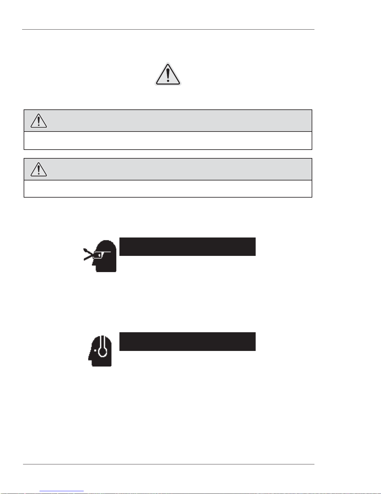
Figure 3-1. The photo shows the form tool configuration of the machine with the standard
self-centering mandrel.
Single-Point Configuration
The single-point machine is provided with a tool slide that feeds the tool radially across the face of
the pipe or flange. The slide is driven by a starwheel that engages trips on a ring mounted to the
machine housing. Bevels are performed using the Speed Prep auto-feed system, which automati-
cally feeds the machine axially as it cuts.
The single-point machine will perform facing or beveling of thick-walled pipes and flanges.
Chapter 3, Introduction to the Equipment: Overview of the EP424
E.H. Wachs Part No. 81-MAN-00, Rev. C 11
Figure 3-2. The photo shows the single-point configuration of the EP 424.
EP 424 Components
The following components are provided with the form tool configuration of the EP424:
• main drive assembly with lifting attachments
• feed assembly
• rotating tool head
• standard self-centering mandrel
• drive motor (air or hydraulic)
• hand tool set
EP 424 End Prep Machine
12 Part No. 81-MAN-00, Rev. C E.H. Wachs
The single-point configuration includes the following additional components:
• single-point slide
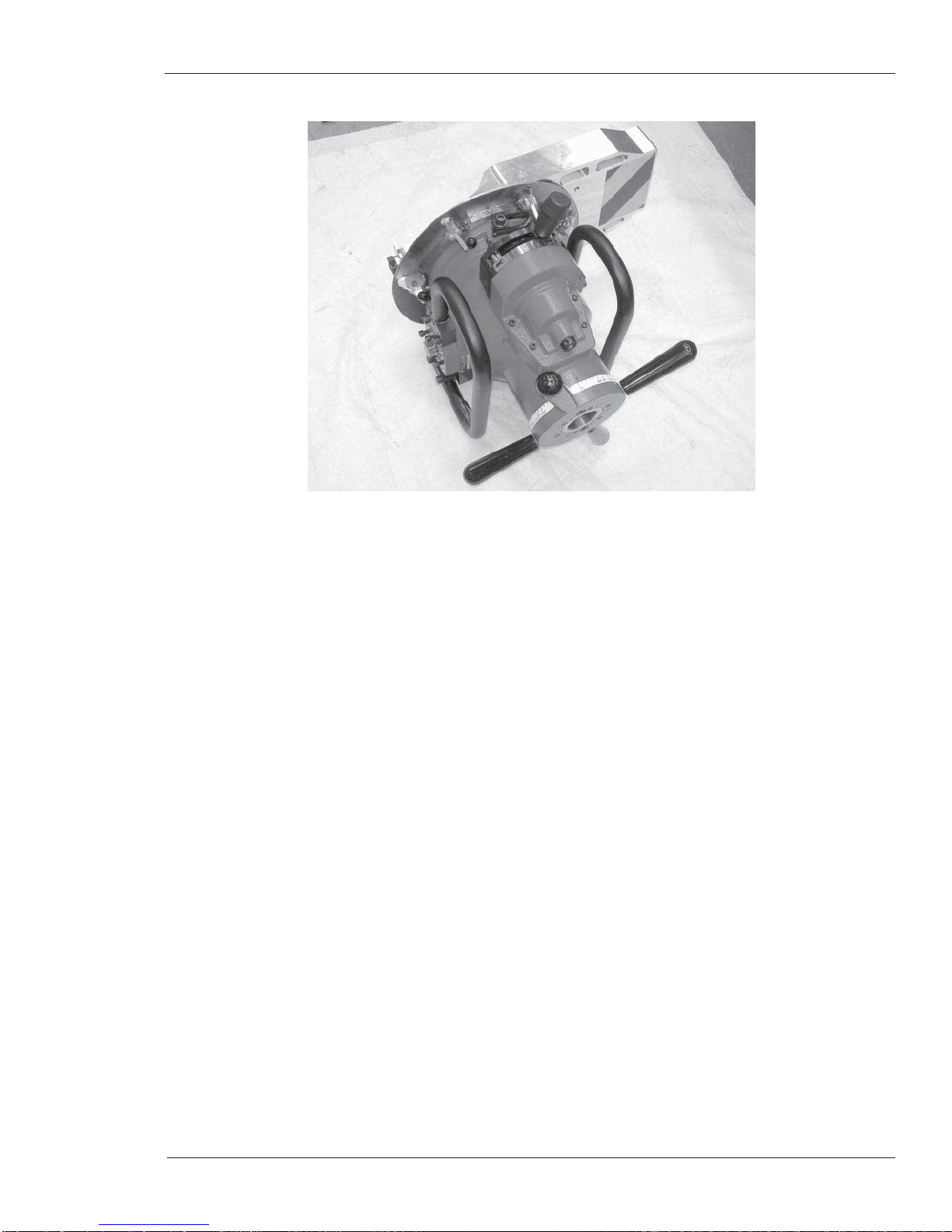
StarwheelFeed screws
Male tool slide
Tool holder
Feed gauge
Figure 3-3. The single-point slide feeds the tool radially across the pipe face. It is driven
along a feed screw by a starwheel.
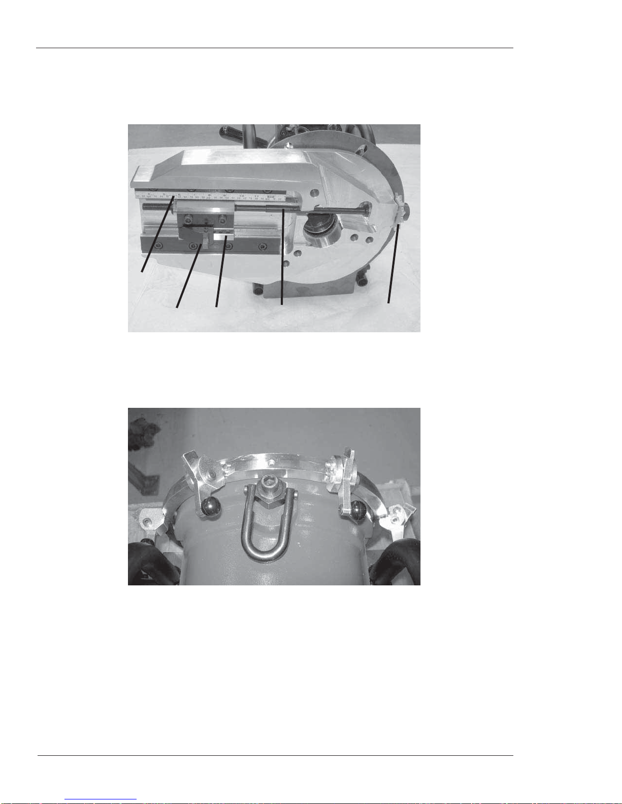
• radial feed trip assembly
Figure 3-4. The photo shows the trip assembly mounted on the main drive housing.

Chapter 3, Introduction to the Equipment: Overview of the EP424
E.H. Wachs Part No. 81-MAN-00, Rev. C 13
• Speed Prep autofeed module
Speed Prep
module
Figure 3-5. The speed prep module is installed on the main drive to operate the feed mecha-
nism for single-point beveling.
WARNING
The Speed Prep autofeed can feed the machine until it comes off the mandrel. Crushing or other serious
injuries could occur. Use the autofeed stop plate (81-316-00) to keep the machine from feeding too far.
• independent chuck mandrel
Figure 3-6. The independent chuck mandrel allows you to center the machine on the O.D. of
the pipe.

EP 424 End Prep Machine
14 Part No. 81-MAN-00, Rev. C E.H. Wachs
• extension leg kit for standard mandrel
Figure 3-7. Two sets of extension legs allow the standard mandrel to be mounted in pipes up
to 23.64” I.D.
• dial indicator assembly
Figure 3-8. The dial indicator is provided for centering the independent chuck in the pipe.
Table of contents


