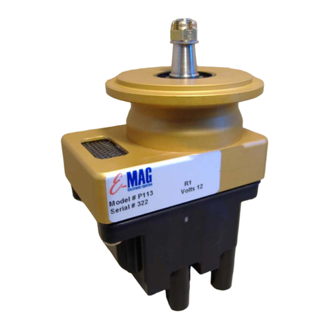
E-MAG 200-6XC Series Installation guide

–+
Product Documentation
Instruction Set for Continental™Styled
6 Cylinder EXPERIMENTAL Engines
Series 200-6XC
Installation and
Operating Guide
V 200-6XC .043
Continental Style

Changes to Manual: Changes, corrections, and supplements may be made at any time (see version number on
cover page –bottom right). Refer to E-MAG’s web page “Downloads” for the most recent version.
Alerts and Service Notes: Prior to installation and operation, review all applicable Alerts and Service Notes affecting
your equipment. See E-MAG web site https://emagair.com/service-notes/.
Experimental Aircraft Only: Series 200-6X ignitions are not certified and are not approved for installation on
certificated aircraft.
Warranty: E-MAG electronic ignitions are warranted for one (1) year from the date of purchase. E-MAG willrepair or
replace ignition modules within the warranty period that, in E-MAG’s sole opinion, have not been subjected to abuse
or attempted field repairs. This warranty is limited to the purchase price of E-MAG hardware and does not cover the
engine or other engine components that may be affected by defects or failure of the system. Do not attempt to open
or separate the ignition case sections. Doing so willvoid your ignition warranty.
CAUTION: The aircraft operator has the SOLE responsibility of determining how to appropriately and safely
configure and control engine and ignition operation. Nothing stated by E-MAG in this manual, its employees,
owners, agents, representatives, or affiliates should be construed as overriding or invalidating the engine
manufacturer’s instructions. E-MAG has NOT performed testing on the wide variety of engines in popular use and
cannot offer specific advice as to proper/suitable ignition configuration.
Notwithstanding engine manufacturer approval of certain engines to burn auto/alternative fuels, such endorsements
almost certainly presume operation with fixed magneto timing –and not variable firing electronic ignition. Operators
are SOLELY RESPONSIBILITYfor independently verifying proper engine behavior with standard and/or alternative
fuels including the ignition setup AS CONFIGURED BY THE OPERATOR.
Markings:
•The letter “C” or “L” indicating a model compatible with most Continental™or Lycoming™style engines.
•Or a full model number ending with letter C or L indicating compatibility with most Continental™or
Lycoming™style engines
o200-6XC
o200-6XL
•Other part numbers may appear in the same area (disregard).
System Serial Number - is etched into the electronics case.
When ignitions are serviced by the factory, a Service Sticker (roughly ¾” x ¾”) will be added that shows currently
installed circuit board and firmware.
Copyright© E-MAG Ignitions, all rights reserved 2023.
2014 Greg Street, Suite 112, Azle, TX 76020
Phone (817) 444- 5310

2
USING THIS MANUAL........................................................................................................................3
SHORT-CUT........................................................................................................................................4
INSTALLATION AND OPERATION...................................................................................................6
COCKPIT CONTROLS........................................................................................................................6
CONTROL PLUG WIRING..................................................................................................................7
SETUP AND CONTROL SWITCHES.................................................................................................8
LED AND TONE SIGNALS.................................................................................................................9
ENGINE ATTACHMENT.....................................................................................................................9
PLUG WIRES –CYLINDER ASSIGNMENTS.................................................................................10
AUTO PLUGS AND ADAPTERS.....................................................................................................10
MANIFOLD PRESSURE (MAP).......................................................................................................11
SETPOINTS.......................................................................................................................................12
SET IGNITION TIMING......................................................................................................................12
PULL-THRU TEST ............................................................................................................................15
TUNING MAX.....................................................................................................................................16
OPERATING NOTES........................................................................................................................18
MAINTENANCE.................................................................................................................................19
WIRING DIAGRAM............................................................................................................................21
APPENDIX 1 –SPARK PLUGS & ADAPTERS..............................................................................23
APPENDIX 2 - DELETED THIS MANUAL.......................................................................................23
APPENDIX 3 –TACH ELECTRICAL SPECIFICATIONS...............................................................24
APPENDIX 4 - INSTALLATION CHECKLIST .................................................................................25
APPENDIX 5: HARNESS FABRICATION (LEADS).......................................................................27

3
Using This Manual
This manual will include supplemental notes, comments, and tips that will appearas blue text.
Different versions of this manual are available for Lycoming™style and Continental™style
engines. Both versions can be downloaded from the E-MAGweb site.
Lycoming is a registered trademark of Avco Corporation.
Continental is a registered trademark of Continental Motors Group™.
Exercise care when handling the ignitions, engine, or propeller. There is a significant risk of burn,
electrical shock, injury, or even death. This manual may offer safety suggestions, but it is NOT to
be considered a complete list of the potential hazards, NOR is it presented as a complete set of
safety precautions that should be followed.
RISK OF EQUIPMENT DAMAGE: [***IMPORTANT***] Firing the ignition without all high voltage
loops in place, risks damaging the coils and/or electrical shock to the handler. If incurred, such
damage may not be immediately evident. High voltage loops include the circuit from a given coil
tower, to plug wire, to plug,to engine block, to companion plug, to companion plug wire, to
companion coil tower. Each pair of cylinders (1&2, 3&4, 5&6) constitutes a separate high voltage
loop.
ID
Date
Summary of Principal Changes
V 200-6X.31
5/25/19
Initial Product Release - disregard all previous materials.
Note: This ignition version includes two operating modes (fixed and variable
firing). Both modes share common position and processer-based control
logic elements. Redundancy is provided by having two autonomous
(left/right) ignitions, and up to three sources of operating power.
Experimental versions DO NOT have discrete logic circuitry for each mode.
V 200-6X.38
10/28/19
Simplified Setup procedure.
Simplified DIR checkand DIR change instructions.
MAX factory default now 9 degrees ahead of MIN.
Lycoming and Continental engine types now have separate instruction sets.
Added Quick-Start overview for re-installing.
Numerous other changes.
V 200-6X.39
11/12/19
Added option for straight spark plug boots/terminals if needed –primarily for
lower plugs on some Continental engines.
Added key parts to confirm prior to installation –see Quick-Start.
Reduced many of the required control wire sizes.
Revised starting instructions.
V 200-6X.40
7/28/20
Revised LR Denso spark plug number.
Mode Switch (optional for normally aspirated engines –1K resistors are pre-
installed in the factory switch
Revised routine for changing ignition direction (DIR)

4
V 200-XC.41
7/21/21
Clarified wording in Setup section.
V 200-XC.42
9/3/21
Correction to recommended LR spark plug stocking number.
Tuning tip: Customers reporting improved performance with MAX set 6-
degrees ahead of MIN.
V 200-XC.43
5/1/23
Suggestion for long primary battery cable runs (RV10s, canards, others).
Clarify: Pull-Thru test verifies bank firing order only. Cannot be used to check
tracking accuracy.
Revised wiring schematic
Firmware V55 and afterenables Fixed Mode starting, increased spark
energy, Fixed Mode fires at MIN vs previous version Fixed Mode firing at
default 20.
Factory default MIN will be between 20 and 22 degrees.
FW V58 improves transitions from external power off to power on.
Manual sections have been reorganized to better followinstallation flow.
Short-Cut
(Abbreviated Overview –New installers should review the entire manual.
Prior to installation, make sure you have the following items identified and on-hand.
•Suitable ignition mounting clamps. Some Continental™/Bendix style clamps (#535847)
have a shallow reach that will not provide suitable contact surface. Continental™clamps
#630535 (not stocked by E-MAG) have a longer reach and proper thickness –see Appendix
4.
•Fittings needed to connect ignition manifold pressure to your induction system. The
included (ignition side) MAP tubing and fittings can be replaced with other styles –installer
discretion –see Manifold Pressure (MAP).
•Identify your 14/28/48-volt power connection, fuse or circuit breaker, and power test switch
requirements - see Control Plug, Cockpit Controls, Wiring Diagram.
•Suitable automotive spark plugs –see Appendix 1.
Most Continental™styled engines rotate clockwise (viewed from back of the engine - looking at
prop on the far side). The ignition drive direction (DIR) will depend on the position of the ignition
mount in the accessory case. Series 200 6XC ignitions come pre-configured for top mounted (vs.
rear mounted) ignitions on clockwise rotating engines. Don’t worry - The setup procedure has
multiple checks to help installerseasily verify, and change when necessary, to insure proper
ignition direction (DIR). The first check starts by watching the ignition LED Color-Burst. In the first
½ second after power-up the ignition LED sequence will flash WHITE followed by RED or GREEN,
and then resume normal signaling. “C” (Continental™) designated ignitions have a factory default
White/GREEN Color-Burst –meaning DIR is set for a clockwise engine with overhead mounted
ignitions - continued below.

5
Before installing ignition - look at the vacant ignition drive socket while turning
prop in normal direction. For purposes of checking rotation (DIR) in Step 3 below:
CW rotation indicatesyou have a RED engine.
CCW rotation indicates you have a GREEN engine.
Note which type you have –red or green engine.
1) Mount Ignition: Insert the ignition(s) at any convenient orientation and tighten
mounting clamps to 17 ft/lb. Verify bus power and kill switches are both OFF,
then connect the Control Plug.
2) DIR Color-Burst: Power ON and watch for the LED Color-Burst code (first 1/2 second).
WHITE will be followed by either RED or GREEN. RED engines will want a White/RED burst.
GREEN engines want a White/GREEN burst. (see Setup)
a) If the Color-Burst code matches your engine - proceed to Step 3.
b) If Color-Burst code does not match yourengine - change DIR –see Note 1 below.
3) TC Setpoint: Move engine to TC with built-in TC Locator as follows: (If using other method to
locate TC, do so now and skip to Step 4 below. (see Setup for full description)
a) Remove spark plugs and move engine to #1 piston - bottom of stroke. Install Piston Stop
tool.
b) Verify buspower and Kill Switches are OFF. Press/hold the Config Button, while you turn
bus power ON. Continue the hold for six seconds until LED turns BLUE - then release. LED
will start blinking BLUE/GREEN to confirm you’re in TC Locator mode, where the following
processes are enabled.
i) Rotate engine to gentlyarrive at first piston stop –quick-press Button.
ii) Reverse engine movement to gently arrive at the second stop –quick-press Button.
iii) Remove Piston Stop tool and continue movement in the second stop direction to reach
TC, signaled by RED LED with tone.
c) Press/hold Button for six seconds, until LED turns WHITE –release button. TC is now
stored. Ignition will re-boot in normal mode and settle at YELLOW LED with tone (i.e. TC
position).
4) Check or Change MIN and MAX: Move prop to MIN and MAX positions to confirm or adjust as
appropriate (see Setpoints and Setup):
a) MIN (BLUE LED) matches engine manufacturers recommended magneto firing angle.
Default MIN is in the 20 to 22-degree range.
b) MAX (WHITE LED) marks the maximum cruise firing angle. Default MAX is 9-degrees
before MIN.
5) Basic Setup is complete. Finish installing plugs and plug wires, MAP plumbing, blast tube
cooling, and do the Pull-Thru test. See details for each later in the manual.
Note 1: Change DIR
1) (Firmware V52 and after) Position engine so ignition is at the currently stored TC (YELLOW
LED with tone), then press and hold Button for 6 or more seconds. The LED will flash red

6
during the hold, then flash WHITE (release Button), then automatically re-start with a color-burst
(WHITE then RED or GREEN) that signals the new DIR setting. Changing DIR will restore
factory default TC, MIN, and MAX settings. Return to Setup Step 3.
2) (Firmware prior to V52) Return to E-MAG forfirmware update.
After Setup, correct DIR setting is further confirmed by:
1) Engine (prop) movement to the region before TC will produce MIN and MAX (BLUE/WITE)
LED signals and tone sounds at 20 and 25-degrees (reference tones). If instead, they appear in
the 20 to 25-degree region after TC. –DIR is set for the wrong direction. Correct by changing
ignition DIR.
2) The Pull-Thru test (highly recommended) will fire plugs only when engine is pulled thru in the
programmed direction (DIR). Plugs will not fire if the engine is pulled in the wrong program
direction. Correct by changing ignition DIR and repeat setup.
Note 2: TIP if installing alone. It may be difficult to press/hold the Config Button and, at the same
time, reach the power switch. Disconnect the Control Plug, then turn bus power ON, then
press/hold the button while you re-connect the Control Plug (i.e., turn bus power ON).
Note 3: While checking MIN and MAX setpoints you will notice the ignition sounding a tone signal
at the 20 and 25-degree positions. They are provided as a positioning aid only. They are fixed and
do not move if you change MIN or MAX setpoints.
Installation and Operation
Cockpit Controls
1) Circuit breakeror fuse (one per ignition).
2) Ignition kill switch can be either:
a) Rotary switch OFF/R/L/Both/Start.
b) Toggle switch UP/ON and DOWN/OFF.
3) Ignition power test switch (Note 1) is for testing ignition internal alternator –see Ignition Checks:
a) Ramp Checks - a basic ignition alternator check.
a) Cut-Out test –a stress test for ignition alternator and overall system to determine the low
speed operating boundary. Should be done after installation, annual check, and after major
maintenance.
4) Mode Switch FIX/VAR:
a) Required on all boosted engines.
b) It is optional on non-boosted engines - see wiring diagram at end of manual.
Note 1: The internal alternator power test circuits can be configured several ways and is largely a
matter of builder preference. That said, the two controls involved (kill switch and power test switch)

7
can be located next to each otheron the panel, making these tests one-handed, intuitive, and more
ergonomic. Two examples are shown below the Wiring Diagram at the end of this manual.
Control Plug Wiring
1) Plug Styles:
a) Standard circular Mil plug connector (PT06A-10-6S-SR or similar). This is a solder
connection style plug with built-in strain relief clamp for attaching (20 AWG) control wires.
Note: Standard plug is roughly ½” longer than the optional potted plug (below) - in case
clearance is tight.
b) Optional circular plug connector with pig tail –circular connector (PT06P-10-6S or similar)
with 96” of wire soldered and potted – see color references below and wiring schematic at
the end of the manual.
2) Pinouts:
a) Pin “A” on circular plug (Pig-Tail red wire) - connects to your 14, 28, or 48-volt aircraft bus
–20 AWG - see Note 8. Route through a power test switch and suitable circuit protection.
Possibilities are:
i) A separate 5-amp fuse and separate power test switch.
ii) A 5-amp switchable circuit breaker, which can satisfy circuit protection and power test
duties.
b) Pin “B” (Pig-Tail black wire) - connects to the cockpit panel ground –20 AWG.
c) Pins “C” and ”D” (Pig-Tail white and green) –stow for future use –22 AWG.
d) Pin “E” (Pig-Tail yellow wire) - connects to your cockpit kill switch (p-lead ignition
ON/OFF). To turn ignition OFF, ground the p-lead with the switch. To turn ignition ON, un-
ground the p-lead Kill Switch (*) 22 AWG.
e) Pin “F” (Pig-Tail blue wire) –connects to tach instrument (3 pulses per rev) 22 AWG
(*) Mode Switch (optional): Ignitions can work with a
cockpit switch to select either Fixed Mode or Variable
Mode operation. The switch circuit adds a 1K bias
signal to the existing killwire (pin E) to enable Fixed
Mode operation. The switch E-MAG offers is a SPDT
(one switch controls two ignitions) with 1K resistors pre-
installed. Mode Switch is optional on normally
aspirated engines butis required on boosted engines.
Note 1: Shower or vibrator type starting aids are not compatible and may damage your E-MAG –
remove before installation.
Note 2: E-MAG p-lead wire does not make radio noise and does not require shielding. If replacing
a magneto, your existing shielded p-lead wire can be re-used. If doing so, the outer shield needs to
be trimmed clean and kept well clear of all otherterminations.
Note 3: All E-MAGs are “starting ignitions”. In a dual installation, or if replacing a non-starting
Circular plug (ignition)
Circular plug (cable)

8
magneto, revise your starting procedures, and/or remove any key switch starting blocks (remove
the jumper on the back of the key switch) to your E-MAGs.
Note 4: Whenever the aircraft bus is powered ON, the ignition is “awake”. It draws a small amount
of current (approx. 40 milliamps) even when not firing plugs. Use the master bus switch (or
breakers if necessary) to power down the ignitions when not in use.
Note 5: Do not power the ignition ON when you have a ground battery charger connected to the
bus. Pulling the breaker will isolate the ignition when charging.
Note 6: Collect your tach signal from only one ignition unless your instrument has provisions for
two (separate) tach inputs. Unlike a magneto, E-MAGs produce a tach signal even when kill switch
is turned to OFF.
Note 7: Tach signalis a 3 pulse/rev, low true, 33% duty cycle, 10-12-volt pulse - see Appendix 3..
E-MAG’s tach output is a courtesy feature, unrelated to the ignition’s primary purpose. Due to the
variety of instrument options available, our ability to support and troubleshoot interface issues is
limited.
Note 8: Longer cable runs to a remote main battery* may need to access bus power through a
dedicated 16 AWG cable connected directly to the battery.This will avoid sharing a long power
cable with the starter motor, a combination that can exaggerate power dips during startup and
inhibit ignition operation when cranking.
*Typical in RV10s, some canards, and others.
Setup and Control Switches
1) Configuration Button (“Button”) is located beneath a black plastic screw cap on the end face
of the ignition. The Button is used to set TC, move MIN/MAX setpoints, or change ignition DIR.
2) Mode Switch (optional) –Fixed Mode orVariable Mode can be selected by a single cockpit
Mode Switch that directs both left and right (Series 200) ignitions. Fixed Mode is enabled when
the Mode Switch applies a 1K bias resistance to the kill circuit(s). The Mode Switch can serve
one or two (Series 200) ignitions. The Mode Switch is required for all boosted engines. For
non-boosted engines the Mode Switch can be eliminated, in which case the ignition will operate
in Variable Mode only.
a) Fixed Mode - Mode Switch “FIX” will fire plugs at the MIN firing position. RPM must be
above cranking speeds–i.e. you cannot start in Fixed Mode. [In FW V55 and after, Fixed
Mode starting is enabled]
b) Variable Mode - Mode Switch “VAR” allows RPM and MAP inputs to select a plug firing
position between the MIN and MAX boundaries.
3) Power Test Switch - A cockpit power interrupt switch will be used to test the ignition internal
alternator. A switchable circuit breaker or separate test switch can perform this function. –see
Wiring Diagram
4) Kill Switch (p-lead switch) - The traditional cockpit ignition ON/OFF (Left/Right) test switch is
unchanged. The Mode Switch does not interfere or alter Kill Switch operation. The Kill Switch

9
OFF position connects the E-MAG kill wire (p-lead) to ground. The ONposition un-grounds the
kill wire. Note: All other connections from previous installations (tach, shower of sparks, etc.)
must be removed from kill switch wiring.
LED and Tone Signals
1) RED LED indicates CAUTION. When ignition
is powered ON and killswitch is ON the unit is
capable of firing plugs (“HOT”).
a) Steady RED indicates Variable Mode HOT.
b) Blinking RED indicatesFixed Mode HOT.
2) Other LED colors are enabled byturning kill
switch to OFF (ground p-lead). Plug firing is
blocked when displaying other colors.
a) Background color is GREEN.
b) Setpoints:
i) YELLOW* (with tone) signals ignition TC
setpoint.
ii) BLUE signals MIN setpoint, the lower end of the firing range in Variable Mode or the
fixed firing position in Fixed Mode.
iii) WHITE signals MAX setpoint, the upper end of the Variable Mode firing range.
3) Tone will sound at:
a) The stored ignition TC position (with YELLOW LED).
b) Ignition 20 and 25-degree positions. Tones are for the sole purpose of helping installers
locate their chosen MIN and MAX setpoints. After setting TC, these tones will flag the 20
and 25-degree positions –see Fig A. Other positions (18, 22, 35, etc.), if needed, can be
interpolated from these fixed reference locations.
* YELLOW is a composite color where LED elements produce a dull and slight shimmering yellow
effect.
Engine Attachment
First, verify the clamps you have are suitable for the E-MAG flange. E-MAG flange is 0.19” thick -
not suitable for 0.31” clamps.
1) Two studs, one above and one below each ignition station.
2) Mounting clamps fit over each stud to secure the ignition flange (and fiber gasket) to the case.
Alternately tighten upper and lower clamp (nuts) to 17 ft/lb. Note: Some Continental™/Bendix
style clamps (#535847)have a shallow reach that will not provide suitable contact surface.
Continental™clamp #630535 (not stocked by E-MAG) have a longer reach.
FIX/MIN (blue)
Background
LED color is
GREEN.
MAX (white)
Orientation will flip for
installations rotating in
opposite direction
(DIR).
Fig A
TC (yellow/tone)
Tone Positions:
Tone with yellow
LED at TC.
Tone (no LED) at 20
and 25-degrees,
serving as a general
position reference.

10
Plug Wires – Cylinder Assignments
As with any wasted-spark ignition, E-MAGs fire spark plugs in pairs. Cylinders 1&2, 3&4, 5&6 are
pairs with plug leads connected to both ends of a double ended coil “Bank”. See Appendix 5 for
instructions on fabricating individual trim-to-fit plug wires.
.
Note 1: The Pull-Thru test [highly recommended] is the best way to verify the installation follows
correct bank (cylinderpair) firing order. This test uses encoder data at the lowest possible
resolution, i.e., pull-thru firing positions cannot be used to check tracking accuracy. During
normal operation, dynamic quadrature counters are used to increase tracking resolution and
accuracy.
Note 2: Ignition Bank firing sequence is A-B-C regardless of the direction of the engine/ignition drive
interface.
Note 3: * CW and CCW engine rotation reference –as viewed from back of engine looking to prop
on the far side.
Note 4: If using strap (Adel) clamps to secure plug leads, make sure the clamps are properly sized.
Reusing clamps for smaller size (previous) wire maybe too tight and crush/compromise the internal
silicone insulation layer of our 8mm wire.
Auto Plugs and Adapters
Aircraft engines are typically tapped for 18mm thread spark plugs. To use 14mm automotive style
plugs, we sell Auto Plug Adapters. There are numerous auto spark plug styles and temperature
ranges available through various outlets. E-MAG has NOT studied the relative durability or
performance of different plugs. Customers need to monitor plug condition and evaluate and adjust
as necessary. The plugs listed in Appendix A and have a history of good service. Set plug gaps at
0.030” to 0.035”.
Bank A
Bank B
Bank C
Continental™engines:
1) Always - route Bank A to cylinders 1&2.
2) Most installations will route Bank B to 5&6, Bank C to 3&4
as shown.
3) In the event of a Left (CCW*)rotating engine (i.e. for a twin)
you may need to swap Bank B and C assignments
Always verify proper firing with the Pull-Thru test.
1
2
3
4
5
6

11
Long Reach (LR) vs. Short Reach (SR) Cylinders
Cylinders are made with two different spark plug thread depths. Match
spark plugs and plug adapters to the cylinder depth when ordering.
1) LR or SR cylinders can be identified by the aircraft spark plug call-out
for the particular engine. If it has the letter “M” - as in REMXXX, you will
need SR plugs and adapters. If it has the letter “B” as in REBXXX, you will need LR or LRX
plugs and adapters.
2) The thread lengths of plug adapters are as follows:
a) Short Reach (“SR”) external threaded section is approx. 1/2”.
b) Long Reach (“LR” and “LRX”) external threaded section is approx. 3/4”.
LRX adapters have extended hex heads to facilitate removal from some certain engines (550s and
maybe others) where the plug seat area is recessed and too tight for standard sockets. When
needed, you must specify LRX adapters when ordering.
Spark Plugs - See Appendix 1 for specific spark plug recommendations.
IMPORTANT: Remember to FIRST install each spark plug in the adapter (fully seated and finger
tight). THEN, insert the combined plug/adapter assembly in the engine and tighten to 18 ft/lb
(standard auto plug torque) through the spark plug ONLY. Do NOT torque the adapter itself. If you
torque the adaptersdirectly, stress will be focused underneath the adapter head, and it can fail
during installation. Such failures are not covered under warranty. Use anti-seize (sparingly) on the
outer/engine side of adapters. Auto plug manufacturersdo not recommend anti-seize on their
plugs.
Manifold Pressure (MAP)
The ignition comes with 3’ of 1/8”x1/4” silicone tubing, and a 1/8”
barbed nipple to 1/8”NPT brass fitting (packed separately), for use in
connecting manifold pressure. You could also use the female 1/8”
NPT in the ignition to attach yourown larger MAP hardware if
preferred. The ignition has both electronic and mechanical MAP pulse
dampening built in.
Normally aspirated engines: With normally aspirated engines, the
MAP tube is a fail-safe input. Meaning if the MAP plumbing comes
loose or fails, plug firing in Variable Mode will automatically retard to a
very flyable, but slightlyless efficient, firing position. If installing two ignitions, run a single MAP tube
to the accessory area, and then tee the MAP line to each ignition. If you have a manifold pressure
gauge, tee into that existing line for yourpressure source.
Boosted engines: With turbo normalized or boosted engines, MAP plumbing is NOT considered
fail-safe. A MAP plumbing failure can, in certain conditions, call for more ignition advance than is
SR LR LRX
MAP-1/8” Barb
(shown) or 1/8
NPT if brass fitting
is removed.

12
appropriate or safe. Excess advance can result in loss of power, overheating, and/or damage to
the engine. For this reason:
1) The MAP plumbing for two ignitions should be separate. A plumbing failure on one side would
affect one –not both ignitions.
2) The cockpit Mode Switch (required forboosted engines) is a simple and effective override that
will bypass the MAP input (plumbing failures)and set the ignition to Fixed Mode firing (where
MAP input is not a factor) –see Mode Switch elsewhere in this manual.
Setpoints
(Reference drawing Fig A)
1) TC (YELLOW LED - with audible tone) signals the ignition top center position.
2) MIN (BLUE LED) –A firing reference set to match engine mfg. recommended (magneto) firing
angle - typically 20 to 25 degrees before top center:
a) Marks the low advance (high power) end of the firing range in Variable Mode.
b) Also marksthe fixed firing position in Fixed Mode.
3) MAX (WHITE LED) –A firing reference that marks the high advance (cruise power) end of the
Variable Mode firing range. The default setting for MAX is 9 degrees ahead of MIN. Can be set
anywhere between 6 and 9-degrees before MIN.
4) DIR (not a setpoint per-se) –The ignition’s current operating direction (rotation) is confirmed by
various means throughout the installation process. (i.e. if it’s wrong the system will catch it later.)
Note 1: Anytime you move a TC, MIN, or MAX setpoint, reconfirm the stored setpoint positions of
all three. Some changes will restore the original factory default (override the custom setting you
last made). Setpoints should be stored in order –TC, then MIN, then MAX as shown
throughout the manual.
Set Ignition Timing
Factory rotation direction (DIR) will be pre-configured for overhead mounted
ignitions, but it needs to be confirmed. DIR is checked at several points
during the Setup process and is easyto change when/if needed. The first
opportunity to check DIR is prior to insertion.Lookdirectly into the vacant
accessory case ignition drive opening while turning the prop in the normal
direction. If the ignition drive socket turns:
•Clockwise - you have a RED engine (DIR color).
•Counterclockwise - you have a GREEN engine (DIR color).
1) Mount Ignition: Verify bus power is OFF and Kill Switch is OFF
(grounded). Turn ignition rotor by hand to align rotor lugs with rubber
cushions in the ignition drive socket. Insert the ignition (with gasket) and
secure mounting clamps finger tight. Rotate the ignition to any convenient orientation and then
tighten mounting clamps to 17 ft/lb.
2) DIR Color-Burst: Verify bus power and Kill Switches are all OFF. Connect the ignition circular
Control Plug and then turn bus power ON. LED will provide a Color-Burst sequence (in the first

13
½ second) that ends with WHITE, followed by either RED or GREEN, and then transition to
normal color signals. RED engines will look for a white/RED color burst. GREEN engines will
look for a white/GREEN color burst. Turn bus power OFF.
a) If the DIR Color-Burst matches your engine - proceed to Step 3. If it doesn’t - change DIR –
see Note 1 below.
3) TC Setpoint: Storing ignition TC Setpoint first entails moving the engine to its TC position.
Other methods (Note 1) can be used, but we recommend the procedure below. If using other
methods, do so now and skip steps a) and b) ii, iii, iv [*keep b)i) and b)v)]. Otherwise, locate
and store ignition TC as follows (TC Locator mode):
a) Remove spark plugs from Bank A cylinders #1 and #2. Engine movement will be easier and
safer if you also remove one plug fromeach of the other cylinders. Move the engine so
piston #1 is near bottom of the stroke. No needto track #1 compression –either stroke will
work.Insert the threaded piston stop tool in either plug hole of cylinder #1.
b) Verifybuspower and Kill Switches are both OFF.
i) *Enter TC Locator mode: Press and hold the Config Button while you turn bus power
ON. Continue hold (roughly six seconds) until LED turns BLUE - then release. The LED
will turn BLUE with a periodic GREEN pulse, confirming you are now in TC Locator
mode where the following interactions are enabled.
ii) Slowly rotate the prop in either direction until the piston gently contacts the stop (first
stop). Quick-pressthe Button and the LED will switch to GREEN with a periodic BLUE
pulse.
iii) Slowly rotate prop in the other direction until the piston gently contacts the stop (second
stop). Quick-pressthe Button and the LED will switch to steady GREEN, indicating the
ignition has calculated the TC (and 180-degree) positions. Keep bus power ON.
iv) Remove the stop tool. Backing the prop (piston) away from the stop will make it easier
to unscrew. Then continue prop movement in the last (second stop) direction. The LED
will turn RED and sound tone (RED/tone) when you arrive at engine TC position.
v) *SET TC: Press/hold the Button for six (6) seconds and the LED will flash WHITE -
release button. TC is now stored, and the ignition will automatically re-boot in normal
mode. The LED will settle at steady YELLOW (with tone), indicating the ignition is at the
stored TC position.
Note 1: Other methods to locate TC include the manufacturers “flower pot” method or move engine
to match TC of a previously set E-MAG on the other side.
4) MIN (BLUE) and MAX (WHITE) setpoints:
a) Check setpoints by positioning prop (engine) tothe MIN and then the MAX positions.
Approaching setpoint positions with engine moving in the normal direction may help to
reduce gear lash
i) Confirm the MIN(BLUE) setpoint matches the engine manufacturers recommended
magneto firing angle. NOTE: Engine alterations that boost power (high-compression
pistons, induction mods, custom cams, enhanced fuels, etc. may require more
conservative (lower) MIN and MAX settings. The ignition default MIN is around 20 to
22-degrees before TC. Adjust as needed.
ii) MAX(WHITE) The ignition default MAX is 9-degrees ahead of MIN and can be re-set as
low as 6-degrees ahead of MIN.

14
b) Change setpoint positions (if needed) –see Note 5:
i) With the intended setpoint color showing (BLUE example) press/hold the Button.
ii) Continue the hold while you move the prop (engine) to the desired setpoint location.
iii) Then release the Button. The LED will remain (BLUE example), indicating placement at
the newly stored setpoint.
5) Basic setup is complete. Always confirm setpoints by rocking the prop back and forth over:
a) TC Setpoint to see GREEN –YELLOW/tone - GREEN - see Note 1.
b) MIN Setpoint to see GREEN - BLUE –GREEN - see Note 1.
c) MAX Setpoint to see GREEN - WHITE –GREEN
Prior to operation you need to connect plugs and plug wires, manifold pressure (MAP)
plumbing, and blast tube cooling –as appropriate. We also recommend doing a Pull-Thru test.
Details for each can be found elsewhere in manual.
Note 1: After Setup, correct DIR setting is re-confirmed by:
•Engine movement in the region before TC will produce MIN (BLUE) and MAX (WHITE) LED
signals and tone sounds at 20 and 25-degrees(reference tones). If instead, they appear in a
similar region after TC. –DIR is set for the wrong direction. Correct by changing ignition DIR –
see below.
•The Pull-Thru test (highly recommended) will fire plugs only when engine is pulled thru in the
programmed direction (DIR). Plugs will not fire if the engine is pulled in the wrong program
direction. Correct by changing ignition DIR.
Change DIR
•(Firmware V52 and after) Position ignition at TC (YELLOW LED with tone), then pressand
hold Button for 6 or more seconds. The LED will flash red during the hold, then flash
WHITE (release Button), then automatically re-start with a color-burst (WHITE then RED or
GREEN) that signals the new DIR setting. Changing DIR will restore factory default
MIN, MAX, and TC settings. Return to Setup Step 3.
•(Firmware prior to V52) With a steady GREENLED showing (normal background color),
press/hold Button for 10 seconds until the LED turns WHITE –release Button. Ignition will
store the change and re-start with a color-burst (WHITE then RED or GREEN) that signals
the new DIR setting. Changing DIR will restore factory default MIN, MAX, and TC
settings. Turn bus power OFF and return to Setup Step 3
Note 2: Make sure Kill Switch stays OFF until all high-voltage connections (plugs, plug-wires, coil)
are in place. Firing plugs without all high-voltage connections risks damaging the coil. After the
initial Color Burst at power-up, a continuous RED LED (flashing or steady) indicates ignition is
ON/HOT (ready to fire plugs). No Setup procedure requires ignition to be HOT. Power OFF
and examine/correct kill circuit.
Note 3: Take care with the rubber drive socket cushions when removing or inserting the ignition. If
they drop into the accessory case, retrieval can be problematic.
Note 4: Moving MIN or MAX Setpoints. The procedure for moving a MIN or MAX setpoint is simple
but strict in two respects:

15
•Make certain the Button press/hold is started with the setpoint color showing (BLUE or
WHITE) (i.e. not the background GREEN color).
•The “hold” must be uninterrupted until you reach the new engine position. If the Button hold
is relaxed in route, the setpoint will attach to an unintended release point.
Note 6: Top center and other engine position markings (TC, 20, 25, etc.) may be stamped on the
prop flange that will align with the lower engine case seam –see engine manufacturers
documentation.
Blast Tube Cooling
E-MAGs are designed for a high-heat environment, but there are still
thermal limitations and benefits to keeping the equipment as cool as
possible. Blast tube cooling is a simple way to reduce operating
temperatures, and we consider it mandatory (not applicable to top
mounted installations on the cold side of the engine deck). Blast
tubes should be directed at the round neck, immediatelybehind the
mounting flange.
The mere presence of blast-tubes does not guarantee they are
operable and/or effective. After initial operations, operators can
verify the ignitions are within temperature guidelines (under 200F
during flight). A thermal reactive label is installed on the electronics
case. Alternatively, a thermal probe can verify ignition case
temperatures at the forward section of the electronics (box shaped)
compartment.
Electrical System Condition
E-MAG’s power dip protection helps guard against severe voltage drops that occur when the starter
motor is engaged. However, in the event of a compromised electrical system (low battery, long
cable runs, corroded terminals, cold engine, etc.) bus voltagemay not rebound as the starter
speeds up (as is normal). A properly designed and functioning electrical system is essential for the
ignition to work properly. If bus voltage goes below safe levels while cranking, a built-in powerdip
safety circuit will not allow the ignition to fire (per design). The starter is the largest load on the
electrical bus. Keeping non-essential loads turned OFF while cranking will help. Note: We have no
definitive guidance, but there is some indication light-weight lithium batteries may contribute to
greater ignition voltage dips during startup.
Pull-Thru Test
The Pull-Thru test will confirm 1) plug wire assignments, 2)basic operation of firing circuits, and 3)
correct DIR as follows:
1. Remove all spark plugsfrom the engine and reconnect them to the plug leads.
2. *IMPORTANT* Rest each plug on the engine case or convenient location such that the
metal jacket of each plug is grounded to the engine block. Alternatively, the plug metal
jackets can be wired to the engine block or plugs can be bundled directly to each other with
metal jackets in direct contact of each other.
Blast target

16
3. One ignition at a time: Turn bus power ON, Kill Switch ON, and (if installed) Mode Switch to
VAR. LED will be steady RED. Rotate the prop by hand in the normal direction of travel
and confirm all plug pairs fire in proper sequence. Anydeviation indicates a wiring or setup
error.
•Both plugs for cylinders1&2 (Bank A)fire at the starting lag position (4 degrees after
TC).
•Both plugs for Bank B fire 120 degrees later –see Note 3.
•Both plugs for Bank C fire 240 degrees later –see Note 3.
Note 1: Plugs will not fire:
i) When the engine is rotated the wrong direction.
ii) If ignition DIR is not configured to match engine rotation.
iii) When Mode Switch is in FIX position and engine is moving at hand pull-thru speeds.
iv) Plugsfire only once per cycle. You cannot backup and fire them again. Keep pulling thru
in the normal direction.
Note 2: Multi-Strike. At cranking speeds, the ignition uses a (5) rapid strike sequence foreach
bank. This means the Pull-Thu Test will not produce the familiar single spark “click”. Instead, you’ll
hear the plugs “buzz” - the sound of a multi-strike sequence.
Note3: Due to the variety of engine and ignition configurations, it may be necessary to swap the
plug wire to cylinder (Banks B and C)assignments to achieve proper firing –per the engine
manufacturer firing order.
Note 4: Pull-Thru firing positions cannot be used to verify ignition tracking accuracy. It only confirms
proper wiring and circuit assignments.
Tuning MAX
Orientation:
Operating the ignition in Variable Mode (Mode Switch “VAR”) can improve engine efficiency by
enabling automatic adjustment of the plug firing advance. The range of automatic adjustment is
capped by the MAX setting. MAX will be either the default (9-degreesahead), or a lesser MAX
position (as low as 6-degrees ahead) as set by the operator.
TIP: Most Cont 550 customers are reporting improved cruise performance with MAX setting
reduced to 6-degrees ahead of MIN (vs. the 9-degree default).
Operators can monitor VAR mode cruise conditions (RPM above 2400 and MAP 22” or below)
where spark advance is greatest and be mindful of the engine manufacturer’s temperature
recommendations and red-lines. It should be understood that improving efficiency (extracting more
energy from a given amount of fuel) means a certain amount of additional heat may be generated.

17
Operators can anticipate VAR mode advanced firing to cause CHTs to rise by some increment and
EGTs to fall by some increment.
As a GENERAL FRAMEWORK ONLY, VAR mode operations (MAX adjustments) can be guided
by engine efficiencies (airspeed/fuel-flow) and CHTs at cruise power settings –keeping in mind the
limitations of CHT readings. Ignition advance is a significant, but not the only factor influencing
CHTs. Baffling, mixture, prop, cylinder design, cylinderbreak-in, air temperature, air density,
humidity, fueltype, induction boost, and more can all affect the indicated CHT. Every installation
should be considered unique –assume nothing.
Establish a baseline
An initial period of operation in Fixed Mode (Mode Switch to “FIX”after start-up) will allow youto
establish an operating baseline with plug firing at the manufacturer’s recommended (magneto)
firing position. Similarly, Variable Mode operation at high power (higher RPM and MAP 25” and
above) settings will fire at the same MIN/magneto position. The ignition will still provide higher
spark energy and that alone can have some effect on engine behavior. If temperature issues are
encountered under these conditions you might test with a slight reduction of MIN firing position,or
look into correction outside the ignition –baffling, fuel, etc.
Tuning Actions –Adjust MAX setpoint (affecting Variable Mode only)
1) Extending MAX past the 9-degree default will offer little additional benefit. The underlying
advance table itself (initial release models) is limited to 9-degrees. The ignition may reject
attempts to set MAX past this point.
2) Restricting MAX (move closer to MIN) will cap the advance range which should reduce
excessive cruise CHTs –if encountered. Note: Cont 550, and perhaps others, seem to favor
MAX setting closer to 6-degreesahead of MIN.
Tuning Objectives:
The goal is not to deploy the maximum amount of ignition advance possible. Rather, we’re looking
for the least aggressive range that maximize performance - and no more. Overly aggressive
settings don’t improve performance, but can increase temps and potentially damage the engine.
Adjust accordingly.
Note 1: Mode Switch - When you enable Variable Mode (Mode Switch “VAR”) to test MAX settings,
you always have the option of switching to Fixed Mode (Mode Switch “FIX”) and return to your
previously established fixed firing baseline. The Mode Switch can be operated at any time, other
than startup, when Variable Mode is required.
Note 2: Alternative (auto) Fuels: CAUTION - Notwithstanding enginemanufacturer approval of
some engines to burn auto/alternative fuels, such approvals almost certainlypresume operation
with fixed magneto firing - not high-energy variable firing electronic ignition. Operators need to
independentlyvalidate proper engine behavior with different fuels and adjust ignition as needed.
Generally speaking, auto fuel burns faster than avgas and is, in effect, a timing change. An
offsetting adjustment (lower advance) may be necessary for proper operation.

18
Operating Notes
Mode Switch
Start engine with Mode Switch set to VAR (plugs will not fire at cranking speeds in FIX Mode).
[Ignitions with FW V55 and after Fixe Mode starting is enabled]. The Mode Switch does NOT
replace or interfere with traditional ignition ON/OFF (p-lead/kill) switches. Rather, it’s a simple in-
flight controlthat switches between Fixed Mode (ON) and Variable Mode (ON).
Engine Management
The high energy sparkand variable firing of an electronic ignition will change engine behavior.
Starting:
1) Flooding can occur when excess fuel is introduced in the cylinders and is an issue for all types
of ignitions. High energy spark is more resistant to flooding, but there are limits to how much
can be tolerated.
2) Wasted spark ignitions (E-MAG and others) fire spark plugs in pairs.On any given cycle only
one cylinder, within a Bank pair, is in the compressed “firing” position. At that same moment,
the companion cylinder is between the intake and exhaust strokes with both valves open. A
wasted spark ignition will fire plugs in both cylinders within the bank. If sufficient fuel vapor is
present in the companion cylinder due to excess priming, throttle, mixture, or any other reason,
the companion chamber can ignite. This is called a “wasted side firing” and can send a
pressure pulse down the intake and exhaust pipes. It’s sometimes mistaken as a backfire or a
kick-back, which is different. Wasted side firing is remedied by adjusting your starting
procedure to reduce excess fuel.
To reduce the risk of both flooding and wasted side firing, we recommend you begin your search
for optimal start-up settings on the extreme lean side and gradually modify (increase throttle or
mixture) asnecessary to achieve quick and consistent starts.
Lean-limit and mixture control: The familiar lean-rough boundary experienced with magnetos
will shift (far leaner) or it may disappear entirely. This significantly alters the lean-rough boundary
and the seat-of-your-pants mixture control (lean to rough- then richen).
Ignition Checks: Your ignition checklist will be extended to include two new features, internal
alternator and Mode Switch (if installed). Both can be tested during your routine left/right Ramp
Check, but the alternator has an additional test (Cut-Out test) that is run on a different schedule.
1) Ramp Checks (roughly 1700 RPM):
a) Internal Alternator - E-MAG internal alternator operates in parallel with power supplied by the
aircraft bus. The ignition automatically transitions between aircraft power and internal
alternator power as needed. Aircraft power is required for starting and sometimes for low
idle speeds.
i) Running on one side only, turn ignition power test switch OFF for2-3 seconds and back
ON. The engine should run smooth during the outage –this verifies the internal
alternator is working.
ii) Repeat with the other ignition.
Any rough or degraded behavior indicates a problem - not suitable for flight.

19
b) Mode Switch (recommended, on all boosted engines) –Mode Switch will be set to VAR for
most operations and is required for starting.
i) Running on one side only, turn Mode Switch from VAR to FIX for 2-3 seconds and then
back to VAR. The engine should run smooth in both positions. The firing position may
change with Mode Switch transitions, so a slight shift in rpm might be expected.
ii) Repeat with the other ignition.
Rough or significantly degraded behavior indicatesa problem - not suitable for flight.
2) Cut-Out test should be done after initial installation, power plant maintenance, and at annual
inspection:
a) The Cut-Out test checks ignition condition and the entire system (see Note 1) in challenging
conditions. Internal alternator output will vary with engine rpm. You are verifying the system
is capable of operation without aircraft power at speeds below your in-flight idle. Your
ground idle can go much lower than your flight-idle, so the Cut-Out test is a ground based
(only) exercise.
b) Operating on one ignition, lower engine speed to 1200 rpm. Then cut bus power to the
ignition. A slightrpm my dip may be expected with lower spark energy.
c) Very slowly lower the engine rpm until the engine reaches low idle limit or quits. A log-book
entry can help track Cut-Out trends over time.
d) Repeat Cut-Out test on the other ignition and then with both ignitions.
Note 1: The Cut-Out test marks the low-speed boundary of the entire system (not just the ignition)
when the ignition is self-powered. Spark energy is a significant, but not the only factoraffecting cut-
out speeds. Mis-adjusted idle mixture fowled or partiallyfowled plugs, induction leaks, mis-adjusted
prop, and other factors can affect (elevate) cut-out speeds. Keep this in mind if ever investigating
the cause of elevated cut-out speeds. E-MAG bench tests every ignition to verifythey self-power,
open air spark, down to 700 rpm prior to shipment. This is well below most in-flight idle speeds.
Note 2: When performing a Cut-Out test, if the engine falters allow it to come to a stop and fully
power down. Re-applying bus power or activating the other ignition at the last moment to keep the
engine running may not restore full operation and is unlike the power boundary event we are
probing.
Maintenance
Condition Inspection (annual)
1) Confirm Setup reference positions (TC, MIN, MAX) prior to removal. Look for discrepancies (if
any) from prior settings.
2) Check E-MAG web site for the most recent Manual (www.emagair.com/downloads), Service
Notes (www.emagair.com/service-notes), to verify equipment is current with allupdates.
3) Ignitions come with a thermal sticker that will trip (turn from a light eggshell white color to gray or
gray/black) as case temperatures exceed 200 degrees (F). Dark gray or solid black indicates a
Table of contents
Other E-MAG Engine manuals
Popular Engine manuals by other brands
Z-RAY
Z-RAY 41-2486 manual
Oriental motor
Oriental motor RKII Series operating manual
Keyautomation
Keyautomation RAY Instructions and warnings for installation and use
woodmizer
woodmizer LT35 Safety, Operation, Maintenance & Parts Manual
CRRCpro
CRRCpro GP22R manual
airmaster
airmaster SI-001 Supplementary Instruction Booklet

