E-RM Multiclock User manual

USER MANUAL
E-RM ERFINDUNGSBÜRO

Copyright © 2018
e-rm erndungsbüro - https:/www.e-rm.de
E-RM Erndungsbüro Rest & Maier GbR
Wikingerufer 7
10555 Berlin
Germany
Version 1.1 - August 2018

Contents
1 The Purpose of the Multiclock 7
2 Machine Overview 8
3 Conguring the machine 10
3.1 ClockSource......................... 10
3.2 TimeSignature ....................... 10
3.3 ChannelSetup........................ 11
3.3.1 ShiftRange ..................... 11
3.3.2 Oset Calibration . . . . . . . . . . . . . . . . . 11
3.3.3 Channel Mode . . . . . . . . . . . . . . . . . . . 12
3.3.4 Channel Dividers . . . . . . . . . . . . . . . . . . 13
3.3.5 LFO Conguration . . . . . . . . . . . . . . . . . 13
3.3.6 Analog Conguration . . . . . . . . . . . . . . . 13
3.3.7 Midi Controller Conguration . . . . . . . . . . 14
3.3.8 Presets........................ 15
3.4 Advanced Settings . . . . . . . . . . . . . . . . . . . . . 15
3.4.1 System Setup . . . . . . . . . . . . . . . . . . . . 16
4 Using Audio Sync 17
4.1 Plugin............................. 17
4.2 SyncTrack .......................... 17
5 Using MIDI In 19
5.1 MIDIMapper......................... 19
6 Using USB MIDI 20
6.1 MIDI Forwarding . . . . . . . . . . . . . . . . . . . . . . 20
6.2 Parameter Remote Control . . . . . . . . . . . . . . . . 21
6.3 DAW Transport Control . . . . . . . . . . . . . . . . . . 22
7 Tips and Limitations 23
7.1 Nicetoknow......................... 23
7.2 AudioSync.......................... 24
8 Updating the System Software 25
9 Declaration of Conformity 26
10 Contact 27

Simply play together.

Introduction
Hello Stranger!
Congratulations for purchasing your multiclock. You have just
purchased an avant-garde machine: you are now able to solve sync
and timing issues in the studio and on stage once and for all.
This multi-format sync box builds a bridge between DAWs and
external MIDI, DIN/sync24 and analog modular gear. It allows tight
integration of external instruments into your digital production
workow without having to worry about timing.
Also as a standalone master clock generator for hardware-only
setups it cuts a dash. Start shifting your clocks, start shuing the
beat, we are sure you will enter unknown territories.
Please read this manual carefully and follow the advice to be re-
warded from the beginning with a great and powerful tool. And be
assured, the multiclock is a game changer!
Have fun and start making music,
The team of E-RM


The Purpose of the Multiclock
The multiclock is a multi-format sync box which is built to overcome
all well known problems with tight synchronization of external
sequencers, drummachines, arpeggiators and other external gear
with each other and especially in the workow with a DAW.
The key feature of the multiclock is it’s ability to derive a variety
of sync signals from a special Audio Sync track instead of using for
example a MIDI Clock signal.
With this technique, the multiclock is able to generate MIDI 20.83 μs is the length of one sample at
an audio sampling frequency of 48 kHz
Clock, DIN/sync24 and analog modular clock signals to sync your
slaves with a jitter as low as ±20 μs. This nally ensures seamless
integration of all of your external instruments with your computer.
The second important feature of the multiclock is it’s ability to
shift all output clock channels against each other and relative to
the master clock back and forth in realtime. Up to ±300 ms of shift
range ensure easy compensation of machine delay, audio buer
latencies and leave more than enough headroom to shift just to
get the groove.
The multiclock is not built to be syncronized by a master DAW using
MIDI or USB MIDI, nor does it correct your MIDI Note timing; it
probably also can not y to the moon.
But instead you can nally start bending time, play with the
phase of your sounds and adjust microtiming of your arrange-
ments. Let’s start today, it’s a lot of fun!

Machine Overview
The front panel of the multiclock can be roughly divided into a
real-time and a conguration section.
On the left half, there are four identical channel stripes for real-
time control of each output channel. They consist of a shift and a
shue knob, a status led and a start/stop button.
Shift knobs feature a center detent to easily set the channel
oset to the zero position. The status leds light up in dierentStatus leds ash green for activated
and shine red for running channels. colours to indicate running mode during playback or highlight the
current channel under conguration.
On the right half, you can nd the conguration display, a rotary
encoder with click to navigate the menus, a function key and a BPM
led. Moreover, global start/stop buttons are available for playback
control when running on the internal masterclock.
During normal operation, the display presents all signicant infor-
mation on the homescreen.
multiclock front panel overview.

machine overview 9
You see the clock source, time signature and current BPM on the
right part of the screen.
On the left part is one line for each output channel to display
shift oset, shue amount or additional information like channel
mode and LFO waveform.
On the bottom of the screen is a virtual button section which
allows you to change the global machine conguration. Use the se-
lect menu button to toggle the cursor between the virtual buttons
and the upper main part of the screen.
Example Homescreen. Notice the
dierent Channel Modes shown here:
Channel 1 is congured as LFO, Channel
2+3 work in sync mode and Channel 4 is
used as a MIDI controller.
The rear panel of the multiclock provides connectivity and input
for the power supply. It can also be divided into two sections:
inputs on one side, outputs on the other. DC input and a power
switch are located on the rightmost edge.
Syncronisation inputs are available in the form of a ¼” jack for
Audio Sync and a DIN socket for MIDI, sync24 and analog modular Modular Synth connectivity is eas-
ily accomplished by using a E-RM
modular whip to convert from all DIN
sockets to 2 mini jacks for clock & run
signals.
sync. Audio Sync can be fed as a balanced or unbalanced signal but
is internally treated unbalanced in both cases.
On the left, there is one DIN socket for each output. Any of them
can provide MIDI, sync24 and analog modular sync, depending on
the channel settings in the menu.
Channel 1 additionally has a ¼” TRS output jack to provide ana-
log clock or analog LFO. Tip = Clock/LFO, Ring = Start
Channel settings can be reached by holding the set channel
button and pressing the button of the respective channel.
multiclock connector overview.

Conguring the machine
Conguring the settings of your multiclock is as easy as following
the menu on the screen if you keep two things in mind:
• The screen is always divided into a main and a bottom section.
To toggle the cursor between both sections, simply push the
select menu button.
• Turn the encoder to move the cursor or change settings. Click it
to select an option or submit a change.
Clock Source
Before using the multiclock in your setup, probably the most im-
portant setting is the selection of the clock source. You can reach
the conguration page from the homescreen by selecting the SRC
button.
Clock source selection. USB MIDI
channel can be chosen after selection.
Choose between several input formats or use the internal mas-
terclock generator. The recommended way to syncronize external
gear to a DAW is using Audio In and the plugin provided on our
website. Please refer to section 4 (p. 17) for further instructions.www.e-rm.de/downloads
Time Signature
To be able to start slaves always in sync with the downbeat of the
next bar, the multiclock needs to know which time signature you
are playing in. Select the T.SIG button from the homescreen to

conguring the machine 11
get to the respective conguration page. Set all machines in your
setup to the same value.
You can change the signature from 3/8 to 32/8, changes are
saved automatically.
Conguration of Time Signature.
Values are shown in reduced fraction
form beneath.
Channel Setup
All changes concerning the dierent channels are congured on
the Channel Setup pages. You can reach each channel’s setup page
by holding the set channel button and additionally pressing the
button of the respective channel.
Shift Range
Channel Setup Page. Notice the preset
name on top of the screen.
Shift Range congures the min/max value of shift amount that All knob ranges are internally divided
into 1000 steps. You should always t
the shift range to your usecase to gain
best performance.
you can reach by turning the shift knob to the limits.
You can lock and unlock the shift parameter of each channel dur-
ing playback (and only during playback!) to brace yourself against
unintended knob movement. To do so, simply hold the set chan-
nel button and push the button of the channel you intend to lock.
The channel number on the homescreen is replaced by an ”L” to
indicate locking status.
Oset Calibration
To compensate audio delay of connected slaves, buer latency
of software monitoring or other sources which cause a constant
oset to a channel, you can set a constant oset as the channel’s
zero position.

12 multiclock - user manual
Oset calibration process is initiated by selecting Offset inIt is recommended to program a
simple percussive sound on every full
note of the machines involved in the
calibration process.
the menu. You are asked to start the clock source rst. If you are
using the internal generator, please press the global play button,
otherwise start the master clock.
First, adjust the oset roughly until both sounds play at the
same instant. Afterwards you can get into microtiming by holding
the set channel button and adjust in steps of 20 μs.
Oset Calibration. Used to set the zero
position in time for each channel.
Change the value until you are happy with the result. Stop the
master clock and submit your value by clicking the encoder.
Channel Mode
Each channel can be congured under Chn Mode to emit either
MIDI Clock (MIDI), DIN Sync/sync24 (DIN) or analog modular clock
(Analog).
If MIDI is selected, a sub-menu is available to enable Song Posi-
tion Pointer forwarding. In this mode, song position data received
on either the physical MIDI In or via USB MIDI is forwarded to the
selected channel. Make sure to send SPP information only to one
of the four USB MIDI ports or DIN MIDI In.
Enable MIDI Song Position Pointer
Forwarding for a MIDI output channel.
Correct osets are added to compen-
sate the 1 bar count in for POS/NEG
mode.
Unused channels can further be used as a MIDI controller (Ctrl).
A special function is available on Channel 1 which features an ana-
log LFO on it’s TRS output jack (LFO).

conguring the machine 13
Channel Dividers
Clock dividers are fun to create polyrhythmic patterns, thus you
can set them on all output ports.
Channel Divider Conguration.
For MIDI and DIN, you can set Chn Divider to Knob and use the
shue knob anytime to change the divider between 1,2,3 & 4.
For Analog mode, you can either set Chn Divider to Knob to Please note that due to the internal
structure of the algorithms, in analog
mode shue only sounds with a
divider of 1 and 6 like you are used to
it; but try other dividers with shue,
they return interesting results!
use the shue knob to change between 1, 3, 6, 8, 12, 16, 24 & 32
on the y or set an integer value between 1-96 directly.
A change of the clock divider by turning the knob during play-
back is always carried out in sync with the next bar. Shue is
automatically set to zero in all modes when Knob is selected and
the current divider is shown instead of the shue value on the
homescreen.
LFO Conguration
When Chn Mode is set to LFO on Channel 1, a syncronized analog
LFO signal is emitted on the tip of the ¼” TRS output jack.
LFO Conguration.
The waveform can be selected between Saw Up,Saw Down,Sine,
Pulse and Random and is displayed on the homescreen. The LFO The LFO is obviously also completely
shiftable in time. Try it, you will like it!
Frequency is changed during performance with the shue knob. It
is either free running (free) and reset on every new bar or quan-
tized to t the current tempo (quant).
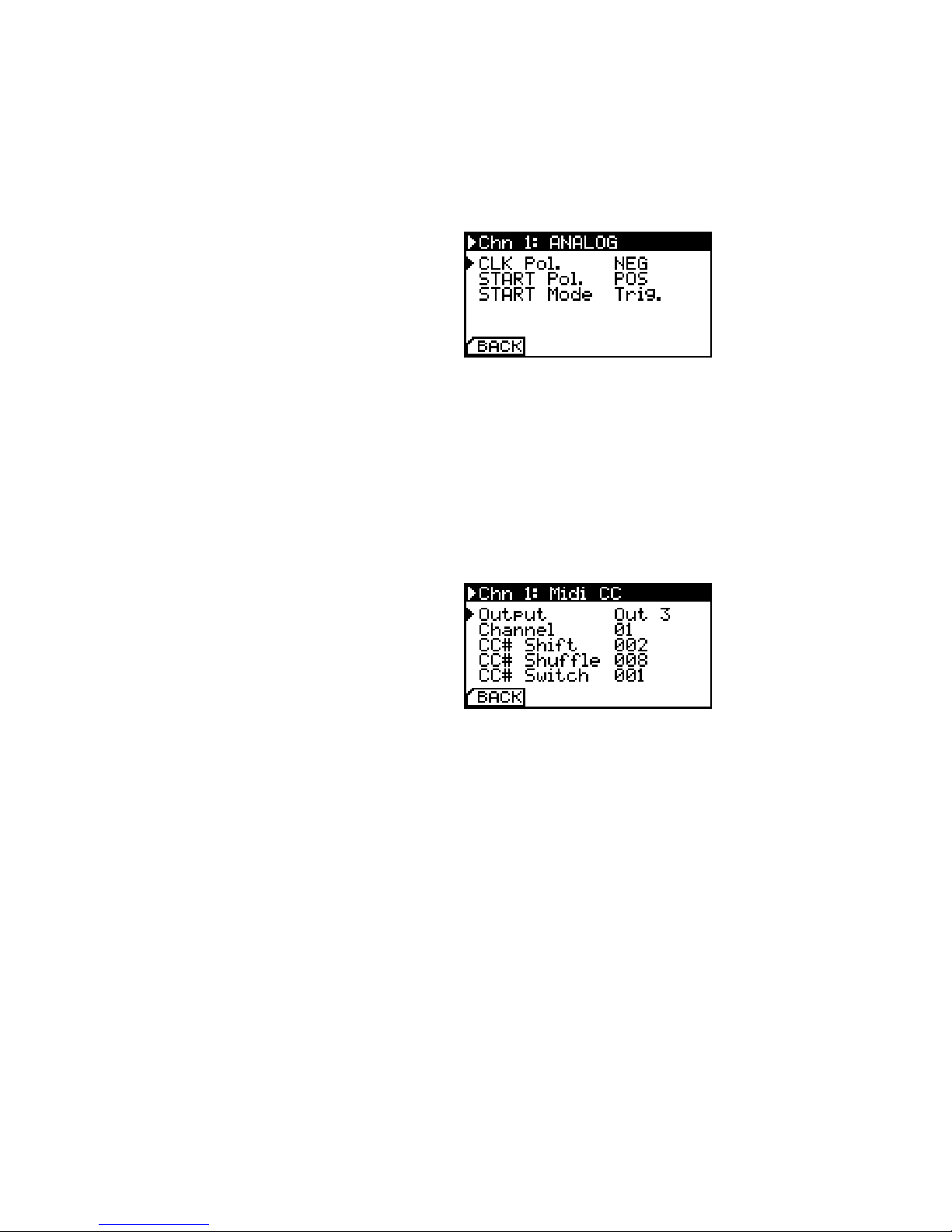
Analog Conguration
Due to an enormous variety of clock polarities, start/stop be-
haviour and necessary dividers in the modular world, you can fully
congure all settings when Chn Mode is set to Analog.
14 multiclock - user manual
START Mode can be set to emit a trigger pulse (Trig.), optionally
skip the rst clock pulse after start (Trig sk) or simply act as a gate
(Gate). Be sure to check your modular sequencers manual if you
are in doubt.
Analog Conguration. This mode can
also be used with DIN Sync instruments
to implement clock dividers.
Midi Controller Conguration
If you happen to have unused clock channels on your multiclock
and need a basic MIDI Controller for one of your synths, simply
congure the knobs to emit MIDI Control Change commands by
setting Chn Mode to Ctrl.
Midi CC Conguration. Messages can
be routed to dierent outputs.
You can congure the output port, MIDI Channel and control
change number. Knobs send values between 0 and 127, buttons
toggle between the min and max value, button state is indicated by
the channel’s status led.

conguring the machine 15
Presets
To maintain channel settings for your dierent instruments, they
can be saved as presets once they are congured. Presets are
based on a per channel basis, not as a whole machine congura-
tion.
Save Presets. Numbers and characters
are accessible in an innite loop.
Simply select the virtual SAVE button on the Channel Setup
page, choose a preset number and name them. 30 preset cells are
available.
Presets are loaded by selecting the LOAD button. Choose the
preset you need and click the encoder to load it. Presets containing
LFO settings can only be loaded on Channel 1.
Load Presets. ’empty Name’ loads a
factory default preset.
Advanced Settings
By hitting the virtual CONF button on the homescreen, you can
congure some advanced settings which aect the multiclock’s
general behaviour.
Advanced Settings.
With Machine Mode you can choose between NEG/POS and POS.Please note: the Offset Parameter is
saved seperatly in the channel presets
for both machine modes!

16 multiclock - user manual
The former allows you to shift sync signals back and forth with re-
spect to the masterclock. This implies one bar forerun before all
slaves start when you initiate the master clock. The latter mode
skips this one bar and starts everything as you hit play on the mas-
ter in exchange to allow only positive delays. There is a nice trick
for some cases to circumvent this behaviour, check section 7 (p. 23)
for more information.
The Free Wheel option is implemented for stage. If you set it
to On, the multiclock will automatically turn on it’s internal mas-
terclock generator when the external master clock source is in-
terrupted. This prevents headache when DAWs crash or cables
break during performance. All slaves continue to run and there is
plenty of time to set everything up again. To be able to stop the
multiclock on purpose when Free Wheel is activated and clock
source is set to Audio In, you can send MIDI Stop commands
over any MIDI or USB MIDI input. This way it is ensured that the
multiclock can distinguish between a missing sync signal and an
intended stop.
Remote and MIDI Mapper are treated in sections 6.2 and 5.1
respectively.
System Setup
Some fundamental system settings can be changed by entering the
sub-menu Setup. LCD brightness and contrast are self explaining.
Factory Reset restores the default conguration and purges all
presets.
Setup Screen. Be careful with ’LCD
Contrast’. The pixels may vanish on the
parameter’s limits!
Audio Threshold can be used to adjust the multiclock’s input
stage to the level of your Audio Sync signal. Under normal circum-
stances, no changes are required here - the default value is 7. See
section 4 (p. 17) for further information.

Using Audio Sync
To synchronize the multiclock to a master DAW, you should always
use the Audio Input and avoid MIDI or USB MIDI under all circum-
stances.
This requires in all cases the following prerequisites:
• A computer running your favourite DAW
• 1 mono audio output channel of the soundcard, exclusively Both balanced and unbalanced out-
puts work ne.
connected to the multiclock
• The ability to load our VST/AU plugin or to generate a sync track
with a special sample provided on our website
You can also use the methods described here to sync the multiclock
to hardware samplers while avoiding MIDI Clock.
Plugin
The easiest way to set everything up is to use our VST/AU plugin:
• Get the plugin for your operating system on our website and www.e-rm.de/downloads
install it according to the instructions of your DAW
• Pull it on an empty track in your DAW
• The plugin interface is simple, the only thing you can congure is
time signature. Open the plugin window and set it to the same
value that you have congured for all other machines
• Assign the track’s audio output to the soundcard channel you Please take care not to send any other
audio to this channel, this will render
everything useless.
have connected your multiclock to and set the fader initially to
0 dB
Here you go, that’s it. Set the multiclock to accept Audio In accord-
ing to section 3.1 and hit play on your DAW.
The BPM led on the multiclock starts to ash and the display
shows the actual tempo.
Sync Track
Another simple method to syncronize the multiclock to DAWs and
hardware samplers is to use a sync track. All you need is one mono

18 multiclock - user manual
audio output, a syncronization sample and a way to program a
loop.
• Get the sync sample from our website and load it onto your
desired harware sampler or DAW.
• Create a new track and assign the track’s audio output to the
audio channel you have connected your multiclock to. Set the
output level initially to 0 dB
• Now program a loop to play the sync sample on 24 notes per24 notes per beat = 24 ppq =
64th note triplets = 64T beat
Set the multiclock to accept Audio In according to section 3.1 and
hit play on the master you have just programmed.
The BPM led on the multiclock starts to ash and the display
shows the actual tempo.

Using MIDI In
MIDI Mapper
Due to the fact that the multiclock features more than one MIDI Out,
there is a MIDI Mapper to route incoming messages on the MIDI In
conveniently to the outputs.
MIDI In Mapper. You can both replace
MIDI Channel numbers and select
output ports.
The MIDI Mapper is organised from the left to the right: All 16
incoming MIDI Channels are available in the leftmost column. In
the column next to it, you can substitute an incoming MIDI Channel
number with another outgoing MIDI Channel number. The matrix
on the right holds items for all physical MIDI Out ports on the back
of the multiclock (1,2,3,4), as well as USB MIDI (U). Just select all
desired outputs that should receive the respective incoming MIDI
channel.
All supported MIDI messages can be found in section 6.1 (p. 20).
MIDI Sysex commands don’t contain a channel number and can
thus only be assigned to an output port.

Using USB MIDI
MIDI Forwarding
If your multiclock has a USB module installed, you are able to add
other MIDI commands from a DAW to the timing accurate MIDI
clock streams.
There is one virtual USB MIDI output for every physical channel.
MIDI data transmitted to one of them get’s merged with priority
for the clock ticks into the MIDI clock stream of the respective
channel. A complete table of supported commands can be found
below:
USB MIDI Forwarding Table. Please
note that a small nas in 0x9n species
the MIDI channel number. All 16 chan-
nels are supported but might be used
by MIDI Remote or other functions as
congured.
MIDI Command Forwarded Comment
Note On 0x9n ✓
Note O 0x8n ✓
Aftertouch 0xAn ✓
Control Change 0xBn ✓
Programm Change 0xCn ✓
Channel Pressure 0xDn ✓
Pitch Bend 0xEn ✓
Sysex 0xF0 ✓
Song Select 0xF3 ✓
MIDI Time Code 0xF1 -
Song Position Pointer 0xF2 -
Tune Request 0xF6 -
MIDI Clock 0xF8 -generated
by
multiclock
MIDI Start 0xFA -
MIDI Stop 0xFC -
MIDI Continue 0xFB -
MIDI Tick 0xF9 -
Active Sensing 0xFE -
Reset 0xFF -
As the USB module is a standard class compliant MIDI device, usual
MIDI timing applies. Transmitted data can not be shifted in any
direction in time.
Table of contents


