E-T-A 921 Series User manual

ENGINEE R I N G T ECHNOLOGY
921/922/437
Batterie-Schutzschalter/-Trenner
Battery Isolation/Main Switches
INSTALLATIONSANLEITUNG
INSTALLATION MANUAL

Diese Anleitung unterstützt Sie beim Einbau, Anschlie-
ßen des Batterie-Schutzschalters bzw. Trenners.
Eine Nichtbeachtung der Montage- und
Bedienungsanleitung kann zu erheblichen
Schäden am Gerät und am Fahrzeug führen.
E-T-A übernimmt gegenüber Kunden oder Dritten
keine Haftung, Gewährleistung oder Garantie für Män-
gel oder Schäden, die durch fehlerhaften Einbau oder
unsachgemäße Handhabung unter Nichtbeachtung
der Montage- und Bedienungsanleitung verursacht
sind.
Please follow these installation and connection
instructions carefully.
Failure to comply, or misuse of this equip-
ment, could result in serious damage both to
the equipment itself and to the installation.
E-T-A is unable to accept responsibility for customer
or third party liability, warranty claims or damage
caused by incorrect installation or improper handling
resulting form non-observance of these instructions.
2

Beschreibung
A. TYP 437
Der Batterie-Schutzschalter 437 ist ein einpoliger
thermisch-magnetischer Schutzschalter, mit Über-
strom- und Kurzschlussschutz und elektrischer
Fernausschaltung.
B. TYPEN 921/922
Die ein- und zweipoligen Trenner (921, 922) sind Leis-
tungstrenner mit elektrischer Fern-ausschaltung ohne
Überlastauslöser nach VDE 0660/EN 60947.
TYPEN 437, 921 UND 922
• Elektrische Fernausschaltung ist als Option
möglich.
• Für die Montage in gefährlicher Um-gebung ist ein
flammwidriges Sonder-gehäuse erhältlich.
• Hilfskontakte für vielfältige Einsatz-möglichkeiten
sind erhältlich.
• Die beschriebenen Schutzschalter sind
wartungsfrei.
Description
A. SERIES 437
Series 437 is a single pole thermal-magnetic overcur-
rent and short-circuit protector with remote electrical
disconnection facility. It is also suitable for use a
battery isolation switch.
B. SERIES 921/922
Single and double pole Battery Isolation Switches
series 921, 922 are fitted with a remote electrical
disconnection facility.
SERIES 437, 921 AND 922
• Electrical re-connection is optional.
• For installation in adverse environments, a moulded
flame retardant housing is available.
• Auxiliary contacts suitable for a wide range of sig-
nalling and control functions, including alternator
field switching are available.
• Above units are maintenance-free.
einpolig mit Ferneinschaltung/
single pole with remote reconnection
zweipolig mit Ferneinschaltung/
double pole with remote reconnection
3

4
Technische Daten
Nennspannung: DC 24 V DC 12 V
Spannungsbereich: „Ein“ 18…32 V 9 … 16 V
„Aus“ 15…32 V 8,5…16 V
Bei Unterschreiten der unteren Spannnungs-werte ist
die Schaltfunktion nicht mehr gegeben. Der Schalter
verändert seine Schaltstellung bei weiterer Span-
nungsabsenkung (bis 0 V) nicht (Zwangsverriegelung)
Nennstrombereich:
Hauptstromkreis:
einpolig 40 … 240 A
zweipolig 40 … 120 A
Hilfsstromkreis: 6 A bei DC 24 V
1 A bei DC 110 V
FERNAUSLÖSUNG (FA) ELEKTRISCH:
Erregerspannung/-strom: DC 12 V/ca. 18 A
DC 24 V/ca. 12 A
Impulsbetätigung: 10 ms < tein < 20 ms / taus > 10 s
Schaltzeit < 20 ms
FERNEINSCHALTUNG (FE) ELEKTRISCH:
Erregerspannung/-strom: DC 12 V/ca. 30 A
DC 24 V/ca. 15 A
Impulsbetätigung: 0,1 s < tein < 1,2 s / taus > 60 s
Schaltzeit: < 100 ms
Umgebungstemperatur:
Typ 437 -40 °C … 60 °C
Typen 921, 922 -40 °C … 75 °C
Schutzart (IEC 60529):
Betätigungsbereich IP40
Anschlussbereich IP00
mit B-Gehäuse IP54 erreichbar
mit C-Gehäuse IP65 erreichbar
FA = elektrische Fernausschaltung
FE = elektrische Ferneinschaltung
FC = elektrische Fernaus- und -einschaltung
Weitere Informationen: www.e-t-a.de/d151
Technical Data
Voltage rating: DC 24 V DC 12 V
Voltage range: ON: 18…32 V 9 … 16 V
OFF: 15…32 V 8,5…16 V
The switching function is no longer ensured when the
voltage falls below the minimum values. The switch
will not change its position when the voltage falls
down to 0 V (automatic locking)
Current rating range:
Main circuit:
single pole 40 … 240 A
double pole 40 …120 A
Auxiliary contacts 6 A at DC 24 V
1 A at DC 110 V
ELECTRICAL REMOTE DISCONNECTION (FA):
Operating voltage/current: DC 12 V/approx. 18 A
DC 24 V/approx. 12 A
Max. pulse time: 10 ms < tON < 20 ms / tOFF > 10 s
Switching time: < 20 ms
ELECTRICAL REMOTE RECONNECTION (FE):
Operating voltage/current: DC 12 V/approx. 30 A
DC 24 V/approx. 15 A
Max. pulse time: 0.1 s < tON < 1.2 s / tOFF > 60 s
Switching time: < 100 ms
Ambient temperature:
series 437 -40 °C … +60 °C
-40 °F … +140 °F
series 921, 922 -40 °C … +75 °C
-40 °F … +167 °F
Degree of protection (IEC 60529/DIN 40050):
operating area IP40
terminal area IP00
with enclosure -B IP54
with enclosure -C IP65
FA =electrical remote disconnection
FE =electrical remote reconnection
FC =electrical remote disconnection and reconnection
Further information: www.e-t-a.de/e151

5
EINBAU MIT KUNSTSTOFFGEHÄUSE -B.. (FIG.3)
1 Diese Schalteinheit (mit Befestigungsart 5) kann
in ein Kunststoffgehäuse (K) aus flammwidrigem,
glasfaserverstärktem Polyamid mit der erreichba-
ren Schutzart IP54 eingebaut werden.
Die 4 Schrauben (S1), mit denen der Schalter
im Gehäuse befestigt wird, werden durch die
Gehäuse-Grundplatte (G) geführt und dienen
gleichzeitig als Befestigungsbolzen für den gesam-
ten Kasten (z.B. am Fahrgestell).
INSTALLATION WITH MOULDED ENCLOSURE -B.. FIG.3)
1 The switch unit (with mounting method 5) can be
fitted in a flame retardant, glass fibre reinforced
polyamide housing (K) , environmental protection
IP54.
The 4 bolts (S1), provided to mount the switch in the
housing are inserted through the housing base (G)
and also serve for mounting the complete assem-
bly to a chassis (for example).
Montage
EINBAULAGE:
• Bei mechanischer Ferneinschaltung über Bowden-
zug beliebig.
Hinweis:
Bei mechanischer Ferneinschaltung (Bestellbezeich-
nung: -BC) über Bowden-zug (nur ohne -B Kunststoff-
gehäuse) ist vom Kunden eine Rückzugvorrichtung
einzubauen.
• Bei elektrischer Ferneinschaltung nur gemäß Fig.
2.a (vertikal) und Fig. 2.b (horizontal).
Installation
MOUNTING ATTITUDE:
• unimportant with remote disconnection only.
Note:
If manual reconnection is specified (ordering refer-
ence: -BC) a flexible cable will be needed (only without
moulded enclosure -B).
• with electrical remote reconnection see fig. 2.a (ver-
tically) and fig. 2.b (horizontally).
2.a 2.b

6
2 Schutzschalter wie im Kap. 5 anschließen. Wenn
Spritzwasserschutz erforderlich ist, nur dafür
geeignete Kabeldurch-führungen verwenden.
3 Den gegebenfalls vorhandenen Betätig-ungsgriff
auf dem Kunststoffgehäuse auf „OFF“ drehen.
4 Kipphebel (SH) auf „0“ stellen.
5 Kunststoffgehäuse auf die Grundplatte (G) auf-
setzten und auf richtiges Einrasten des Kipphebels
achten. Das Gehäuse mit den Schrauben (S2)
befestigen.
2 Make all electrical connections in accordance with
paragraph 5, ensuring the use of
suitable cable glands if water protection is required.
3 Turn the operating knob on the housing to “OFF”, if
available.
the use of suitable cable glands if water protection
is required.
3 Turn the operating knob on the housing to “OFF”.
4 Set switch handle (SH) to position “0” (marked at
the bottom of the handle.
5 Locate the moulded enclosure on the base (G)
taking care to engage the switching handle with the
operating knob, tighten the screws (S2).
ON
OFF
SH G
S1
S2
K
SH = Kipphebel
G=Grundplatte
K=Kunststoffgehäuse
SH = switch handle
G=housing base
K=housing
PS
Fig. 3
Fig. 4 Fig. 5

7
Der Schutzschalter kann auf eine Profilschiene (PS)
im Schaltkasten aufgesteckt (mit Befesti-gungsart
2) oder in einen kundenspezifischen Kasten mit 4
Schrauben eingebaut werden (Fig. 4).
Alternativ dazu kann das Gerät auf einer Montage-
platte mit 4 Schrauben M8 befestigt werden (Fig. 5,
Befestigungsart 5).
AUSBAU
1 Versorgungsspannung abschalten.
2 Elektrischen Anschluss und Steuerleit-ungen lösen.
3 Der Ausbau erfolgt in umgekehrter Reihenfolge.
Elektrischer Anschluss
ACHTUNG!
EINPOLIG:
• Bei Betriebsspannungen > 48 V auf die Polarität
achten (gekennzeichnet durch Aufkleber auf der
Haupt-Anschlussseite).
ZWEIPOLIG:
• Der rote Kipphebel entspricht dem (+) Pol.
1 Stromversorgung abschalten.
2 Stromversorgungskabel von der Batterie auf „I“
anschließen (Fig. 6).
3 Steuerleitung und Hilfskontakte gemäß Fig. 7
(921/922) oder Fig. 8 (437) anschließen.
For non-automative applications, the switch unit may
be fitted to rail (PS) provided in a control cabinet (with
mounting method 2) or mounted in a custom designed
enclosure by means of 4 bolts M4 (fig. 4), alternatively
the switch unit is provided with brackets for base
mounting by means of 4 bolts M8 (fig. 5, mounting
method 5).
REMOVAL
1 Disconnect power supply.
2 Disconnect the terminals and the control cable.
3 Reverse the installation procedure.
Electrical connection
CAUTION!
SINGLE POLE:
• Observe the correct polarity (identified by label on
the main connection side) when operating voltages
above 48 V are applied!
DOUBLE POLE:
• The red toggle identifies the positive pole (+).
1 Disconnect power supply.
2 Connect the main battery cable to terminal I of the
switch unit.
3 Connect the remote control circuitry and auxiliary
contacts as shown in fig.7 (921/922) or fig. 8 (437).

7. d 922: UFA ≠ UMain
7. c 921: UFA ≠ UMain
7. b 922: UFA = UMain
12
II
11 13
14
FA
I
23
24
FE 3
4
5
6
a
+
b
12
11 13
14
FA
FE
4
5
6
a
+2 -2
+1 -1
23
24
3b
CB
CB
SR SR
7.a 921: UFA = UMain
11 12 ab
13 14 23 24
11 - 12: Öffner/break/Si1
13 - 14: Schließer/make/Si2
a - b: FA-Spule /FA-coil
23 - 24: Schließer/make/Si2
FA: Fernausschaltspule/remote disconnection coil
FE: Ferneinschaltspule/ remote reconnection coil
empfohlen/
recommended
empfohlen/
recommended
12
II
11 13
14
FA
I
23
24
FE 3
4
5
6
a
+
b
12
11 13
14
FA
FE
4
5
6
a
+2 -2
+1 -1
23
24
3b
CB
CB
SR SR
SR: Schalter für FA- und FE-Steuerung/ switches for
remote ON and OFF control
CB: angebauter Schutzschalter zum Schutz der FE-Spule/
circuit breaker fitted for coil overload protection
-
-
falls vorhanden/if fitted:
Fig. 7
8
HINWEISE:
1 Die optionalen Hilfskontakte 13/14 und 23/24 sind
Schließer, d.h. sie sind geschlossen, wenn der
Schalter sich in ON (EIN)-Stellung befindet. Sie
sind geeignet für das Ausschalten untergeordne-
ter Stromkreise und der Wechsel-stromspule der
Lichtmaschine.
2 Die optionalen Hilfskontakte 11/12 sind Öffner,
d.h. sie sind geöffnet, wenn der Schalter sich in ON
(EIN)-Stellung befindet. Sie sind geeignet um Not-
stromkreise und andere Einrichtungen zu schalten,
die beschaltet sein müssen, wenn der Hauptschal-
ter OFF (AUS) ist.
NOTE:
1 Optional auxiliary contacts 13/14 and 23/24 are
make contacts, i.e they are closed when the switch
is in the ON position. These are suitable for discon-
necting ancillary systems and for alternator field
winding disconnection.
2 Optional auxiliary contacts 11/12 are break con-
tacts, i.e they are open when the switch is in the ON
position. These are suitable for connecting emer-
gency circuits and other equipment which must
remain energised when the main switch is OFF.

8. b 437: UFA = UMain
8. a 437: UFA ≠ UMain
11 - 12: Öffner/break/Si1
13 - 14: Schließer/make/Si2
a - b: FA-Spule /FA-coil
23 - 24: Schließer/make/Si2
FA: Fernausschaltspule/remote disconnection coil
FE: Ferneinschaltspule/ remote reconnection coil
empfohlen/
recommended
12
II
11 13
14
FA
I
23
24
FE 3
4
5
6
a
+
b
CB
SR
SR: Schalter für FA- und FE-Steuerung/ switches for
remote ON and OFF control
CB: angebauter Schutzschalter zum Schutz der FE-Spule/
circuit breaker fitted for coil overload protection
I >
-
12
II
11 13
14
FA
I
23
24
FE 3
4
5
6
a
+
b
CB
SR
I >
-
falls vorhanden/if fitted:
11 12 ab
13 14 23 24
Fig. 8
9
3 Die Fernauslösespule „FA“ ist nur für Im-puls-
betrieb geeignet. Es wird empfohlen, die Spule
über die „tote“ Seite (II oder -2) (Fig. 7.a + 7.b) des
Hauptstromkreises oder in Reihe mit einem ggf.
vorhandenen Hilfskontakt „Schließer“ (13/14, 23/24)
zu schalten (Fig. 7.c + 7.d).
3 The remote disconnect coil “FA” is impulse rated
only. It is recommended that this is connected to
the “dead” side of the main circuit (II or -2) (fig. 7.a
+7.b) or in series with one of the pairs of make aux-
iliary contacts (13/14, 23/24), if these are available
(fig. 7.c + 7.d).

10
AUSLÖSUNG
Die Typen 921 (einpolig) und 922 (zweipolig) werden
manuell oder durch einen Impuls auf die Fernauslöse-
spule ausgelöst.
Der Typ 437 wird durch Überlast oder durch einen
Impuls auf die Fernauslöse-spule ausgelöst.
DISCONNECTION
Series 921 (single pole) and 922 (double pole) can be
disconnected manually or by an impulse to the remote
disconnection coil.
Series 437 trips either on overload or on an impulse to
the remote disconnection coil.
6
4
3
5
b
a
24
12
23
11
14
13
I
II
Fig. 9

11
WIEDEREINSCHALTUNG
Die Wiedereinschaltung ist möglich durch:
• Fernbedienung mit Bowdenzug (Fig. 10)
• mechanisch mit einem Drehknopf (Fig. 12)
• mit einem Zugmagneten (Fig. 11)
RECONNECTION
Reconnection is by means of:
• flexible cable provided by the user (fig. 10)
• the manual operating knob (fig. 12)
• electrical solenoid (fig. 11)
ON
OFF
Fig. 10
Fig. 12
Fig. 11

global.e-t-a.com
Änderungen sowie Irrtümer und Druckfehler vorbehalten // Technical changes, misprints and errors reserved // I_BSS921_922_437_de_en_140322
E-T-A Elektrotechnische Apparate GmbH
Industriestraße 2-8
90518 Altdorf
Phone +49 9187 10-0
Fax +49 9187 10-397
Email: info@e-t-a.de
Other manuals for 921 Series
1
This manual suits for next models
2
Table of contents
Other E-T-A Switch manuals
Popular Switch manuals by other brands
Cisco
Cisco Catalyst 2960 Series Product bulletin
Eaton
Eaton LZMB Series Instruction leaflet
ATC
ATC ATC-405 Software user manual
Dwyer Instruments
Dwyer Instruments 530 Installation and operating instructions
Brocade Communications Systems
Brocade Communications Systems ICX 7750 series installation guide
SALTEK
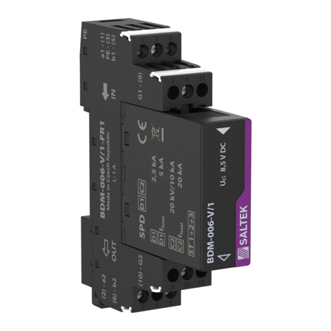
SALTEK BDM-006-V/1-FR1 installation instructions

