E.T. Systems Drive 500 User manual

ET DRIVE 500/600 USER 2016.001.001
End User Instruc ons
500kg Slide Gate Operators
Low Traffi c High Traffi c
www.et.co.za
NiceET
Designed, manufactured and
supported by ET NICE (Pty) Ltd

2
Introduc on.
Page 3 Be Safe! Instruc ons, warnings and obliga ons.
Page 4 Technical specifi ca ons.
Page 5 How to use the manual override.
Opera ng mode defi ni ons and examples.
Page 6 Collision sensing and safety overload rou nes.
Page 7 Safety infra-red beams func on. All modes except P.I.R.A.C. auto-close mode.
Page 8 “BT” Bu on triggers - Standard mode.
Page 9 “BT” Bu on triggers - Simple auto-close mode.
Page 10 “BT” Bu on triggers - Condominium auto-close mode.
Page 11 “BT” Bu on triggers - P.I.R.A.C. auto-close mode.
Page 12 “PED” Pedestrian trigger.With no safetybeams installed.
Page 13 “PED” Pedestrian trigger.With safety beams installed.
Page 14 “Loop” trigger.
Page 15 Auxiliary relay modes - Strike lock mode.
Page 16 Auxiliary relay modes - Magne c lock mode.
Page 17 Auxiliary relay modes - Courtesy light mode.
Page 18 Auxiliary relay modes - Receiver relay mode.
Page 19 Posi ve close mode.
Page 20 Holiday lock-out mode.
Page 21 Auto-close override/party mode.
Page 22 Tamper alarms.
Troubleshoo ng.
Page 23 Status LED indica ons and buzzer guide.
Page 24 Warranty.
For any assistance with this product,which is notcovered in this manual, please contact your service provider/installer.
Contact details of service provider/installer:
Company name:
Technician:
Contact number:
Email address:
Date of installa on:
Company stamp:

3
Be Safe!
WARNING!! These are the general safety obliga ons for the installers and users of ET Systems
automa on equipment.
1. Only suitably qualifi ed persons, may install, repair or service the product. Unless expressly indicated in the user instruc ons, no
user serviceable components can be found inside any ET Systems automa on product.
2. It is important for personal safety to study and follow all the instruc ons carefully. Incorrect installa on or misuse may cause
serious personal harm.
3. Keep the instruc ons in a safe place for future reference.
4. This product was designed and manufactured, strictly for the use indicated in the accompanying documenta on. Any other use
not expressly indicated in the documenta on, may damage the product and/or be a source of danger. ET NICE (Pty) Ltd cannot
accept responsibility for improper use or incorrect installa on of this product.
5. ET NICE (Pty) Ltd cannot accept responsibility if the principles of good workmanship are disregarded by the installer.
6. ET NICE (Pty) Ltd cannot accept responsibility regarding safety and correct opera on of the automa on, if other manufacturers’
equipment is added to this product.
7. Do not make any modifi ca ons or altera ons to this product. Do not subs tute any component of this product with any other
component not expressly designed into this product.
8. Anything other than expressly provided for in the accompanying instruc ons is not permi ed.
Prior to installa on:
1. All unnecessary ropes, chains and fasteners must be removed and all unnecessarylatches or locks must be disabled from locking.
2. The gate or door must be balanced correctly where it, neither opens nor closes from any posi on under its own load. When
operated by hand the gate or door should be free of hindrance and easily moved (In the case of a garage door if the balancing
springs need to be adjusted the adjustment should only be carried out by a qualifi ed and experienced person).
3. The construc on of the gate or door must be sound and automatable. It is the responsibility of the installer to ensure that the
mechanical components of the gate or door system are suffi cient to withstand the necessary forces in cases of overload.
4. It is the responsibility of the installer to ensure the gate or door is suffi ciently trapped within its range of travel by means of
mechanical ends of travel stoppers.
5. Ensure all fi xed moun ng points, such as the wall above the door in a garage door system or the posts in a swing gate system, are
sound and strong enough to allow proper fi xing of the operator.
6. It is the responsibility of the installer to ensure the installed posi on selected for this product, falls within the limita ons of the
products ingress protec on ra ng.
7. Ensure the area of installa on is not subject to explosive hazards. There should be no vola le gasses or fumes as these can present
a serious safety hazard.
8. All ET Systems garage door operators are supplied with a sealed 15A safety plug on lead for use in an electrical code of prac ce
approved plug point. Do not extend, modify or replace the plug lead unless duly qualifi ed as an electrician. Before installing the
unit, ensure the mains supply is switched off .
9. ET Systems gate operators are supplied with a terminal connec on for the electrical supply beneath the screwed down cover of
the operator. In the case of a model requiring 220Vac supply at the operator, an all pole nega vely biased switch, with a contact
opening of greater than 3mm must be installed within 1,5m of the operator. This switch must be clear of all workings ofthe system
and must be in a posi on secure from public access. This switch and its connec ons must be inspected and passed by a cer fi ed
electrician prior to using it.
10. It is the responsibility of the installer to ascertain that the designated persons (including children) intended to use the system,
do not suff er reduced physical sensory or mental capabili es, or lack of experience and knowledge, unless they have been given
supervision or instruc on concerning the use of the system by a person responsible for their safety.
11. The drive may not be installed on a door incorpora ng a wicket door, unless the drive is disabled by the release of the wicket door.
(Wicket door :- A pedestrian door within the main gate or door)
1. Ensure the working area is clear of obstruc ons and obstacles.
2. Install the safety warning s cker within clear view of where the gate or door will be operated from. Typically this would be
adjacent to any fi xed trigger switches or on the gate or door itself.
3. The emergency manual release must be installed where it is no higher than 1.8m from the fl oor level. This would apply to the cord
in a garage installa on or the lockable lever in a gate installa on.
4. Any addi onal fi xed door control switches such as wall consoles or keypads, if installed, must be at a height of at least 1.5m, within
clear sightof the gate or doorand away from any moving components ofthe system.
During installa on:
Con nued overleaf.......

4
5. It is highly recommended that a set of safety infra-red beams be used in conjunc on with this product. The safety beams must be
installed in such a way that the product isprevented from running when anything is in the path of the door or gate.
6. Over and above the recommenda on to use safety infra-red beams with this product it is mandatory to install and use a safety
beam set when using the automa c closing feature. It is recommended that a warning light be fi ed to any automa on system.
7. The emergency manual release instruc on label must be installed on or adjacent to the emergency manual release mechanism.
A er installa on - It is the responsibility of the installer to ensure the users:
1. Is profi cient in the use of the manual emergency release mechanism.
2. Is issued with the documenta on accompanying this product.
3. Understands thatthe gate or door may not be operated out of clear sight.
4. Ensures that children are kept clear of the gate or door area at all mes, and that children do not play with the remote transmi ers
or any fi xed trigger switches linked to the system.
5. Is instructed not to a empt to repair or adjust the automa on system and to be aware of the danger of con nuing to use the
automa on system in an unsafe condi on before a service provider a ends to it.
6. Is profi cient in tes ng the unit’s safety obstruc on sensing system.
7. Is aware of what to check for with regards to wear and tear that may need to be a ended to from me to me by the service
provider.
8. Is aware that a fa gued ba ery may not be disposed of in the general refuse and must be handed in at a ba ery merchant for safe
disposal. Before removing the ba ery from the system the household mains must be disconnected. In the case of the motor unit
being removed and scrapped, the ba ery must be removed fi rst.
Technical specifi ca ons.
TECHNICAL SPECIFICATIONS
Technical Data Drive 500 Drive 600
Rated gate mass. 500kg 500kg
Maximum gate travel. 99m 99m
Primary power supply to gate. 16Vac @ 1A 50Hz – 60Hz 220 – 240Vac @ 50Hz – 60Hz
Peak power consump on at gate. 26W 240W
Electrical class. Class 3 Class 1
Motor voltage. 12Vdc 12Vdc
Motorcurrent. Current limited to 25A. Current limited to 25A.
Duty cycle maximum.
See determining your duty cycle on page 7. 25% with 220Vac present 98% with 220Vac present
Number of opera ons on ba ery reserve.
(Ba ery health and charge level at me of
power failuredependent. Calculated on a5m
gate with rolling resistance of<10kgf)
100 using the standard 7Ah ba ery within
24hrs. 100 using the standard 7Ah ba ery within
24hrs.
Gate speed.
(Gate load and power supply dependent) Up to 28m/min. Up to 30m/min.
Rated Load. 300N 300N
Opera ng temperature range. -10 to 50° C (14F to 122F) -10 to 50° C (14F to 122F)
An -crushing safety sensing. Yes – Electronic gate profi ling Yes – Electronic gate profi ling
Auxiliary supply output. 12Vdc @ 500mA 12Vdc @ 500mA
Built in ba ery charger. Mul ple stage auto-calibra ng 1A Mul ple stage auto-calibra ng 1A
Receiver format. ET BLU MIX © backward compa ble with ET
BLUE (Rolling code) ET BLU MIX © backward compa ble with ET
BLUE (Rolling code)
Receiver frequency. 433.92MHz 433.92MHz
Receiver channels. 4CH (BT, PED, Aux relay, Holiday lock-out) 4CH (BT, PED, Aux relay, Holiday lock-out)
Receiver memory capacity. 1023 users 1023 users
All users can be allowed control of all channels. Yes Yes
Ingress protec on IPX4 IPX4
Physical dimensions See next page. See next page.

5
How to use the manual override.
Move gate open and closed by hand.
To disengage the gearbox (Manual mode)
1. Raise lock cover.
2. Insert the key.
3. Turn the key clockwise.
To disengage the gearbox (Manual mode)
4. Swing the manual override lever 90o
to the gearbox.
(Manual mode)
5. Manoeuvre the gate by hand.
To re-engage the gearbox (Normal mode)
6. Swing the manual override lever
back into it recess in the gearbox.
To re-engage the gearbox (Normal mode)
7. Turn the key counter clockwise.
8. Remove the key.
9. Lower the lock cover.
To re-engage the gearbox (Normal mode)
10. Ensure the gearing is engage by
pushing or pulling the gate un l the
gearing “clicks” in.

6
Basic opera ng features. Collision sensing and safety overload rou nes.
In the case of the gate colliding with an obstruc on such as a person passing through the entrance way, the collision sensing will automa cally detect
the collision and the system will run a safety overload rou ne.
Safety overload rou ne while gate is opening.
Ac on Response
Gate collides with a
pedestrian for example. Gate stops
opening.
Once gate has stopped.
Gate reverses
momentarily
to release
pressure.
No buzzer tones.
A er reversing
momentarily.
Gate stops and
waits for next
trigger to close. No buzzer tones.
Safety overload rou ne while gate is closing.
Ac on Response
Gate collides with a
pedestrian for example. Gate stops
closing.
Once gate has stopped. Gate reverses
back to the full
open posi on.
No buzzer tone.
A er reversing to the
full open posi on.
Gate remains
in the full open
posi on un l
the next trigger
to close.
No buzzer tone.

7
Safety infra-red beams func on.
All modes except P.I.R.A.C. Basic opera ng
features
If the safety beam input has been switched on, the control card will constantly monitor to ensure a set of safety beams is installed.
NB! If the BT input mode has been set to either simple auto-close or condominium mode, the safety beam input is required.
Below is an example of how the gates will behave whenever the safety beam input is ac vated.
Ac on Response
Momentary BT trigger. Gate begins
opening. No buzzer tones.
Safety beam input
triggered while gate is
opening.
Gate con nues
opening. No buzzer tones.
At full open posi on.
Safety beam input s ll
triggered.
Gate stops and
waits for next
trigger to close. No buzzer tones.
Momentary BT trigger.
Trigger is
ignored and
gate remains
open.
No buzzer tones.
Safety beam input
cleared.
Gate remains
in the full open
posi on un l
the next trigger
to close.
No buzzer tone.
Momentary BT trigger. Gate begins
closing. No buzzer tone.
Safety beam input while
the gate is closing. Gate stops and
reverses open. No buzzer tone.
At the full open
posi on.
Gate stops and
waits for next
trigger to close. No buzzer tone.
Momentary BT trigger. Gate begins
closing. No buzzer tone.
Gate closed.

8
Basic opera ng
features “BT” Bu on triggers.
Standard mode.
The BT func ons are the primary full gate opening func ons for motor vehicle access.
There are two ways of ac va ng the “BT” func ons on this control card. Either via the hardwired BT input or the BT receiver channel.
In Standard mode the gates respond to each BT trigger.
In Standard mode you have access to the following advanced features: - Holiday lock-out and Party mode.
Ac on Response
Momentary BT trigger. Gate begins
opening. No buzzer tones.
At full open posi on. Gate stops. No buzzer tones.
Momentary BT trigger. Gate begins
closing. No buzzer tones.
Momentary BT trigger.
Gate stops and
immediately
starts opening
again.
No buzzer tones.
Momentary BT trigger. Gate stops. No buzzer tones.
Momentary BT trigger. Gate begins
closing. No buzzer tones.
At full closed posi on. Gate stops. No buzzer tones.
Gate closed.

9
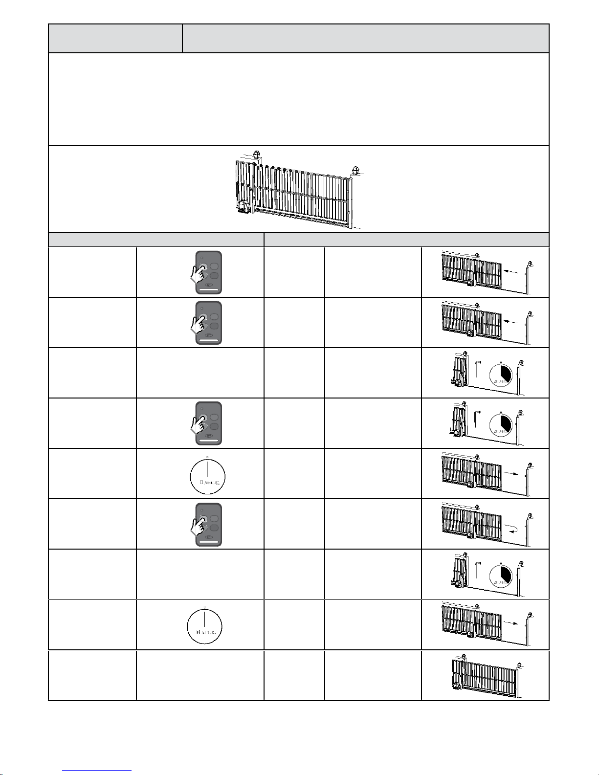
“BT” Bu on triggers.
Simple auto-close mode. Basic opera ng
features
The BT func ons are the primary full gate opening func ons for motor vehicle access.
There are two ways of ac va ng the “BT” func ons on this control card. Either via the hardwired BT input or the BT receiver channel.
Simple auto-close mode func ons exactly the same as standard mode except that the gates will close automa cally a er the programmed BT au-
to-close mer has med out.
In this mode you have access to the following advanced features: - Holiday lock-out and Party mode.
NB! For any auto-close feature to work, a pair of safety infra-red beams must be installed and func oning correctly. If no safety infra-red beams are
installed then the gates will open but notclose again.
Ac on Response
Momentary BT trigger. Gate begins
opening. No buzzer tones.
At full open posi on. Gate stops. No buzzer tones.
Momentary BT trigger
or auto-close mer
meout. Safety beam
input not triggered.
Gate begins
closing. No buzzer tones.
Momentary BT trigger.
Gate stops and
immediately
starts opening
again.
No buzzer tones.
Momentary BT trigger. Gate stops. No buzzer tones.
Momentary BT trigger
or auto-close mer
meout. Safety beam
input not triggered.
Gate begins
closing. No buzzer tones.
At full closed posi on. Gate stops. No buzzer tones.
Gate closed.
10
Basic opera ng
features “BT” Bu on triggers.
Condominium auto-close mode.
The BT func ons are the primary full gate opening func ons for motor vehicle access.
There are two ways of ac va ng the “BT” func ons on this control card. Either via the hardwired BT input or the BT receiver channel.
In Condominium auto-close mode, all BT triggers are treated as open, keep opening, keep open or re-open triggers. The gates will only close once the
BT auto-close mer has med out.
In Condominium auto-close mode the following advanced features are NOT available: - Holiday lock-out and Party mode.
NB! For any auto-close feature to work, a pair of safety infra-red beams must be installed and func oning correctly. If no safety infra-red beams are
installed then the gates will open but notclose again.
Ac on Response
Momentary BT trigger. Gate begins
opening. No buzzer tones.
Momentary BT trigger
while gate is opening.
The trigger is
ignored and the
gate con nues
opening.
No buzzer tone.
At full open posi on.
Gate stops
andauto-close
mer starts
coun ng down.
No buzzer tones.
Momentary BT trigger.
Gate remains
open and auto-
close mer
resets.
No buzzer tones.
Auto-close mer
meout. Safety beam
input not triggered.
Gate begins
closing. No buzzer tones.
Momentary BT trigger.
Gate stops and
immediately
starts opening
again.
No buzzer tones.
At full open posi on.
Gate stops
andauto-close
mer starts
coun ng down.
No buzzer tones.
Auto-close mer
meout. Safety beam
input not triggered.
Gate begins
closing. No buzzer tones.
At full closed posi on. Gate stops. No buzzer tones.
Gate closed.

11
“BT” Bu on triggers.
P.I.R.A.C. auto-close mode. Basic opera ng
features
The BT func ons are the primary full gate opening func ons for motor vehicle access.
There are two ways of ac va ng the “BT” func ons on this control card. Either via the hardwired BT input or the BT receiver channel.
In P.I.R.A.C. auto-close mode, all BT triggers are treated as per simple auto-close. The diff erence in this mode is how the system responds to the safety
beam triggers while the gate is opening. Below is an example of P.I.R.A.C. auto-close mode when the safety beam circuit is triggered while the gate
is in opera on.
In this mode mode the following advanced features are available: - Holiday lock-out and Party mode.
NB! For any auto-close feature to work, a pair of safety infra-red beams must be installed and func oning correctly. If no safety infra-red beams are
installed then the gates will open but notclose again.
Ac on Response
Momentary BT trigger. Gate begins
opening. No buzzer tones.
Safety beam circuit
triggered while gate is
opening.
The gate
con nues
opening. No buzzer tone.
Safety beam circuit
cleared while gate is
opening.
Gate stops and
immediately
starts closing
again.
No buzzer tones.
Safety beam circuit
triggered while gate is
closing.
Gate stops and
immediately
starts opening
again.
No buzzer tones.
Gate reaches open
posi on while safety
beam circuit is s ll
triggered.
Gate remains
open wai ng
for safety beam
circuit to be
cleared.
No buzzer tones.
Safety beam circuit
cleared while gate is in
the open posi on.
Auto-close
mer starts
coun ng down.
No buzzer tones.
Auto-close mer mes
out.Safety beam circuit
not triggered.
Gate begins
closing. No buzzer tones.
At full closed posi on. Gate stops. No buzzer tones.
Gate closed.

12
Basic opera ng
features “PED” Pedestrian trigger.
(With no safety beams installed)
The PED trigger is a higher security op on and is used when access to or from the property is limited to exclude motor vehicles.
In the case of no safety beams being installed then the pedestrian auto-close func onality is disallowed for safety.
If the Loop or the BT triggers are ac vated at any me during the pedestrian rou ne, the gate will open to the full open posi on and the pedestrian
transac on is cancelled. The system then reverts to either the Loop or BT trigger mode depending on which was triggered.
There are two ways of ac va ng the “PED” func ons on this control card. Either via the hardwired PED input or the PED receiver channel.
Ac on Response
Momentary PED trigger.
Buzzer beeps
pre-run
warning.
A er buzzer silences. Gate begins
opening. No buzzer tones.
Atpreviously
programmed
pedestrian opening
distance.
Gate stops
and waits for
a pedestrian
trigger to close.
No buzzer tones.
Momentary PED trigger. Buzzer beeps
pre-run
warning.
A er buzzer silences. Gate begins
closing. No buzzer tones.
At full closed posi on. Gate stops. No buzzer tones.
Gate closed.

13
“PED” Pedestrian trigger.
(With safety beams installed) Basic opera ng
features
The PED trigger is a higher security op on and is used when access to or from the property is limited to exclude motor vehicles.
If the safety beams are triggered while the gate is closing in pedestrian mode, the gate will only return to the preprogrammed pedestrian open
posi on.
If the Loop or the BT triggers are ac vated at any me during the pedestrian rou ne, the gate will open to the full open posi on and the pedestrian
transac on is cancelled. The system then reverts to either the Loop or BT trigger mode depending on which was triggered.
There are two ways of ac va ng the “PED” func ons on this control card. Either via the hardwired PED input or the PED receiver channel.
Ac on Response
Momentary PED trigger.
Buzzer beeps
pre-run
warning.
A er buzzer silences. Gate begins
opening. No buzzer tones.
Atpreviously
programmed
pedestrian opening
distance.
Gate stops and
the pedestrian
auto-close
mer starts
coun ng down.
No buzzer tones.
Momentary PED trigger
or safety beam circuit
trigger.
Pedestrian
auto-close
mer resets.
No buzzer tones.
Pedestrian auto-close
mer mes out.
Buzzer beeps
pre-run
warning.
A er buzzer silences. Gate begins
closing. No buzzer tones.
At full closed posi on. Gate stops. No buzzer tones.
Gate closed.

14
Basic opera ng
features “Loop” trigger.
The Loop trigger mode is exactly the same as Condominium auto-close mode.
The only way to trigger loop detector mode is via the hardwired LPT input.
In Loop detector mode, a LPT trigger is treated as open, and any BT or LPT trigger is treated as a keep opening, keep open triggers or re-opentrigger
while the gates are running. The gates will only close once the auto-close mer has med out. The loop mode transac on will only clear once the
gates reach the closed posi on again.
NB! For any auto-close feature to work, a pair of safety infra-red beams must be installed and func oning correctly. If no safety infra-red beams are
installed then the gates will open but notclose again.
Ac on Response
Loop trigger. Gate begins
opening. No buzzer tones.
Momentary BT trigger
or Loop trigger while
gate is opening.
The trigger is
ignored and the
gate con nues
opening.
No buzzer tone.
At full open posi on.
Gate stops
andauto-close
mer starts
coun ng down.
No buzzer tones.
Momentary BT trigger
or Loop trigger while
gate is open.
Gate remains
open and auto-
close mer
resets.
No buzzer tones.
Auto-close mer
meout. Safety beam
input not triggered.
Gate begins
closing. No buzzer tones.
Momentary BT trigger
or Loop trigger while
gate is closing.
Gate stops and
immediately
starts opening
again.
No buzzer tones.
At full open posi on.
Gate stops
andauto-close
mer starts
coun ng down.
No buzzer tones.
Auto-close mer
meout. Safety beam
input not triggered.
Gate begins
closing. No buzzer tones.
At full closed posi on. Gate stops. No buzzer tones.
Gate closed.

15
Auxiliary relay modes.
Strike lock mode. Basic opera ng
features
With Strike lock mode selected, the auxiliary relay will pulse for the preprogrammed on me, half a second before the gate opens.
Whenever a lock is installed with the system, a separate ba ery backed up power supply matching the lock load must be installed. Failure to do this
can damage the charger and ba ery of the control unit.
Below is an example of strike lock mode when standard BT mode is ac ve.
Ac on Response
Momentary BT trigger. Auxiliary relay
ac vates. No buzzer tone.
Half a second a er
the auxiliary relay has
ac vated.
Gate begins
opening. No buzzer tone.
A er the
preprogrammed relay
on me.
Auxiliary relay
deac vates and
gate con nues
opening.
No buzzer tone.
Gate reaches open
posi on. Gate stops. No buzzer tone.
Momentary BT trigger. Gate begins
closing. No buzzer tone.
At full closed posi on. Gate stops. No buzzer tone.
Gate closed.

16
Basic opera ng
features Auxiliary relay modes.
Magne c lock mode.
With Magne c lock mode selected, the auxiliary relay will ac vate, half a second before the gate opens and remain ac vive un l half a second a er
the gate has closed again.
Whenever a lock is installed with the system, a separate ba ery backed up power supply matching the lock load must be installed. Failure to do this
can damage the charger and ba ery of the control unit.
Below is an example of magne c lock mode when standard BT mode is ac ve.
Ac on Response
Momentary BT trigger. Auxiliary relay
ac vates. No buzzer tone.
Half a second a er
the auxiliary relay has
ac vated.
Gate begins
opening. No buzzer tone.
Gate reaches open
posi on. Gate stops. No buzzer tone.
Momentary BT trigger. Gate begins
closing. No buzzer tone.
At full closed posi on. Gate stops. No buzzer tone.
Half a second a er gate
has reached the full
closed posi on.
Auxiliary relay
deac vates. No buzzer tone.
Gate closed.

17
Auxiliary relay modes.
Courtesy light mode. Basic opera ng
features
With courtesy light mode selected, the auxiliary light will switch on as the gate begins opening and remain on for the programmed light on me a er
the gate has closed.
The auxiliary relay can also be triggered to switch on without the gate opening by simply pressing and releasing any remote bu on programmed into
the auxiliary relay func on of the receiver.
The relay on me for the two diff erent triggers can be programmed to diff erent on mes if wanted.
Below is an example of courtesy light mode when standard BT mode is ac ve.
Ac on Response
Momentary BT trigger.
Auxiliary relay
ac vates.
No buzzer tone.
Gate begins
opening.
Gate reaches open
posi on. Gate stops. No buzzer tone.
Momentary BT trigger. Gate begins
closing. No buzzer tone.
At full closed posi on.
Gate stops.
No buzzer tone.
Relay on mer
begins coun ng
down.
A er relay on mer
meout.
Auxiliary relay
deac vates. No buzzer tone.
If the gate is closed and any remote bu on programmed into the auxiliary relay func on is pressed momentarily,
the following will occur.
Auxiliary relay status Ac on Response
Momentary
auxiliary relay
trigger.
Auxiliary relay
switches on for
programmed
me.
No buzzer tone.
Momentary
auxiliary relay
trigger.
Auxiliary relay
switches off . No buzzer tone.
Gate closed.

18
Basic opera ng
features Auxiliary relay modes.
Receiver relay mode.
With receiver relay mode selected, the auxiliary relay will operate in exactly the same way as a single channel receiver would, whenever a transmi er
bu on programmed into the “Relay” receiver func on is pressed and released.
Latch mode.
The transmi er must be released and pressed again to reac vate the relay each me.
Ac on Response
Momentary relay trigger. Auxiliary relay
switches on. No buzzer tones.
Momentary relay trigger. Auxiliary relay
switches off . No buzzer tones.
One shot pulse mode.
The transmi er must be released and pressed again to reac vate the relay each me.
Ac on Response
Momentary relay trigger. Auxiliary relay
switches on. No buzzer tones.
Relay mer mes out. Auxiliary relay
switches off . No buzzer tones.

19
Posi ve close mode. Advanced features
With posi ve close mode ac vated, the gate will surge onto the closed stopper a er seeing the closed limit.
This feature is useful when installing an electric lock or when trying to ensure an electric fencing gate contact always closes when the gate is in the
closed posi on.
Ac on Response
Momentary BT trigger. Gate begins
opening. No buzzer tones.
At full open posi on. Gate stops. No buzzer tones.
Momentary BT trigger. Gate begins
closing. No buzzer tones.
Momentary BT trigger. Gate stops. No buzzer tones.
Momentary BT trigger. Gate begins
opening. No buzzer tones.
Momentary BT trigger. Gate stops. No buzzer tones.
Momentary BT trigger. Gate begins
closing. No buzzer tones.
At full closed posi on. Gate stops. No buzzer tones.
When gate has stopped
on the closed limit.
Gate physically
surges onto
the mechanical
closed stopper.
No buzzer tone.
Gate closed.

20
Advanced features Holiday lock-out mode.
This feature is useful at mes when access to the property needs to be disallowed to secondary level key holders, such as housekeepers or the garden
service company, for extended periods of me. An example of when the holiday lock-out func on would be useful is when the home owner is away
on holiday. With holiday lock-out mode ac ve, any trigger on any input will simply result in the control card beeping to indicate the gates are being
kept locked inten onally. As soon as the holiday lock-out mode is deac vated, the system will resume normal opera on.
Holiday lock-out will only work in the closed posi on.
Holiday lock-outis not available in condominium mode.
Ac on Response
Momentary trigger
from any transmi er
bu on programmed
into holiday lock-out
func on.
Buzzer begins toning and
status LED comes on.
BT bu on while buzzer
is sounding to confi rm
that you want to
ac vate holiday lock-
out.
If no BT bu on is
pressed during this 5
second window, the
holiday lock-out status
will not change.
Buzzer and status LED beep/
fl ash rapidly.
Any BT, Loop or PED
triggers. Gate does not open.
Buzzer, status LED.
Momentary trigger
from any transmi er
bu on programmed
into holiday lock-out
func on.
Buzzer begins toning and
status LED comes on.
BT bu on while
buzzer is sounding to
confi rm that you want
to deac vate holiday
lock-out.
If no BT bu on is
pressed during this 5
second window, the
holiday lock-out status
will not change.
Buzzer beeps, status LED
reverts to gate running
indica on and gate begins
opening.
Normal opera on is now func onal.
Gate must be closed
to start.
Other manuals for Drive 500
1
This manual suits for next models
1
Table of contents
Other E.T. Systems Gate Opener manuals


Popular Gate Opener manuals by other brands


Wallace Perimeter Security
Wallace Perimeter Security Kinetic 1 Installation and maintenance manual

Aprimatic
Aprimatic AP424 Mechanical installation, Use and Maintenance instructions

CAME
CAME BX Series manual

RAMSET
RAMSET RAM-30 UL instruction manual

CAME
CAME 8K06SL-007 manual

Motorline professional
Motorline professional PERSA 400 User's and installer's manual


