operating the controls. Controls intended to be used to reset a Vehicular Gate Operator after 2 sequential activations
of the entrapment protection device or devices must be located in the line-of-sight of the gate. Outdoor or easily
accessible controls shall have a security feature to prevent unauthorized use.
f) All warning signs and placards must be installed where visible in the area of the gate.
g) For Vehicular Gate Operators utilizing a non-contact sensor in accordance with 30A.1.1 Type B1 non-contact sensor
(photo electric sensor or the equivalent)
1) See instructions on the placement of non-contact sensors for each Type of application,
2) Care shall be exercised to reduce the risk of nuisance tripping, such as when a vehicle, trips the sensor while
the gate is still moving, and
3) One or more non-contact sensors shall be located where the risk of entrapment or obstruction exists, such as
the perimeter reachable by a moving gate or barrier.
h) For a Vehicular Gate Operator utilizing a contact sensor in accordance with 30A.1.1
1) One or more contact sensors shall be located at the leading edge, trailing edge, and postmounted both inside
and outside of a vehicular horizontal slide gate.
2) One or more contact sensors shall be located at the bottom edge of a vehicular vertical lift gate.
3) One or more contact sensors shall be located at the pinch point of a vehicular vertical pivot gate.
4) A hardwired contact sensor shall be located and its wiring arranged so that the communication between the sen-
sor and the vehicular gate operator is not subjected to mechanical damage.
5) A wireless contact sensor such as one that transmits radio frequency (RF) signals to the vehicular gate operator
for entrapment protection functions shall be located where the transmission of the signals are not obstructed or
impeded by building structures, natural landscaping or similar obstruction. A wireless contact sensor shall func-
tion under the intended end-use conditions.
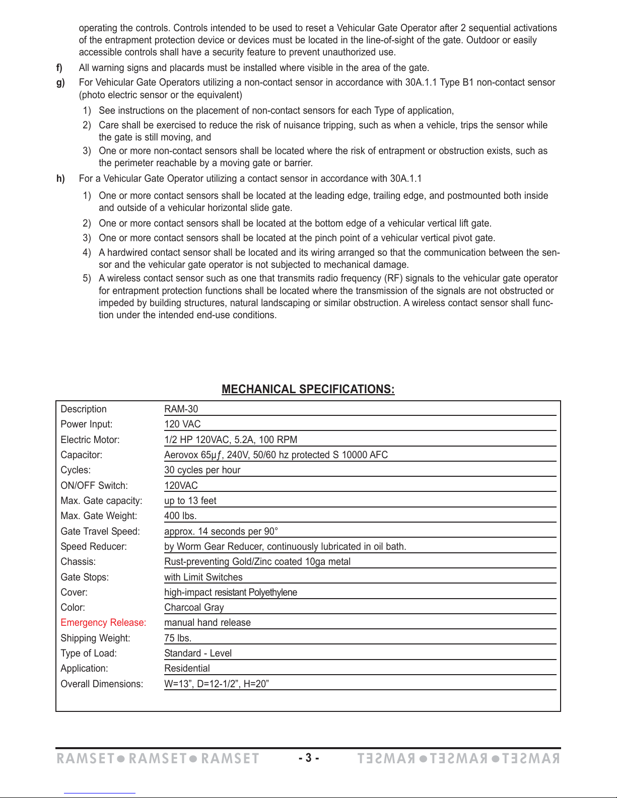
MECHANICAL SPECIFICATIONS:
Description RAM-30
Power Input: 120 VAC
Electric Motor: 1/2 HP 120VAC, 5.2A, 100 RPM
Capacitor: Aerovox 65µƒ, 240V, 50/60 hz protected S 10000 AFC
Cycles: 30 cycles per hour
ON/OFF Switch: 120VAC
Max. Gate capacity: up to 13 feet
Max. Gate Weight: 400 lbs.
Gate Travel Speed: approx. 14 seconds per 90°
Speed Reducer: by Worm Gear Reducer, continuously lubricated in oil bath.
Chassis: Rust-preventing Gold/Zinc coated 10ga metal
Gate Stops: with Limit Switches
Cover: high-impact resistant Polyethylene
Color: Charcoal Gray
Emergency Release: manual hand release
Shipping Weight: 75 lbs.
Type of Load: Standard - Level
Application: Residential
Overall Dimensions: W=13”, D=12-1/2”, H=20”
RAMSET
z
RAMSET
z
RAMSET
RAMSET
z
RAMSET
z
RAMSET
- 3 -