E.T. Systems Drive 300 User manual

ET DRIVE300 INSTALLER 2016.001.001
Installer Instrucons
Low trac 300kg Slide Gate Operator
www.et.co.za
300

2
Introducon.
Page 3 Be Safe! Instrucons, warnings and obligaons.
Page 4 Technical specicaons.
Page 5 Component idencaon and operator dimensions.
Site preparaon.
Page 6 Gate preparaon and mechanical requirements.
Page 7 Duty cycle.
Page 7 Motor posioning.
Page 8 Cabling requirements.
Hardware installaon - Mechanical.
Page 9 Baseplate kit and installing the baseplate.
Page 10 Cable conduit height above baseplate.
Page 10 How to use the manual release override.
Page 11 Mounng the motor onto the baseplate.
Page 12 Installing the rack.
Hardware installaon - Electrical.
Page 14 Terminang the AC supply.
Page 15 Wiring and terminaon of the control card.
Page 16 Installing the limit actuator.
Control card programming and setup.
Page 17 Using the control card display and dashboard.
Page 18 Programming menu quick reference guide.
Page 19 Seng up the gate runme.
Page 20 Selecng a safety level.
Page 20 Safety infra-red beams setup.
Page 21 Selecng a BT operang mode and adjusng the BT auto-close me.
Page 22 Seng up the pedestrian open distance and pedestrian auto-close me.
Page 23 Receiver programming and setup.
Page 29 Switching the AC monitoring and/or built-in charger on or o.
Page 30 Adjusng the length of the slow speed at the ends of travel.
Page 30 Switching the posive close mode on or o.
Page 31 Selecng the Auxiliary relay’s mode of operaon.
Operang mode denions and examples.
Page 32 Collision sensing and safety overload rounes
Page 33 Safety infra-red beams funcon. All modes except P.I.R.A.C. auto-close mode.
Page 34 “BT” Buon triggers - Standard mode.
Page 35 “BT” Buon triggers - Simple auto-close mode.
Page 36 “BT” Buon triggers - Condominium auto-close mode.
Page 37 “BT” Buon triggers - P.I.R.A.C. auto-close mode.
Page 38 “PED” Pedestrian trigger. With no safety beams installed.
Page 39 “PED” Pedestrian trigger. With safety beams installed.
Page 40 Auxiliary relay modes - Strike lock mode.
Page 41 Auxiliary relay modes - Magnec lock mode.
Page 42 Auxiliary relay modes - Receiver relay mode.
Page 43 Auxiliary relay modes - Courtesy light mode.
Page 44 Auxiliary relay modes - Alarm mode.
Page 45 Posive close mode.
Page 46 Holiday lock-out mode.
Page 47 Auto-close override/party mode.
Troubleshoong.
Page 48 Status LED, buzzer and diagnoscs menu denions.
Page 49 Troubleshoong guide and display denions.
Page 50 Warranty.

3
Be Safe!
WARNING!! These are the general safety obligaons for the installers and users of ET Systems
automaon equipment. A copy of this document also appears in the user instrucons. Those
instrucons must be issued to the responsible end user during the handover and instrucon
meeng.
1. Only suitably qualied persons, may install, repair or service the product. Unless expressly indicated in the user instrucons, no
user serviceable components can be found inside any ET Systems automaon product.
2. It is important for personal safety to study and follow all the instrucons carefully. Incorrect installaon or misuse may cause
serious personal harm.
3. Keep the instrucons in a safe place for future reference.
4. This product was designed and manufactured, strictly for the use indicated in the accompanying documentaon. Any other use
not expressly indicated in the documentaon, may damage the product and/or be a source of danger. ET Systems cannot accept
responsibility for improper use or incorrect installaon of this product.
5. ET Systems cannot accept responsibility if the principles of good workmanship are disregarded by the installer.
6. ET Systems cannot accept responsibility regarding safety and correct operaon of the automaon, if other manufacturers’
equipment is added to this product.
7. Do not make any modicaons or alteraons to this product. Do not substute any component of this product with any other
component not expressly designed into this product.
8. Anything other than expressly provided for in the accompanying instrucons is not permied.
Prior to installaon:
1. All unnecessary ropes, chains and fasteners must be removed and all unnecessary latches or locks must be disabled from locking.
2. The gate or door must be balanced correctly where it, neither opens nor closes from any posion under its own load. When
operated by hand the gate or door should be free of hindrance and easily moved (In the case of a garage door if the balancing
springs need to be adjusted the adjustment should only be carried out by a qualied and experienced person).
3. The construcon of the gate or door must be sound and automatable. It is the responsibility of the installer to ensure that the
mechanical components of the gate or door system are sucient to withstand the necessary forces in cases of overload.
4. It is the responsibility of the installer to ensure the gate or door is suciently trapped within its range of travel by means of
mechanical ends of travel stoppers.
5. Ensure all xed mounng points, such as the wall above the door in a garage door system or the posts in a swing gate system, are
sound and strong enough to allow proper xing of the operator.
6. It is the responsibility of the installer to ensure the installed posion selected for this product, falls within the limitaons of the
products ingress protecon rang.
7. Ensure the area of installaon is not subject to explosive hazards. There should be no volale gasses or fumes as these can present
a serious safety hazard.
8. All ET Systems garage door operators are supplied with a sealed 15A safety plug on lead for use in an electrical code of pracce
approved plug point. Do not extend, modify or replace the plug lead unless duly qualied as an electrician. Before installing the
unit, ensure the mains supply is switched o.
9. ET Systems gate operators are supplied with a terminal connecon for the electrical supply beneath the screwed down cover of
the operator. In the case of a model requiring 220Vac supply at the operator, an all pole negavely biased switch, with a contact
opening of greater than 3mm must be installed within 1,5m of the operator. This switch must be clear of all workings of the system
and must be in a posion secure from public access. This switch and its connecons must be inspected and passed by a cered
electrician prior to using it.
10. It is the responsibility of the installer to ascertain that the designated persons (including children) intended to use the system,
do not suer reduced physical sensory or mental capabilies, or lack of experience and knowledge, unless they have been given
supervision or instrucon concerning the use of the system by a person responsible for their safety.
11. The drive may not be installed on a door incorporang a wicket door, unless the drive is disabled by the release of the wicket door.
(Wicket door :- A pedestrian door within the main gate or door)
1. Ensure the working area is clear of obstrucons and obstacles.
2. Install the safety warning scker within clear view of where the gate or door will be operated from. Typically this would be
adjacent to any xed trigger switches or on the gate or door itself.
3. The emergency manual release must be installed where it is no higher than 1,8m from the oor level. This would apply to the cord
in a garage installaon or the lockable lever in a gate installaon.
4. Any addional xed door control switches such as wall consoles or keypads, if installed, must be at a height of at least 1,5m, within
clear sight of the gate or door and away from any moving components of the system.
During installaon:
Connued overleaf.......

4
5. It is highly recommended that a set of safety infra-red beams be used in conjuncon with this product. The safety beams must be
installed in such a way that the product is prevented from running when anything is in the path of the door or gate.
6. Over and above the recommendaon to use safety infra-red beams with this product it is mandatory to install and use a safety
beam set when using the automac closing feature. It is recommended that a warning light be ed to any automaon system.
7. The emergency manual release instrucon label must be installed on or adjacent to the emergency manual release mechanism.
Aer installaon - It is the responsibility of the installer to ensure the users:
1. Is procient in the use of the manual emergency release mechanism.
2. Is issued with the documentaon accompanying this product.
3. Understands that the gate or door may not be operated out of clear sight.
4. Ensures that children are kept clear of the gate or door area at all mes, and that children do not play with the remote transmiers
or any xed trigger switches linked to the system.
5. Is instructed not to aempt to repair or adjust the automaon system and to be aware of the danger of connuing to use the
automaon system in an unsafe condion before a service provider aends to it.
6. Is procient in tesng the unit’s safety obstrucon sensing system.
7. Is aware of what to check for with regards to wear and tear that may need to be aended to from me to me by the service
provider.
8. Is aware that a fagued baery may not be disposed of in the general refuse and must be handed in at a baery merchant for safe
disposal. Before removing the baery from the system the household mains must be disconnected. In the case of the motor unit
being removed and scrapped, the baery must be removed rst.
Technical specicaons.
Rated gate mass. 300kg
Maximum gate leaf length. 25m
Primary power supply to gate. 220 – 240Vac @ 50Hz – 60Hz
(A low voltage plug-in transformer can be purchased and installed if required)
Peak power consumpon at gate 18W
Electrical class. Class 1
Motor voltage. 24Vdc
Motor current liming. 5A Starng / 3,5A Running
Rated duty cycle. 25% with 220Vac present (See determining your duty cycle on page 7)
Number of operaons on baery reserve
within 24 hours of power failure. 100 (Gate load and baery health dependent. Based on a gate opening of 4m)
Gate speed. 25m/min (Gate load and baery health dependent)
Rated Load. 300N Starng / 240N Running
Operang temperature range. -10 to 50° C (14F to 122F)
An-crushing safety sensing. Yes – Electronic gate proling
Auxiliary supply output. 12Vdc @ 400mA
Built in baery charger. Mulple stage auto-calibrang (350mA peak)
Receiver format. ET BLU MIX ® Backward compable with ET BLUE (Rolling code)
Receiver frequency. 433.92MHz
Receiver channels. 4CH (BT, PED, Aux relay, Holiday lock-out)
Receiver memory capacity. 32 users
All users can be allowed control of all channels. Yes
Ingress protecon. IPX4

5
1
2
3
4
5
6
77
8
9
10
12
11
13
14
15
16
17
18
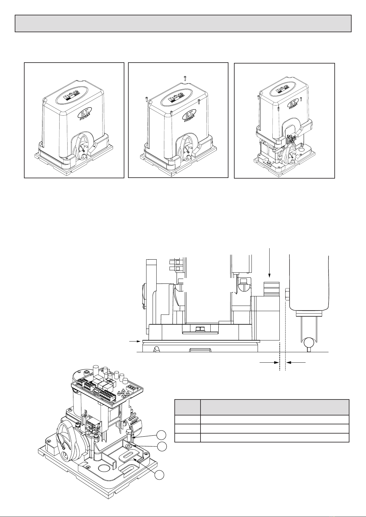
Component idencaon and descripons.
Diagram
number Descripon Diagram
number Descripon
1Control card 10 Baseplate
2Dashboard 11 220V connector
3Plug-in terminal connectors 12 Manual release
4Manual release monitoring reed switch 13 Manual release lock
5Baery 14 Electric motor
6Transformer housing 15 Electric motor brush ports
7Mounng bolts 16 Revoluon counter ring magnet
8Gearbox 17 Ends of travel limits, reed switch
9Cable inlets 18 Output drive pinion
260213
15
91
258
Operator dimensions.

6
BEFORE ATTEMPTING TO INSTALL A SLIDE GATE OPERATOR, PLEASE BE CERTAIN YOU HAVE READ AND
UNDERSTOOD THE FOLLOWING TO ENSURE CONTINUED SATISFACTORY SAFE SERVICE FROM THIS PRODUCT:
The following are points to note before installing your new slide gate operator:
1. Gate mechanics.
2. Duty cycle.
3. Where to posion the gate motor with regards to ingress protecon.
4. Cabling requirements.
Gate mechanics.
Gate Leaf:
Gate leaf must be sound and of sucient construcon to accommodate an operator of this type (see technical specicaons).
Gate leaf should be straight and true with minimal deviaon to the fascia that the rack must aach to (no ‘banana-eect’).
Wheels and track:
The track must be secure, straight, level and free of all obstrucons.
Recommended wheel type and size for this automaon is steel or steel alloy, machined or cast wheels of at least 100mm diameter using sealed roller
bearings. The larger the wheel the less rolling resistance generated. Larger wheels also maintain their plumb and momentum longer. When wheels
are xed in the gate, and not able to pivot, binding can occur if the gate is bowed. (Banana eect) For wheel prole and matching track types, see the
three examples below:
Recommended Less problemac Problemac
Guides:
• It is recommended that a roller guide consisng of a sealed roller bearing clad in nylon be used.
• The guidance system should be installed at the top edge of the gate whenever possible. In cases where this is not possible the guidance system
should never be below the halfway point of the total gate height when the gate is in posion on its track.
• In the case of a single guide roller running in a guide channel, ensure the guide never touches both inside walls of the channel simultaneously. This
causes the roller to snag as it tries to roll in both direcons at once.
• In the case of 2 guide rollers being used on either side of the gate leaf, ensure that both wheels never touch the leaf simultaneously.
• Avoid using more than 1 guide roller on the same side of the gate leaf to prevent binding.
• As with the wheels the larger the guide the less rolling resistance generated.
Gate Travel:
Using a sherman’s pull scale, as shown below, pull the gate fully open and fully closed at approximately the same speed as the operator you intend to
use (see technical specicaons). For opmum performance, ensure that the maximum resistance does not exceed 30kgF starng and 24kgF running.
The starng resistance should fall away within 300 to 500mm. Note the recommended track, wheel and guide types menoned b) and c) above.
NB! Install physical stoppers at the ends of the gate travel to prevent the gate over-running the ends of the track as shown here. (Naonal safety
standard requirement)
End of travel stopper!
End of travel stopper!
Gate preparaon and mechanical requirements.

7
Duty Cycle.
The Formula used to determine duty cycle is:
Run me x 100 = Duty cycle
Run me + rest me
Working example 1: (Low duty cycle)
Run me: 12 seconds.
Rest me: 36 seconds.
12 ÷ 48 x 100 = 25
Thus the duty cycle in example 1 is said to be 25%
Working example 2: (High duty cycle)
Run me: 12 seconds.
Rest me: 1 second.
12 ÷ 13 x 100 = 92.3
Thus the duty cycle in example 2 is said to be 92.3%
The above examples do not factor in resistance and gate mass. These two elements contribute greatly to the amount of heat generated in your gate
automaon system.
Below are the maximum allowed duty cycles based on the gate mass and rolling resistance for the ET motor models. These are calculated to conform
to the standards set out in the SANS 60335-95-1:2011 safety code.
Duty cycle capabilies guideline of the ET Drive series motor models:
Model Gate Mass Starng resistance Rolling resistance Max Duty Cycle
Drive 300 ≤ 300kg ≤ 30kgf ≤ 24 kgf 25%
Where to posion the gate motor.
Liquid ingress:
The ET Drive series motor models all carry an ingress protecon rang of IPX4. This means they are protected from splashing water. They are not
water ght as there are sensive electronic and electrical circuits that require uninhibited airow to remain cool and dry.
When deciding on an installaon posion, be aware of water collecon points around and near the desired mounng posion of the motor unit. If
the water does not ow away quickly enough, it can seep into the system and cause expensive and possibly hazardous damage. Always install the unit
higher than the highest level that any water owing past the motor unit can reach.
Physical protecon:
Whenever possible, always install the gate motor on the opposite side of the gate’s guide/emergency post, to the driveway itself. This way it is out of
the path of the motor vehicles as they pass through the entrance/exit.

8
Cabling requirements.
• Before mounng the operator ensure your cables and conduing are in place to prevent any inconvenience at a later stage.
• All household mains cabling and circuits need to be installed by a qualied electrician and signed o by a registered electrician.
• Allow for spare cabling in case of faulty cable & breakages (especially important when using low specicaon cable).
• As automaon systems vibrate when in use, it is highly recommended that only mul-stranded, exible cables be used.
• If installing an intercom, remember to allow for sucient cable cores for all the users of the system as per manufacturers cabling requirements.
• The Drive 300 motor is designed to facilitate 1 x 20mm conduit going directly into its housing from below. If more cabling needs to be routed to the
motor, we suggest that a weatherproof electrical box be installed as a distribuon box. All of the circuits can then be extended to the distribuon
box and terminated there.
1
29V
3
Alarm
panel
2
11 4
10
8
9
1
6
5
7
1. Courtesy lights twin + earth 1.0mm back to motor housing and
isolator switch.
7. Free exit loop 1.5mm silicone insulated single core exible stranded
cable back to loop detector that is typically installed in the motor
housing.
2. Intercom gate staon (check with intercom supplier for cable
specicaons)
8. From intercom internal equipment (check with intercom supplier
for specicaons) + 5 cores 0,5mm stranded for status LED, BT and
Pedestrian triggers.
3. (220Vac) - twin + earth: 2,5mm stranded (An all pole negavely
biased isolator must be installed within 1,5m of the motor unit, in
circuit with the 220Vac supply)
9. Alarm monitoring circuit. 2 cores 0,5mm stranded back to motor
housing.
4. Safety infra-red beam RX power & switch. 4 cores 0,5mm stranded
back to motor housing.
10. Oponal plug in transformer for low trac sites (29Vac) - twin +
earth. Min 0,5mm stranded (1Amp)
5. Safety infra-red beam TX power. 2 cores 0,5mm stranded back to
motor housing.
11. Lock power supply. Twin + earth 2,5mm stranded from isolator
switch.
6. Electric lock power. 2 cores 0,5mm stranded back to independent
lock power supply via motor housing.

9
Baseplate and fastener kit assembly.
1
1
1
1
2
5
1
1
3
3
4
3
2
2
Diagram
number Descripon
1M10 Machine nuts.
2M10 Flat washers.
3M10 J-Bolts for concrete casng method.
4Cabling conduit piping.
5Baseplate.
Installing the baseplate.
There are a number of dierent fastening techniques that can be used to fasten the baseplate in posion. The standard kit is supplied with J-bolts
so that the baseplate can be cast in concrete. While this method oers a nice solid base it takes more than 48hrs to install as the concrete must cure
properly before connuing with the installaon. Whichever mounng method you opt for, the posion of the base plate will always remain the same.
Below are the dimensions to use when posioning the baseplate. The baseplate should be installed above the highest point of ooding that may occur
with the run o of water down the driveway.
PLAN VIEW OF THE BASEPLATE INSTALLED
Proudest component of
the gate on the motor side
Edge of the baseplate
nearest to the gate
Required space
30 - 50mm
Gate positioned where the proudest component
is opposite the base plate of the operator.
Base plate positioned on the opposite
side of the gate guide/emergency post,
to the driveway.
Gate guide/
emergency post
Driveway
Required space
> 50mm to allow for
the optional security
bracket.
Cable inlet.

10
Cabling conduits height:
Trim the conduits o where the ends are level
with the top of the baseplate. If any part of the
conduits protrude above the top of the basepate,
it will be dicult to adjust the position of the gearbox
on top of the baseplate.
How to use the manual release.
Move gate open and closed by hand.
1. Unlock the manual release lever lock using the key supplied. 2. Swing the manual release lever upright to disengage the
gearbox.
To re-engage the gearbox lower the manual release lever and lock it once again. Gently pull or push the gate by hand unl the gears fall into
place before triggering the unit to run.
Referencing the closed posion
On the rst trigger subsequent to the gearbox being engaged aer a manual release, the gate will close at half speed. The system is looking for the
closed posion which is the origin point. This is known as referencing the closed posion. If any of the trigger inputs are acvated or the safety
overload sensing is acvated while the gate is busy “referencing” then the gate will simply stop. The next trigger will cause the unit to connue
“referencing”. While referencing the closed posion the display will show ref. Referencing the closed posion will also occur on the rst trigger
aer exing programming or powering up a previously programmed control card.
11
Mounng the operator onto the baseplate.
Removing the cover:
The cover is secured in place by means of four screws. One of which is secured beneath the manual override lever.
Using a Philips ® screwdriver remove the
four cover screws.
Unlock and li the manual override. Li the main cover to remove it.
Mounng the gearbox: (You will need a 13mm socket or spanner)
The gearbox is fastened onto the baseplate by means of the 2 x 25mm x M8 machine bolts and custom mounng plates. The gearbox distance from
the gate can be adjusted backwards and forwards by up to 30mm. Remember to ensure that there is enough space allowed between the fascia of the
pinion and the proudest part of the gate that passes the pinion. This is to prevent any part of the gate snagging on the pinion as the gate runs.
At this stage of the installaon it is recomended that you place 2 x 2mm thick at bars in between the baseplate and motor to facilitate the correct
rack height later. See page 12 and 13 overleaf.
2mm at bar spacer
8 to 10mm tolerance
Pinion
Side view
1
2
3
Diagram
number Descripon
1M8 Machine bolt.
2M8 Flat washer.
3Mounng plate.

12
Installing the rack.
Correct Too loose Too tight
Rack to pinion spacing.
Correct.
The driving surfaces of each tooth are 1 to 2mm
apart. Allowing for slight variance in the height
of the rack when the wheels shrink in colder
condions or where the gate exes and the rack
is no longer square to the pinion.
Incorrect!
This will cause skipping of teeth at the slightest
resistance to the gate travel, resulng in the
motor control going out of synchronizaon to
the gate posion. The long term damage here
will be stripped teeth.
Incorrect!
This will cause unwanted rolling resistance
especially in colder condions. Where the wheel
shrinkage will cause the gate to sit heavier on
the pinion or when the rack is no longer square
to the pinion due to gate ex. (False safety
sensing acvaon)
The following shows a simple method of installing a rack that ensures you achieve the correct t between the rack and pinion.
Rack resting on
pinion
Rack clamped
to end of gate
Spirit level
2mm at bar spacers
• Clamp the end of the rst length of rack’s end to the closing edge of the gate.
• Rest the other end of the length on the pinion as shown here.
• Use a spirit level to ensure the rack remains true.
• If sased with the rack level fasten the rst “TEK” screw (supplied) in
the middle of the slot nearest the closing edge of the gate.

13
Remove the 2mm spacers
“TEK” screw installed through
the rack and into the gate to
lock the rack in position.
• Move the gate towards the open posion. Far enough that you can access the last mounng slot at the opposite end of the length of rack to
the end already fastened. Fasten the next “TEK” screw here while the rack sll rests atop the pinion.
• To install addional lengths of rack, move gate closed unl the next length of rack meets the rst length and the opposite end once again rests
on the pinion.
• To ensure the 2 lengths of rack marry correctly use an o cut of rack clamped upside down across the join of the 2 lengths.
• Connue to fasten the “TEK” screws as before
• When nished installing sucient rack to allow for the full travel of the gate plus enough to allow for the limit actuator (as shown in the next
secon) lower the gearbox by removing the two 2mm spacer bars.
• Test the meshing of the rack and pinion. (See pictures of rack to pinion spacing on previous page).
• If sased fasten a “TEK” screw directly through both the rack angle and the gate so that you have 5 “TEK” screws per length of rack evenly
spaced.

14
Electrical and electronic installaon and setup.
As a gate motor vibrates when in use, it is strongly recommended that only mulple strand exible cables be used.
Before closing the unit, always remember to double check that all connecons are securely made, that there are no stray strands aring out that can
short circuit against other adjacent connecons or bared wires and that no cables will be pulled loose when the cover is replaced on the unit.
Double check the baery connecons as loose connecons can cause arcing and corrosion of the baery terminals.
Terminang the AC voltages:
If you have chosen to install the standard kit which requires 220Vac at the gate motor then the 220Vac must be circuited through a weatherproof all pole
isolator switch. This isolator switch must be installed within 1,5m of the unit, must not be installed within the workings of the system (the gate may not
pass in front of it) and must be posioned so that it cannot be tampered with for the outside of the property. This circuit must be cered by way of a
C.O.C. (cercate of compliance) by a registered electrician.
In the case of the plug-in transformer opon being used, where the low voltage 29Vac is run to the gate, there is no need for the all pole isolator at the
gate and the circuit does not need to be cered by a registered electrician*. The cable however must sll be installed in its own dedicated conduit
pipe and the basic principles of electrical safety standards should sll be followed when selecng, working with and installing the cable for this circuit.
* Some municipalies may require cercaon of all domesc electrical circuits including those below 50V.
Terminang the 220Vac supply at the motor.
O On
220VAC Live
Earth
220VAC Neutral
O On
Ensure the 220Vac has been isolated. Terminate the 220Vac and earth as shown here. Switch the 220Vac back on.
O On
220V 0.5A Fuse
O On
Ensure the 220Vac has been isolated. Replace the 0.5A 220V fast blow fuse here. Switch the 220Vac back on.
Accessing the 220VAC 0.5A fuse in the case of a burnt out fuse.

15
RED
Motor
BLK
29Vac
@ 1A
230Vac
Earth
Com
N/CN/O
100Ω
N/O
-
+
24V 3.5Ah
Baery
Auxiliary
relay for use
in a courtesy
light, electric
lock or alarm
circuit. This
can also be
used as a 1ch
receiver. See
the next page
for examples
of circuits.
Manual release
AUX Rly LED
Limit LED
Safety beam
RX with
End of line
resistor
installed
N/O
Buon trigger
Pedestrian
N/O
Limit switch
Manual release monitoring switch.
VAC Supply Motor Limit Aux Relay Ancilliary connecons
Not
used
2A Aux Relay Fuse
10A Motor Fuse Gate closing
Gate opening
Wiring and terminaon of the control card.
Label Descripon Label Descripon
AC 29VAC input. COM Auxiliary relay common input.
BAT Baery power input. NC Auxiliary relay normally closed output.
M+ Motor red output. 12V Ancillaries 12VDC power output.
M- Motor black output. 0V 0V Common output.
0V 0V Common output. ST Status LED output. (-)
LC Closed limit input. BM Safety beam (detecon device) input.
LO Not used IN1 Buon trigger input. Full opening.
5V Not used IN2 Pedestrian trigger input. Paral opening.
NO Auxiliary relay normally open output. IN3 Not used

16
Installing the limit actuator.
1/2 1/2
Magnet
Magnet
Reed switch
This diagram depicts how to install the limit actuator.
1. Push the gate up against the closed stopper.
2. Remove the rack screw (Holding the nylon teeth to the steel angle) closest to being
in line with the limit switch. Or in the case of steel rack, weld a M4 x 20 machine bolt
upside down on top of the spine of the rack in line with the limit switch.
3. Fasten the actuator down onto the rack using either the M4 x 20 self-tapping screw
supplied with the kit or with a nut in the case of steel rack.
4. Adjust the actuator so that it is approximately halfway across the limit switch.
5. Move the gate open and then closed again. Ensure the limit LED comes on before the
gate impacts with the closed stopper. (Posive closed mode will always close the gate
the last 50mm if selected in programming)
Wiring and terminaon of the control card - Auxiliary relay examples.
AUX Relay
Baery back-up
power-supply rated
to match the lock
load.
+
0V
+0V
IN4007 back
EMF diode.
Strike lock.
AUX Relay
Baery back-up
power-supply rated
to match the lock
load.
+
0V
+
0V
IN4007 back
EMF diode.
Magnec lock.
AUX Relay
220V non-inducve
light bulb/s.
3A connuous.
5A peak.
Live
Neutral
Minimum 1,5mm
cross secon wire.
AUX Relay
Alarm panel zone
24hr zone
0V
E.O.L
Strike Lock Example Magnec Lock Example
Courtesy light Example Alarm zone Example
17
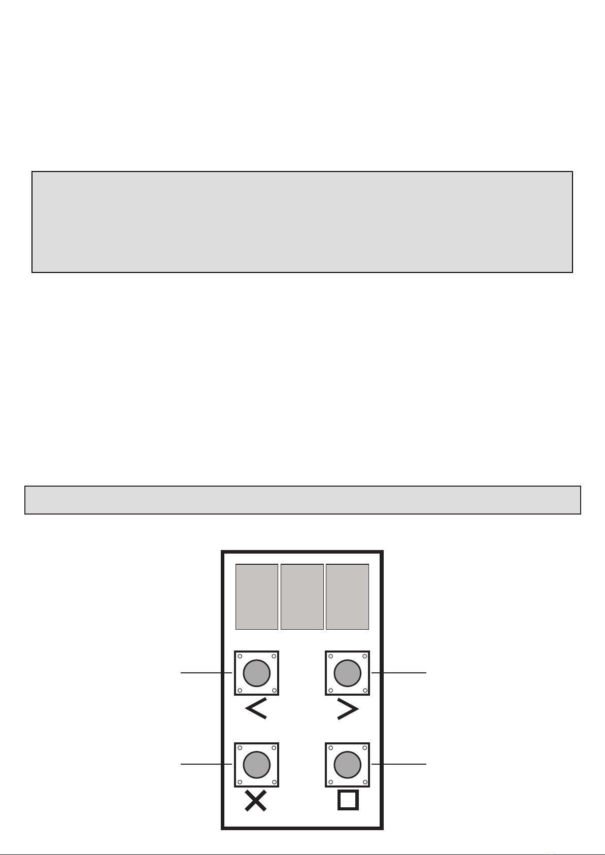
Using the control card display and dashboard.
The Drive 300 is equipped with an LED display and interacve keys for simplied programming and diagnoscs. All setup of the various features requires
that the control card dashboard be used. Below are the funcons of each key on the dashboard.
rdy
Enter programming, advance to next
level of opon on display or save value
on display.
Exit menu levels without saving.
Navigate backward in menus, decrease
values or indicate lehand closing gate
in runme setup funcon.
Navigate forward in menus, increase
values or indicate righthand closing
gate in runme setup funcon. Test
BT mode seng from “ready” status.
Before connuing with the commisioning.
If you are unfamiliar with the funconality of this product’s modes, it is suggested that you
familiarise yourself with the basic and advanced operang features detailed from page 32
of this instrucon manual.
18
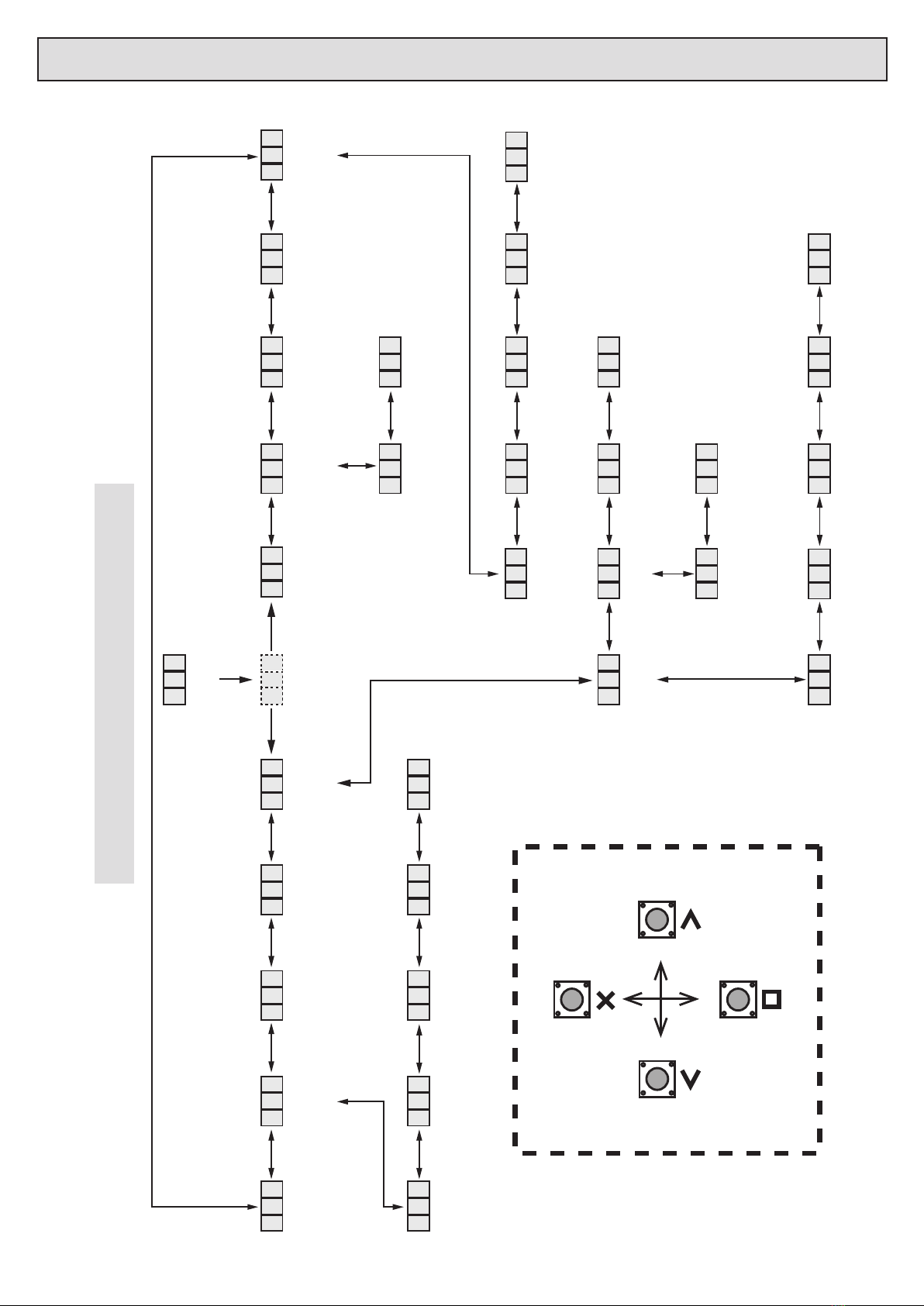
Control card programming and setup.
Programming menu quick reference guide:
Buon trigger
setup
Page 21
b t
Posive close
setup
Page 30
p c l
Auxiliary relay
setup
Page 31
r l y
Infra-red beam
setup
Page 20
i r b
Collision force
setup
Page 20
f o r
Power supply
setup
Page 29
p 5 u
Slow down
distance
Page 30
5 l o
Pedestrian
setup
Page 22
p e d
Ready status
Page 17
r d y
Programming
menu
p r 9
Runme
setup
Page 19
r u n
AC
monitoring
a c
Charger
On/Off
c h r
P.I.R.A.C
mode
p i r
Simple auto-close
mode
a u t
Standard
mode
5 t d
Condominium
mode
c o n
Courtesy light
mode
l i t
Receiver relay
mode
r c
Mag-lock
mode
l c 2
Strike lock
mode
l c 1
Tamper alarm
mode
a l a
Corresponding
buon learn
c o r
Version
informaon
i n f
Holiday lock out
channel
h o l
Diagnosc
tool
d i a
Erase all
a l l
Auxiliary relay
channel
r l y
Erase
menu
e r a
Erase
address
a d r
Pedestrian
channel
p e d
Receiver
setup
Page 23
r c
Learn
menu
l r n
Buon trigger
channel
b t
P.I.R.A.C + Condo
mode
p - c
Exit
Set
Le Right
19
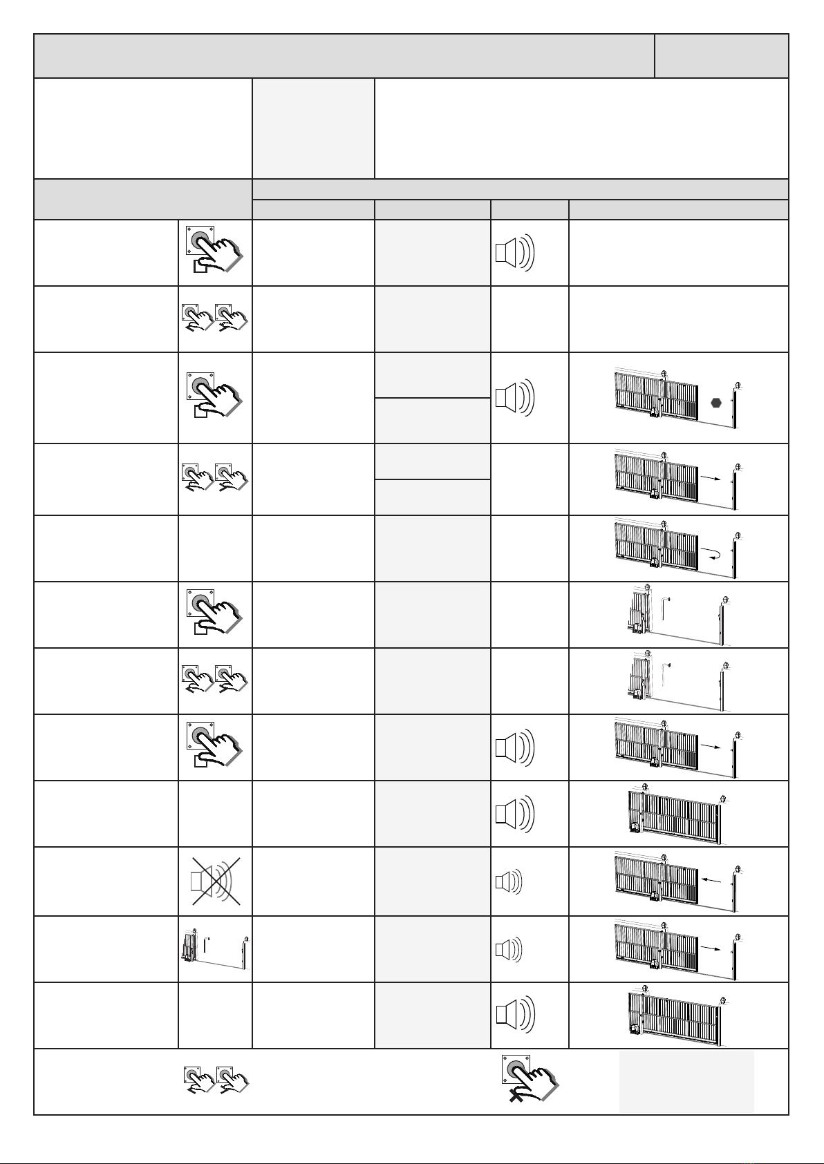
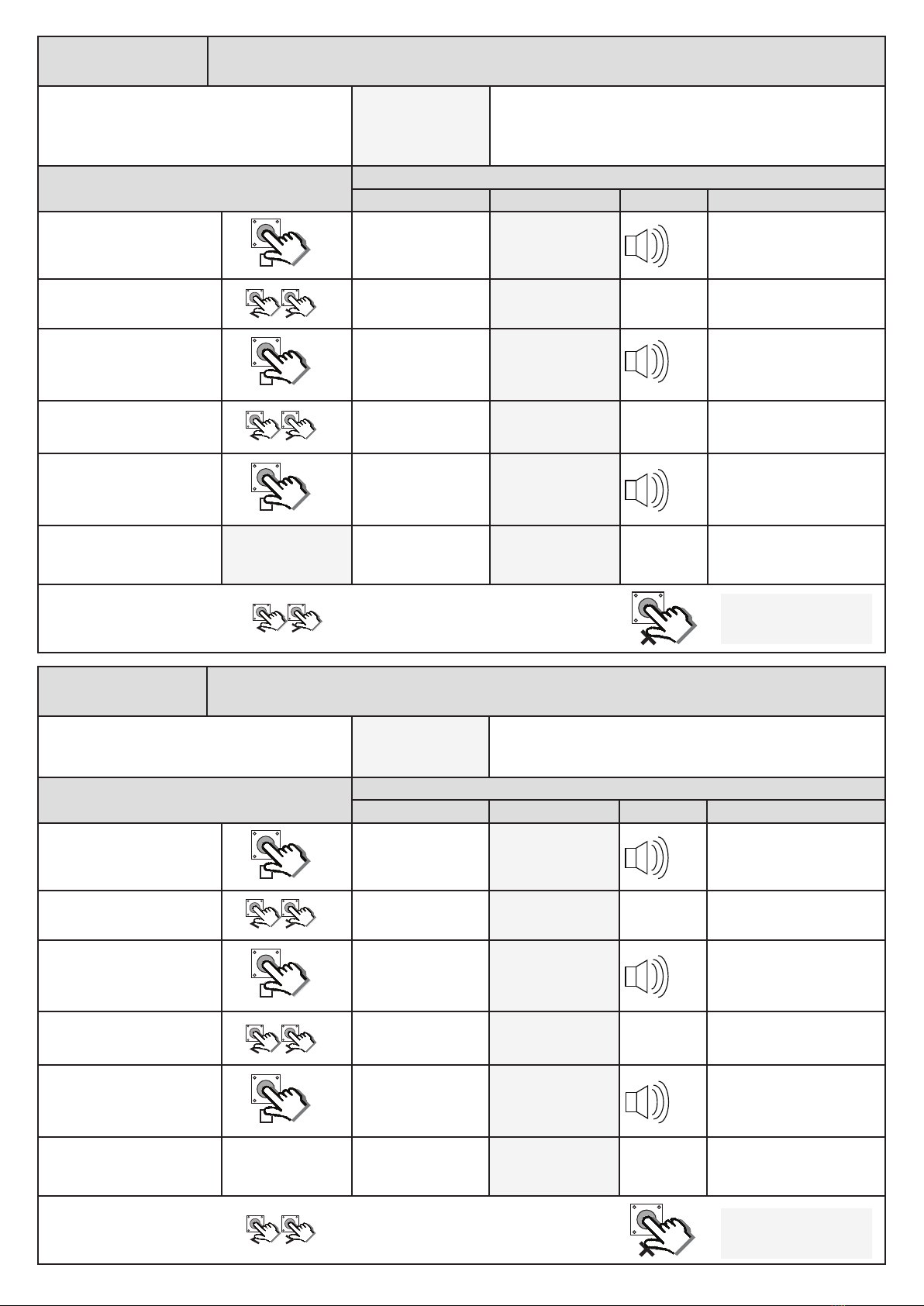
Seng up the gate runme. (Mandatory) run
From Ready status rdy
Before connuing with the runme setup ensure the limit actuator has
been installed correctly as per page 16 in this manual. Begin with the
gate midway in its travel.
NB. To speed up the gate while running during this procedure, press and hold
either the < or > buons.
Acon Response
Descripon Display Buzzer Gate/s
To enter the program
menu. Press and hold the
buon unl buzzer
beeps.
Display and buzzer
conrms. pr9
Scroll < or > to select the
runme setup opon.
Display scrolls
through opons. run
Ensure gate is engaged
midway and then press
buon.
Display prompts
you to conrm gate
closing direcon.
cl
dir
Conrm gate closing
direcon by pressing and
releasing either the < or >
buon.
Gate closes slowly.
Display conrms.
Lft
r9t
When the closed posion
is reached and the closed
limit is triggered. LED on.
Gate stops and starts
opening. lrn
Press and release the
buon to stop the gate
at the required open
posion.
Gate stops opening.
Display asks you to
ne adjust the open
posion if required. adj
Fine adjust the open
posion using the < or >
buons, if necessary.
Gate moves with
each buon press in
either direcon. adj
When sased with the
open posion, press and
release the buon to
save that posion.
Gate closes slowly.
Display and buzzer
conrms. lrn
When the closed posion
is reached and the closed
limit is triggered. LED on.
Gate stops. Display
and buzzer warn the
proling is about to
begin. pro
Once warning tone has
stopped.
Gate begins running
open at full speed.
Display conrms. pro
When the previously
programmed open
posion is reached.
Gate stops and
begins closing again
at full speed. Display
conrms. pro
When the closed posion
is reached and the closed
limit is triggered. LED on.
Gate stops. Display
and buzzer conrms. dne
x2
x1 STOP
x1
x1
On/o...
On/o...
x2
Scroll le or right to next
program opon. OR rdy
EXIT back to ready
status
20
for Selecng a safety level.
From Ready status rdy
This adjusts the force level, over and above the nominal gate
resistance, needed to trigger the safety overload rounes.
Level 1 being the most sensive and 8 being the least sensi-
ve. The factory default is level 3.
Acon Response
Descripon Display Buzzer Gate
To enter the program menu.
Press and hold the buon
unl buzzer beeps.
Display and buzzer
conrms. pr9
Scroll < or > to select the
collision force setup opon.
Display scrolls
through opons. for
With “For” on the display,
press and release .
Display shows current
opon status. 003
Scroll < or > to the required
seng.
Display changes
respecvely. 006
With required seng
displayed, press and release
.
Display briey shows
the new seng is
saved. 006
Aer display conrms new
seng. 006 Display returns to
programming menu
opons list. for
x2
x1
x2
Scroll le or right to next
program opon. OR EXIT back to Ready
status rdy
irb Safety infra-red beams setup.
From Ready status rdy Use this opon to enable the safety beam circuit. The safety
beams circuit must be congured as per page 15 with the
end of line resistor installed.
Acon Response
Descripon Display Buzzer Gate
To enter the program menu.
Press and hold the buon
unl buzzer beeps.
Display and buzzer
conrms. pr9
Scroll < or > to select the
beam setup opon.
Display scrolls
through opons. irb
With “irb” on the display,
press and release .
Display shows current
opon status. off
Scroll < or > to toggle
between “on” or “o”.
Display changes
respecvely. on
With required seng
displayed, press and release
.
Display briey shows
the new seng is
saved. on
Aer display conrms new
seng.
Beam Setup
Enabled Saved
Display returns to
programming menu
opons list. irb
x2
x1
x2
Scroll le or right to next
program opon. OR pr9
EXIT back to standby
status
Table of contents
Other E.T. Systems Gate Opener manuals


Popular Gate Opener manuals by other brands


Viking Access Systems
Viking Access Systems K-2 installation instructions

Portamatik
Portamatik TOP500 User's and installer's manual

SEA
SEA Libra Mini Tank INSTALLATION MANUALS AND SAFETY INFORMATION

Eagle Access Control Systems
Eagle Access Control Systems X9S Installation & owner's manual

Toona
Toona TO6024HS Instructions for installation and use

Dea
Dea LIVI 403E Operating instructions and warnings


