E2S BExS110D-SIL User manual

INSTRUCTION MANUAL
BExS110D-SIL
ALARM HORN SOUNDER –SIL2
ATEX, IECEx & UKEx GAS & DUST
E2S Warning Signals Impress House, Mansell Road, Acton, London W3 7QH
www.e2s.com
Tel: +44 (0)208 743 8880
Document No. D210-00-651-IS
Issue 1
13-01-23
Sheet 1 of 13
1) Product Table
Model Number
Nominal
Input Voltage
Nominal
Input Current
Voltage Range
Sound
Pressure Level dB(A)
Max*
Nom.†
BExS110DFDC024-SIL
24Vdc
290mA
20-28Vdc
117dB(A)
Flare:
110dB(A)
*Max = Tone 4
†Nom. = Tone 44
The table shows the input current taken by the various sounders.
The current levels shown above are for the 440Hz Continuous tone @ nominal input voltage.
Nominal current at nominal voltage.
Table 1: Electrical Ratings.
It is important that a suitable power supply is used to run the equipment. The power supply selected must have the necessary
capacity to provide the input current to all of the units.
The above table shows the input current taken by the various sounders and shows the maximum voltage at which the sounders can
be operated:
The input current will vary according to the voltage input level and the frequency of the tone selected.
BExS110D-SIL

E2S Warning Signals Impress House, Mansell Road, Acton, London W3 7QH
www.e2s.com
Tel: +44 (0)208 743 8880
Document No. D210-00-651-IS
Issue 1
13-01-23
Sheet 2 of 13
2) Warnings
•DO NOT OPEN WHEN AN EXPLOSIVE ATMOSPHERE
IS PRESENT
•DO NOT OPEN WHEN ENERGIZED
•POTENTIAL ELECTROSTATIC CHARGING HAZARD
•COVER BOLTS CLASS A4-80
•USE HEAT RESISTING CABLES AND CABLE GLANDS
(RATED 110°C) AT AMB. TEMPERATURES OVER 40°C
3) Marking & Rating Information
The BExS110D & BExS110D-R Alarm Horns comply with the
following standards for hazardous locations:
3.1. ATEX / IECEx & UKEx Ratings
Standards
EN60079-0:2018/IEC60079-0:2017 (ed.7):
Explosive Atmospheres - Equipment General Requirements.
EN60079-1:2014/IEC60079-1:2014 (ed.7):
Explosive Atmospheres - Equipment Protection by
Flameproof Enclosures “d”.
EN60079-31:2014/IEC60079-31:2013 (ed.2):
Explosive Atmospheres - Equipment Dust Ignition Protection
by enclosure “t”.
Model No:
Rating
BExS110D-SIL
Ex db IIC T4 Gb Ta. -50°C to +55°C
Ex db IIB T4 Gb Ta. -50°C to +70°C
Ex tb IIIC T100°C Db Ta. -50°C to +55°C
Ex tb IIIC T115°C Db Ta. -50°C to +70°C
See Product table for electrical ratings of each unit model
Certificate No.
KEMA 99ATEX6312X
IECEx KEM 10.0003X
UL22UKEX2638X
Epsilon x
Equipment Group
and Category:
II 2G
II 2D
CE Marking and
Notified Body No.
2813
UKCA Marking and
Approval Body No.
0518
4) Zones, Gas Group, Category and
Temperature Classification
The units can be installed in locations with the following conditions:
Area Classification Gas
Zone 1
Explosive gas air mixture likely to occur in normal
operation.
Zone 2
Explosive gas air mixture not likely to occur in
normal operation, and if it does, it will only exist for
a short time.
Gas Groupings
Group IIA
Propane
Group IIB
Ethylene
Group IIC
Hydrogen and Acetylene (up to 55°C ambient)
Temperature Classification for Gas Applications
T1
450oC
T2
300oC
T3
200oC
T4
135oC
Area Classification Dust
Zone 21
Explosive dust air mixture likely to occur in normal
operation.
Zone 22
Explosive dust air mixture not likely to occur in
normal operation, and if it does, it will only exist for
a short time.
Dust Groupings
Group IIIA
Combustible Dusts
Group IIIB
Non-Conductive Dusts
Group IIIC
Conductive Dusts
Equipment Category
2G, 2D
Equipment Protection Level
Gb, Db,
Maximum Surface Temperature for Dust Applications
100°C at +55°C
115°C at +70°C
Ambient Temperature Range
-50°C to +55°C Gas Groups IIA, IIB and IIC
-50°C to +70°C Gas Groups IIA and IIB
-50°C to +70°C Dust Groups IIIA, IIIB and IIIC
IP Rating
IP66/67 to EN/IEC60529 and
IP6X to EN/IEC60079-0, EN/IEC60079-31
The sounder must only be installed by suitably qualified personnel in
accordance with the latest issues of the relevant standards:
EN60079-14 / IEC60079-14:
Explosive atmospheres - Electrical installations design,
selection and erection
EN60079-10-1 / IEC60079-10-1:
Explosive atmospheres - Classification of areas. Explosive gas
atmospheres
EN60079-10-2 / IEC60079-10-2:
Explosive atmospheres - Classification of areas. Explosive dust
atmospheres
The installation of the sounder must also be in accordance with any
local codes that may apply and should only be carried out by a
competent electrical engineer who has the necessary training.

E2S Warning Signals Impress House, Mansell Road, Acton, London W3 7QH
www.e2s.com
Tel: +44 (0)208 743 8880
Document No. D210-00-651-IS
Issue 1
13-01-23
Sheet 3 of 13
5) Special Conditions of Use
Repair of the flamepath / flameproof joints is not permitted.
The enclosure is non-conducting and may generate an
ignition-capable level of electrostatic charges under certain
extreme conditions (such as high-pressure steam). The user
should ensure that the equipment is not installed in a location
where it may be subjected to external conditions that might
cause a build-up of electrostatic charges on non-conducting
surfaces.
Additionally, cleaning of the equipment should be done only
with a damp cloth.
6) Location and Mounting
The location of the sounder should be made with due regard
to the area over which the warning signal must be visible.
They should only be fixed to services that can carry the
weight of the unit.
The BEx sounder should be secured to any flat surface using
the three 7mm fixing holes on the stainless steel U shaped
mounting bracket. See Figure 1. The required angle can be
achieved by loosening the two large bracket screws in the
side of the unit, which allow adjustment of the sounder in
steps of 18°. On completion of the installation then two large
bracket adjustment screws on the side of the unit must be
fully tightened to ensure that the unit cannot move in service.
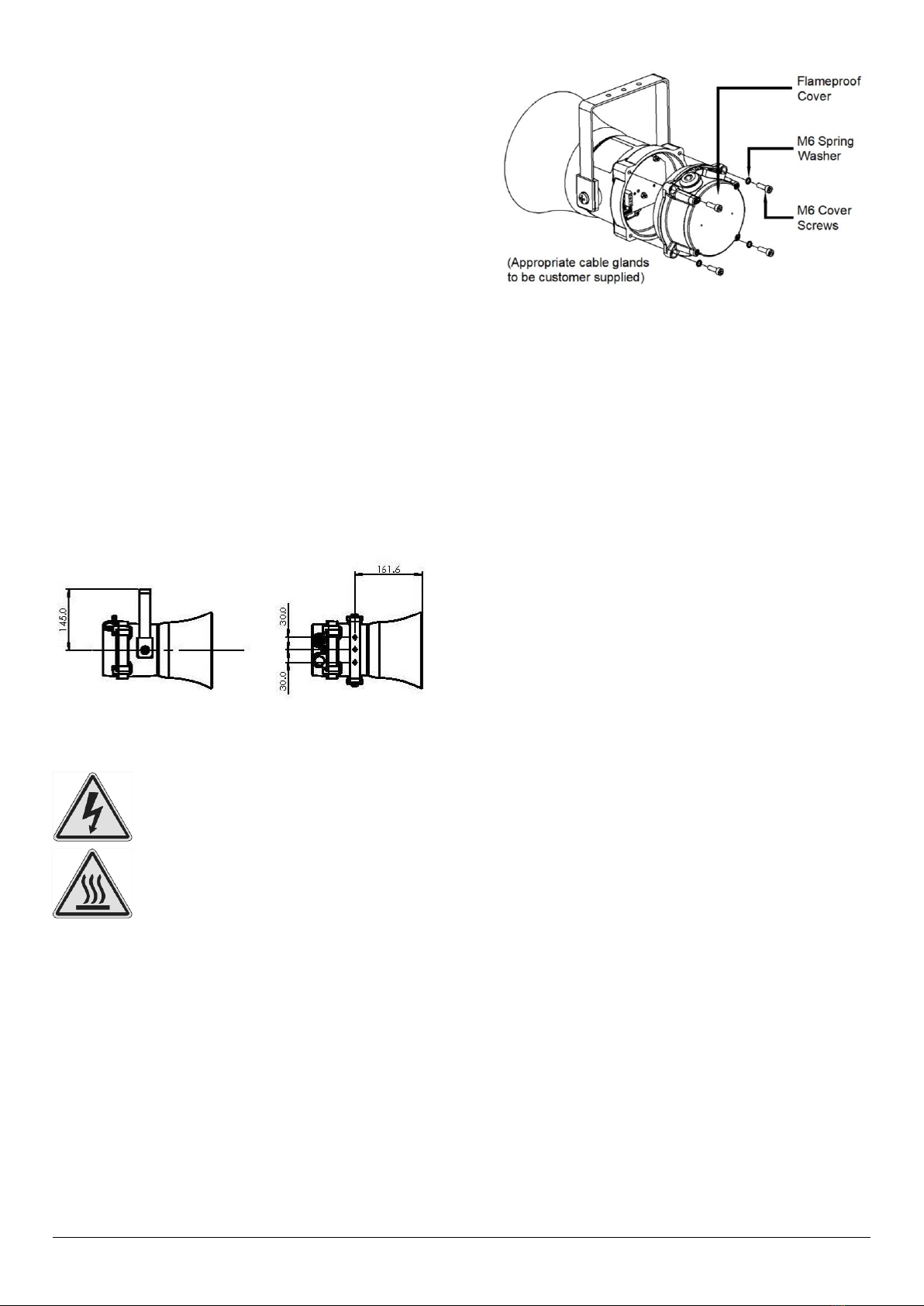
Fig. 1 Fixing Location for S110 Sounder
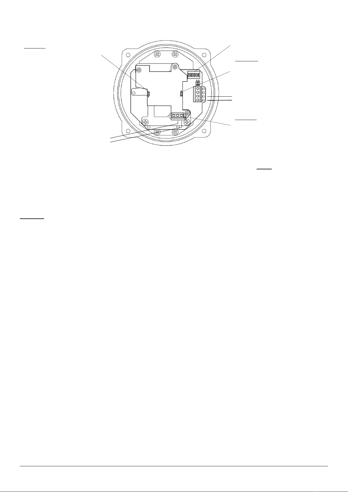
7) Access to the Flameproof Enclosure
To access the Ex d chamber, remove the four M6 hexagon
socket head screws and withdraw the flameproof cover taking
extreme care not to damage the flameproof joints in the
process. M6 cover screws are Class A4-80 stainless steel
and only screws of this category can be used for the
enclosure.
Fig. 2 Accessing the Explosion proof Enclosure.
On completion of the installation, the flameproof joints should
be inspected to ensure that they are clean and that they have
not been damaged during installation.
Check that the earth bonding wire between the two castings
is secure and the ‘O’ ring seal is in place. When replacing the
flameproof cover casting ensure that it is square with the
flameproof chamber casting before inserting. Carefully push
the cover in place allowing time for the air to be expelled.
Only after the cover is fully in place should the four M6
Stainless Steel A4-80 cover bolts and their spring washer be
inserted and tightened down. If the cover jams while it is
being inserted, carefully remove it and try again. Never use
the cover bolts to force the cover into position.
8) Selection of Cable, Cable Glands,
Blanking Elements & Adapters
When selecting the cable size, consideration must be given
to the input current that each unit draws (see table 1), the
number of sounders on the line and the length of the cable
runs. The cable size selected must have the necessary
capacity to provide the input current to all of the sounders
connected to the line.
For ambient temperatures over +40ºC the cable entry
temperature may exceed +70ºC and therefore suitable heat
resisting cables and cable glands must be used, with a rated
service temperature of at least 110ºC
The dual cable gland entries have an M20 x 1.5 entry thread.
To maintain the ingress protection rating and mode of
protection, the cable entries must be fitted with suitably rated
ATEX / IECEx & UKEx certified cable glands and/or suitably
rated ATEX / IECEx & UKEx certified blanking devices during
installation according to EN / IEC60079-14.
If a high IP (Ingress Protection) rating is required then a
suitable sealing washer must be fitted under the cable glands
or blanking plugs.
For use in explosive dust atmospheres, a minimum ingress
protection rating of IP6X must be maintained.
The BEx sounder range can be supplied with the following
types of adapters:
M20 to ½” NPT
M20 to ¾” NPT
M20 to M25
It is important to note that stopping plugs cannot be fitted
onto adapters, only directly onto the M20 entries.
Any other adapters used must be suitably rated and ATEX /
IECEx & UKEx certified adapters.
Warning –Hot surfaces. External surfaces
and internal components may be hot after
operation, take care when handling the
equipment.
Warning –High voltage may be present,
risk of electric shock. DO NOT open when
energised, disconnect power before
opening.

E2S Warning Signals Impress House, Mansell Road, Acton, London W3 7QH
www.e2s.com
Tel: +44 (0)208 743 8880
Document No. D210-00-651-IS
Issue 1
13-01-23
Sheet 4 of 13
9) Earthing
DC sounder units must be connected to an earth. The units
are provided with internal and external earth terminals which
are both located on the terminal chamber section of the unit.
Fig. 3 Internal View of Cover
When using the internal earth terminal ensure that the
stainless steel M4 flat washer is between the incoming earth
wire and the enclosure.
Internal earthing connections should be made to the Internal
Earth terminal in the base of the housing using a ring crimp
terminal to secure the earth conductor under the earth clamp.
The earth conductor should be at least equal in size and
rating to the incoming power conductors. Tighten M4 Earth
screw to 1Nm.
External earthing connections should be made to the M5
earth stud, using a ring crimp terminal to secure the earth
conductor to the earth stud. The external earth conductor
should be at least 4mm² in size. Tighten the Earth nut to
3Nm. Please firmly tighten the external grounding terminal so
that the stud does not become loose and lay the ground wire
so that it is not caught by twisting and sagging.
10) Cable Connections
Electrical connections are to be made into the terminal blocks
on the PCBA located in the flameproof enclosure. See
section 7 of this manual for access to the flameproof
enclosure.
Wires having a cross sectional area between 0.5 mm² to
2.5mm² can be connected to each terminal way. If an input
and output wire is required the 2-off Live/Neutral or +/-
terminals can be used. If fitting 2-off wires to one terminal
way the sum of the 2-off wires must be a maximum cross
sectional area of 2.5mm². Strip wires to 8mm. Wires may also
be fitted using ferrules. Terminal screws need to be tightened
down with a tightening torque of 0.45 Nm / 5 Lb-in. When
connecting wires to the terminals great care should be taken
to dress the wires so that when the cover is inserted into the
chamber the wires do not exert excess pressure on the
terminal blocks. This is particularly important when using
cables with large cross sectional areas such as 2.5mm².
11) DC Wiring
A 4-way terminal block is provided on the DC Sounder. There
are 1-off +ve, 1-off -ve, 1-off stage 2 and 1-off stage 3
terminals in total.
Fig. 4 S110 DC Terminals
Refer to D210-06-651 for schematic diagram.
11.1. Stage Switching Polarity (DC Units)
The BExS110D DC sounders have the facility to use either
+ve or –ve switching to change the tone to the second and
third stages. Negative switching is the default setting. For –ve
switching connect the two headers on the pcb to the left-hand
(marked –ve) and centre pins. For +ve switching connect the
headers to the right hand (marked +ve) and the centre pins.
(Refer to Fig. 5)
Fig. 5 Stage Switching Polarity
Refer to D210-06-651 for schematic diagram.

E2S Warning Signals Impress House, Mansell Road, Acton, London W3 7QH
www.e2s.com
Tel: +44 (0)208 743 8880
Document No. D210-00-651-IS
Issue 1
13-01-23
Sheet 5 of 13
11.2. Line Monitoring
On BExS110D DC units, dc reverse line monitoring can be
used if required. All DC sounders have a blocking diode fitted
in their supply input lines. An end of line monitoring diode or
an end of line monitoring resistor can be connected across
the +ve and –ve terminals. If an end of line resistor is used it
must have a minimum resistance value of 3k3Ω and a
minimum power rating of 0.5 watts or a minimum resistance
value of 500Ω and a minimum power rating of 2 watts.
The resistor must be connected directly across the +ve and -
ve terminals as shown in the following drawing. The resistor
leads should be kept as short as possible.
SIL2 line monitoring module product version: see section 22
for standard default values and product coding. See
document D210-06-651 for associated wiring diagram.
Fig. 6 End of Line Resistor Placement
Note that the maximum forward polarity monitoring voltage is
6V. A monitoring voltage greater than 6V may activate the
alarm horn sounder and the 2nd or 3rd stages.
12) Tone Settings
BExS110D-SIL sounders need to be set to one off the SIL 2
approved tones to work correctly with the automated sounder
check on pattern generation and signal output checks.
Default =
Tone 1
0 0 0 0 0 0
(ON = 1, OFF = 0)
Figure 7: DIP switch configuration
Refer to D210-95-651-IS Tone Table for tone selection.
Table 2 below is a summary of DC: D210-06-651 wiring
options.
12.1. Volume Control (None)
BExS110D-SIL sounder has no volume control, as the unit is
monitoring its output the volume cannot be adjusted.
13) Maintenance, Overhaul & Repair
Maintenance, repair and overhaul of the equipment should
only be carried out by suitably qualified personnel in
accordance with the current relevant standards:
EN60079-19
IEC60079-19
Explosive atmospheres - Equipment repair,
overhaul and reclamation
EN 60079-17
IEC60079-17
Explosive atmospheres - Electrical
installations inspection and maintenance
The acoustic horn is made out of ABS plastic, therefore to
avoid a possible ELECTROSTACTIC CHARGE the unit must
only be cleaned with a damp cloth.
Units must not be opened while an explosive atmosphere is
present.
If opening the unit during maintenance operations a clean
environment must be maintained and any dust layer removed
prior to opening the unit.
Config.
Voltage
Configuration Description
Features
Product
Option
Identifier
1a
DC
Single Stage Configuration
•Line monitoring
•Negative Switching
1
1b
DC
Two or Three Stage Configuration
•Common Positive
•Negative Switching
1
2
DC
Two or Three Stage Configuration
•Common Negative
•Customer to Set Header Pins to Positive
Switching
1
Table 2: Summary of Wiring Options. See Document D210-06-651 for DC Schematic Diagrams.

E2S Warning Signals Impress House, Mansell Road, Acton, London W3 7QH
www.e2s.com
Tel: +44 (0)208 743 8880
Document No. D210-00-651-IS
Issue 1
13-01-23
Sheet 6 of 13
14) SIL 2 Instruction/Safety Manual
Figure 8 - The SIL 2 Module monitors the Sounder and interfaces to the customer plant.
Warning –To maintain the integrity of the SIL 2 units the system must be installed, commissioned and used within the parameters outlined in this
manual. Failure to comply could result in an unintended unit operation or function.
Warning –The unit must be powered in either Standby or Active modes to comply with the SIL 2 approval requirement.
If the power is disrupted the unit must be allowed to go through the commissioning cycle to reset.
Failure to complete the commissioning cycle and continued disruption in the power supply will generate a fault state which will require the
sounder to be reset (see section 18-4).
Warning –Only the alarm tones specified in section 17 may be selected for use in SIL2 compliant systems.
SIL 2 System Description
The SIL 2 module monitors the function of the device and
provides feedback to the control panel. A fault condition can
be communicated by two methods:
•4 wire installation can be seen as per section 18-1.
A SIL 2 system wiring for fault detection in standby
and active mode with independent fault contacts.
•2 wire installation can be seen as per section 18-2.
A SIL 2 system by the introduction to the monitoring
circuit and linking in an end of line resistor can only
register the fault in standby mode.
15) SIL 2 System Terms and Function
The SIL 2 Sounder Unit Monitors
•Standby mode and Active mode
•Health status of power supply
•Sounder correct function and tone pattern
The SIL 2 sounder operates as part of a SIL 2 system.
The sounder will after commissioning remain powered in
Standby mode (reverse polarity) until the sounder is required
to operate. When the signaling device is required to operate
the polarity is changed to normal supply and the sounder will
go into Active mode where it will start to sound the correct
tone. When periodically testing the system and sounders
operation is put into Active mode.
The system panel or PLC will control whether the system is in
either of the main two operational modes.
Standby Mode –This is where the power supply polarity is
reversed so negative (–ve) is feed to the positive (+) sounder
terminal and positive (+) is feed to the negative (–ve) sounder
terminal.
In Standby mode the sounder will not sound the tone but the
SIL 2 unit is monitoring power supply and is set-up ready to
go to Active (alarm) mode.
Power relay RLY1-1 will be open whilst SIL 2 relay RLY1-2
will be closed contact between terminals 1 & 2.
If power is disrupted the SIL 2 unit will go into Fault mode, in
fault mode the Power relay RLY1-1 will close whilst SIL 2
relay RLY1-2 will become open circuit between terminals 1 &
2.
Active Mode –This is where the power is in normal polarity,
positive (+) supplied to the positive (+) sounder terminal and
negative (–ve) is supplied to the negative (–ve) sounder
terminal.
In Active mode the alarm horn sounder will output the
selected alarm tone. The SIL 2 module checks for the correct
alarm tone output and the functionality of the alarm tone
signal generation process.
Power relay RLY1-1 will be open whilst SIL 2 relay RLY1-2
will be closed contact between terminals 1 & 2.
The SIL 2 unit will also check for signal polarity.
J3 HEADER PIN

E2S Warning Signals Impress House, Mansell Road, Acton, London W3 7QH
www.e2s.com
Tel: +44 (0)208 743 8880
Document No. D210-00-651-IS
Issue 1
13-01-23
Sheet 7 of 13
If a fault is found the SIL 2 unit will go into Fault mode.
If power is disrupted the SIL 2 unit will go into Fault mode, in
fault mode the Power relay RLY1-1 will close whilst SIL 2
relay RLY1-2 will become open be circuit between terminals
1 & 2.
Fault modes - The fault modes listed 15-1 & 15-2 below will
make the SIL 2 unit change the state for relays RLY1-1 and
RLY1-2.
In fault mode the Power relay RLY1-1 will close whilst SIL 2
relay RLY1-2 will become open circuit between terminals 1 &
2.
15-1 Sounder Failure
•Tone Failure –No Tone detected
•Sounder Controller failure –No tone generation
pulse detected
•Tone Rate Failure –Regular tone cycle erratic
15-2 Power Failure / SIL 2 Failure
•SIL 2 Controller failure –Internal function and
system checking flags fault
•Rapid Power cycling –System indicates power
instability
•Total Power Failure
It is possible to reset these faults if they were transitory.
Resetting Failure (by power cycling) - It is possible that the
SIL 2 unit can be reset by powering the unit off for a period
greater than 20 seconds. On restarting the unit and running
through the commissioning cycle the fault may clear.
Resetting Failure (by Hard Reset) - It is possible that the SIL
2 unit can be reset by hard resetting the unit using the reset
jumper within the unit (see section 18-4) on hard resetting.
On restarting the unit and running through the commissioning
cycle, the fault may clear. It is necessary to run the test
function cycle again to see if the fault is still evident.
If the hard reset process does not correct the latched fault the
alarm horn sounder may require further investigation, please
contact your local E2S representative.
Commissioning System - Functional start-up of System
(Normally in reverse polarity mode)
When Commissioning system the power must not be
disrupted to the SIL 2 Unit within the unit’s initialization cycle
which is 5 seconds.
Once past this period the SIL 2 system is fully operational
and will be in monitoring the sounder and power in Standby
mode.
The relay RLY1-2 on the SIL 2 unit will only remain open for a
maximum of 1 second on commissioning start-up. RLY1-2
will subsequently close contacts 1 & 2 indicating healthy
operation. Contact 1 & 2 will only remain open in the event of
a fault or a loss of power.
System Testing (Active Mode normal polarity)
The SIL 2 system will remain monitoring the power in standby
mode until the polarity is changed to normal mode to enable
an active system for sounder functional testing.
Important: - The polarity must be held in active mode for a
period in excess of 15 seconds to ensure a full system check
is performed.
Once the test period has been completed the unit can be
switched back to standby mode by reversing the polarity.
If no faults have been found during the test the relays will
remain in steady state.
The SIL 2 unit will continue to monitor the power and module
function.
Important: - The automated test cycle must be undertaken
on at least a weekly basis to maintain the SIL 2 units
reliability.
System Activation (Active Mode normal polarity)
The SIL 2 system will remain monitoring the power in standby
mode until the polarity is changed to Active mode to enable
an active system for sounder to function as a warning
signaling device.
Important :- The polarity must be held in active mode for a
period in excess of 15 seconds to ensure a full system check
is performed whilst in alarm mode, although it is expected
that during a system activation this period will be significantly
greater.
Note :- The fault indication signal on TB1 can take up to 50
milliseconds to indicate system fault.

E2S Warning Signals Impress House, Mansell Road, Acton, London W3 7QH
www.e2s.com
Tel: +44 (0)208 743 8880
Document No. D210-00-651-IS
Issue 1
13-01-23
Sheet 8 of 13
16) SIL 2 Wiring configuration and Sounder set-up
Figure 9 –Terminals and header pins for sounder
Power & Communication with the system control panel can be configured in two ways: - Although it is highly recommended that the
unit is wired as stated in this section 18-1 as a 4 –Wire System.
17) SIL 2 APPROVED TONE SELECTION
BExS110D-SIL sounders need to be set to one off the SIL 2 approved tones to work correctly with the automated sounder check on
pattern generation and signal output checks.
Important: - Only tones use tones that are stated as SIL 2 approved for the SIL 2 application. Ensure that the unit is set to one of
these tones see in Tone Table (D210-95-651-IS).
As factory default the sounder should be set to Stage 1 (Dip switch 000000).
2
1
Sounder Supply Terminals
-
+
J1 Header –Current Sense Resistor (CSR)
Shown in factory default position A
(see section 18-3), places SIL TB1 Current
sense resistor in circuit.
J3 Header –Hard Reset
Shown in factory default position A
(see section 18-4), set to
Normal operation
DIP Switch Tone Selection
SIL Relay Terminals TB1
J2 Header –Fault Resistor (FR)
Shown in factory default position A
(see section 18-3) removes power
supply terminal block. Fault resistor
& relay RLY 1-1out of circuit.

E2S Warning Signals Impress House, Mansell Road, Acton, London W3 7QH
www.e2s.com
Tel: +44 (0)208 743 8880
Document No. D210-00-651-IS
Issue 1
13-01-23
Sheet 9 of 13
18-1) SIL 2 system wiring for fault detection in standby and active mode –4 wire installation
(Recommended)
The customer is required to wire into both the sounder power supply terminals block and also the SIL 2 Relay terminals TB1
The power supply terminals only need to have the supply power connected. This will be reverse polarity for monitoring mode and
normal polarity for active mode. There is no need to fit an EOL resistor on the power supply terminal block as the TB1 is configured
to raise a fault alarm in any situation.
Terminal block TB1 is the output from the SIL 2 monitoring relay. Relay RLY 1-2 provides a closed circuit between TB1 terminals 1 &
2 whilst powered. On detection of a fault event this will become open circuit.
The fault will be seen via the SIL 2 TB1 terminals as soon as the fault occurs in either Active or Standby modes.
When no fault is detected the circuit to the SIL 2 TB1 terminals 1 & 2 will include a factory fitted 3.3K Ohm current sense resistor
(CSR) in series. When the circuit is driven with 24Vdc the detection current seen is ~7.3mA @ 24V.
The only other fault mode is if the cable goes short circuit where a short will be seen by the panel.
Option: Should the fault event output of RLY1-2 be required to operate as a switch, header J1 can be set to link pins 1 & 2 (see
figure 10) thereby removing the 3.3k Ohm current sense resistor (CSR) from the circuit.
Note: a cable short circuit will not be detectable in this configuration.
For one unit only:
Sounder power
supply terminal
block
Current drawn
(mA)
Active Mode
190mA
Standby Mode
25mA
SIL2
TB1 Current
Sense Resistor
value
Current drawn
(mA)
3.3kΩ
7.2mA
On fault mode, current drops to 0 as
circuit goes open.
Figure 10 - Schematic of SIL 2 system wiring for fault detection in standby and active mode –4 wire installation.
If multiple SIL 2 alarm horn sounders are to be cabled in series the monitoring connections differ from that of a single alarm horn
sounder. For more information see manual D197-00-651-IS available from the E2S website.
18-2) SIL 2 system wiring for fault detection in standby mode only –2 wire installation
Cabling is required to the positive '+' and negative '-' power input terminals only. Monitoring will occur in standby mode only whilst
power supply polarity is reversed. An EOL resistor may be added during installation or can be factory fitted. See Table 3 for EOL
resistor value guidance.
The SIL2 monitoring module contains a factory fitted Power Supply Fault Resistor 2.2K Ohm (FR). When a fault is detected the Fault
Resistor will activated. The total measurable resistance of the EOL resistor and Fault Resistor across the power terminals which
already has customer EOL resistor (2.2kΩ) in place. This will result in a total fault detection current of 41.8mA @ 24V but can only
be detected when unit is in Standby Mode.
Important: - The 2 wire configuration will not warn of a fault whilst in Active mode. A fault will only be detectable in standby mode
when power supply polarity is reversed.
Important: - The 2-wire configuration requires the J2 header pin to be set to position B (see figure 13). Factory default position is A.

E2S Warning Signals Impress House, Mansell Road, Acton, London W3 7QH
www.e2s.com
Tel: +44 (0)208 743 8880
Document No. D210-00-651-IS
Issue 1
13-01-23
Sheet 10 of 13
Figure 11 - Schematic of SIL 2 system wiring for fault detection in standby mode only –2 wire installation
To evaluate the total current drawn from the SIL 2 unit, use the equation below.
In standby mode, where there is no fault, RLY 1-1 is open. This means the voltage only passes through the customer EOL resistor
and the current drawn from the SIL 2 board is 25mA. Therefore, the equation for a No Fault scenario is then:
In standby mode, where there is a fault, the circuit is closed. This means the voltage passes through both the customer EOL resistor
and current sense resistor and the current drawn from the SIL 2 board is 20mA. The customer must first calculate the resistance of
the two resistors in parallel before applying the currents to the equation. The equation for a Fault scenario is then:
Table 3: Resistor combinations and the currents drawn when no faults and faults occur
If multiple SIL 2 alarm horn sounders are to be cabled in series the monitoring connections differ from that of a single alarm horn
sounder. For more information see manual D197-00-651-IS available from the E2S website.
I
(Total Current
drawn)
=
(Current drawn from
Fault Resistor)
+
(Current drawn from
Customer EOL resistor)
+
(Current drawn
from SIL board)
(Standby Mode, Total Current drawn - No Fault)
=
(0mA)
+
(See table 3)
+
(25mA)
(Standby Mode, Total Current drawn - Fault)
=
(Total Resistance when EOL & FR in parallel)
+
(20mA)
Standb
y Mode
Power Supply Fault
Resistor
Customer EOL Resistor
(Fault Mode Only)
Current
drawn
from SIL
Board
Total
current
drawn
Resistor
Value
Current
drawn ( )
Resistor
Value
Current
drawn ( )
Total
resistance
Current
drawn ( )
No
Fault
2.2 kΩ
0 mA
2.2 kΩ
10.9 mA
-
-
25 mA
35.9 mA
Fault
-
-
1.1 kΩ
21.8 mA
20 mA
41.8 mA
No
Fault
1.0 kΩ
0 mA
1.0 kΩ
24.0 mA
-
-
25 mA
49.0 mA
Fault
-
-
500 Ω
48.0 mA
20 mA
68.0 mA
No
Fault
2.2 kΩ
0 mA
3.3 kΩ
7.3 mA
-
-
25 mA
32.3 mA
Fault
-
-
1.3 kΩ
18.2 mA
20 mA
38.2 mA
No
Fault
1.8 kΩ
0 mA
3.9 kΩ
6.2 mA
25 mA
31.2 mA
Fault
-
-
1.2 kΩ
19.5 mA
20 mA
39.5 mA
No
Fault
1.8 kΩ
0 mA
4.7 kΩ
5.1 mA
-
-
25 mA
30.1 mA
Fault
-
-
1.3 kΩ
18.4 mA
20 mA
38.4 mA
No
Fault
2.2 kΩ
0 mA
4.7 kΩ
5.1 mA
-
-
25 mA
30.1 mA
Fault
-
-
1.5 kΩ
16.0 mA
20 mA
36.0 mA

E2S Warning Signals Impress House, Mansell Road, Acton, London W3 7QH
www.e2s.com
Tel: +44 (0)208 743 8880
Document No. D210-00-651-IS
Issue 1
13-01-23
Sheet 11 of 13
18-3) Header Pins Settings
J1 Header Pin - Position A
Factory default position (pins 1 & 2 not linked)
Places TB1 Current Sense Resistor (CSR) in circuit.
As used in 4 - Wire Configuration
J1 Header Pin - Position B
(pins 1 & 2 linked)
Removes TB1 Current Sense Resistor (CSR) out of circuit.
Figure 12: J1 Header pin positions –Current Sense Resistor (CSR)
J2 Header Pin - Position A
Factory default position (pins 1 & 2 linked)
Removes power supply terminal Fault Resistor (FR) & RLY
1-2 out of circuit.
As used in 4 -Wire Configuration
J2 Header Pin - Position B
(pins 2 & 3 linked)
Places power supply terminal Fault resistor & RLY 1-2 in
circuit.
As used in 2 –Wire Configuration
Figure 13: J2 Header pin positions –Fault Resistor (FR)
18-4) SIL 2 Hard Reset Function
Power down the unit completely for a minimum of 30 seconds. Move the hard reset header pin (Jumper J3) to reset position B
shown. Then power the unit for a minimum of 5 seconds. Power down the unit for 30 seconds and then move the header pin back to
Position A.
The unit has now been reset.
If the hard reset process does not correct the latched fault the alarm horn sounder may require further investigation, please contact
your local E2S representative.
J3 Header Pin - Position A
Factory default position (pins 2 & 3 linked)
Hard Reset Function disabled –Normal Operation
J3 Header Pin - Position B
(pins 1 & 2 linked)
Hard Reset Enabled - Active reset mode
Figure 14: J3 Header pin positions –Hard Reset Function

E2S Warning Signals Impress House, Mansell Road, Acton, London W3 7QH
www.e2s.com
Tel: +44 (0)208 743 8880
Document No. D210-00-651-IS
Issue 1
13-01-23
Sheet 12 of 13
19) SIL 2 Specific Unit Mounting Requirements
The sounder should be mounted no closer that 5m from a sounder source of similar SPL output. This is to ensure false tone
activation does not occur when the unit is monitoring the tone pulse duration and tone failure.
20) SIL 2 Reliability Data
Reliability and Functional safety IEC/EN61508 which has been assessed and is considered suitable for use in low demand safety
function:
1. Random Hardware Failures and Architectural constraints (route 1H)
2. As an unvoted item (i.e. hardware fault tolerance of 0) at SIL 2
The product was assessed against failure modes:
•Failure respond to an input with a correct tone.
•Failure to respond to an input even with an alternative tone.
•Spurious sound output despite no input.
BExS110D-SIL (Failure to Sound)
Integrity in respect of failure to release
SIL 2
Total Failure rate
0.304 pmh
“hazardous” failure rate (revealed)
0.233 pmh
“hazardous” failure rate (unrevealed)
0.017 pmh
“safe” failure rate (revealed)
0
“safe” failure rate (unrevealed)
0
Diagnostic Coverage
93%
System type
B
Hardware Fault Tolerance
0
Safe Failure Fraction
>93%
PFD (hazardous failure)
9.4 x 10⁻⁵
Proof Test Interval
Up to 1 week
BExS110D-SIL (Failure to Sound or Incorrect tone)
Integrity in respect of failure to release
SIL 2
Total Failure rate
0.304 pmh
“hazardous” failure rate (revealed)
0.235 pmh
“hazardous” failure rate (unrevealed)
0.005 pmh
“safe” failure rate (revealed)
0.01
“safe” failure rate (unrevealed)
0
Diagnostic Coverage
98%
System type
B
Hardware Fault Tolerance
0
Safe Failure Fraction
>98%
PFD (hazardous failure)
2.0 x 10⁻⁵
Proof Test Interval
Up to 1 week
Table 4: SIL 2 Failure Rate
21) Synchronised Operation
All BExS110D-SIL alarm horn sounders connected to the same power supply and set to the same alarm tone will provide a
synchronised output when activated.

E2S Warning Signals Impress House, Mansell Road, Acton, London W3 7QH
www.e2s.com
Tel: +44 (0)208 743 8880
Document No. D210-00-651-IS
Issue 1
13-01-23
Sheet 13 of 13
22) Product Coding for Fault Resistor and Customer EOL Resistor
The customer is able to identify the resistor values chosen on purchase from the product code.
This is represented by the last three characters:
BExS110DFDC024AB1S1R-AFZ
•The first A character denotes the value of the Fault Resistor (FR) Default value is 2.2 kΩ (Code = A) unless an alternative
value is requested when ordering.
•The second F character denotes the value of the Current Sense Resistor (CSR) Default value is 3.3 kΩ (Code = F) unless
an alternative value is requested when ordering.
•The third Z character denotes the value of the unit End Of Line Resistor (EOL) By default no EOL is fitted (Code = Z) A
factory fitted EOL resistor can be specified when ordering.
The values of resistors available are shown in table 5 below.
Code
Resistor Value
Three digit resistor coding as follows.
BExS110DFDC024AB1S1R -AFZ
Example of a custom requirement resistor coding:
BExS110DFDC024AB1S1R -GEF
Where the (FR) Fault Resistor is (G = 3.9 kΩ)
(CSR) Current Sense Resistor is (E = 2.7 kΩ)
(EOL) End Of Line resistor is (F = 3.3 kΩ)
Two digit resistor coding on other units.
BExS110DFDC024AB1S1R -AZ
Where the (FR) Fault Resistor is (A = 2.2 kΩ)
(EOL) End Of Line resistor is (Z = none fitted)
A
2.2 kΩ
B
1.0 kΩ
C
1.5 kΩ
D
1.8 kΩ
E
2.7 kΩ
F
3.3 kΩ
G
3.9 kΩ
H
4.7 kΩ
J
5.6 kΩ
K
6.8 kΩ
L
8.2 kΩ
M
11 kΩ
Z
None Fitted
Table 5: Resistor Value code
Note: Customers who have previously acquired BExS110D-SIL sounders with the two-character resistor code system (-XX) may
continue to use their E2S product code reference to repeat purchase orders. In the two-character code, the first character denotes
the value of the Fault Resistor (FR) and the second character denotes the value of the EOL resistor.
Note: To utilise the full monitoring functionality the 4-wire configuration is recommended. An EOL resistor is not required for this
configuration.
The alternative 2-wire configuration requires an EOL resistor to be fitted. The EOL resistor can be specified during ordering and
factory fitted or selected and fitted during the alarm horn sounder installation.
See section 11 for EOL resistor location and wattage requirements. E2S recommends a value of 2.2K Ohm. If an alternative value is
required, please see section 18-2.
Both the (FR) Fault Resistor and (CSR) Current Sense Resistor are factory fitted and cannot be user replaced.

E2S Warning Signals Impress House, Mansell Road, Acton, London W3 7QH [email protected] e2s.com Page 1 of 1 D210-95-651-IS_Issue_A - 16/01/2023
SIL 2
Approved
Tone Tone Description Tone
Visual
Stage 1
DIP SW 1
Settings
1 2 3 4 5 6
Stage
2
Continuous1000Hz Toxic Gas Alarm 0 0 0 0 0 0 1 11
Alternating 800/1000Hz at 0.25s Intervals 1 0 0 0 0 0 17 5
Slow Whoop 500/1200Hz at 0.3Hz with 0 1 0 0 0 0 2 5
0.5s gap repeated
Sweeping 800/1000Hz at 1Hz 1 1 0 0 0 0 6 5
Continuous at 2400Hz 0 0 1 0 0 0 3 27
Sweeping 2400/2900Hz at 7Hz 1 0 1 0 0 0 7 5
Sweeping 2400/2900Hz at 1Hz 0 1 1 0 0 0 10 5
Siren 500/1200/500Hz at 0.3Hz 1 1 1 0 0 0 2 5
Sawtooth 1200/500Hz at 1Hz 0 0 0 1 0 0 15 2
Alternating 2400/2900Hz at 2Hz 1 0 0 1 0 0 7 5
Intermittent 1000Hz at 0.5Hz General Alarm 0 1 0 1 0 0 31 1
Alternating 800/1000Hz at 0.875Hz 1 1 0 1 0 0 4 5
Intermittent 2400Hz at 1Hz 0 0 1 1 0 0 15 5
Intermittent 800Hz 0.25s on 1s off 1 0 1 1 0 0 4 5
Continuous at 800Hz 0 1 1 1 0 0 2 5
Intermittent 660Hz 150mS on, 150mS off 1 1 1 1 0 0 18 5
Alternating 544Hz (100mS)/440Hz(400mS) 0 0 0 0 1 0 2 27
Intermittent 660Hz 1.8s on, 1.8s off 1 0 0 0 1 0 2 5
1400Hz to 1600Hz sweeep up over 1s 0 1 0 0 1 0 2 5
- 1600Hz to 1400Hz sweep down over 0.5s
Continuous 660Hz 1 1 0 0 1 0 2 5
Alternating 554/440Hz at 1Hz 0 0 1 0 1 0 2 5
Intermittent 554Hz at 0.875Hz 1 0 1 0 1 0 2 5
800Hz pulsing at 2Hz 0 1 1 0 1 0 6 5
Sweeping 800/1000Hz at 50Hz 1 1 1 0 1 0 29 5
Sweeping 2400/2900Hz at 50Hz 0 0 0 1 1 0 29 5
Simulated Bell Sound 1 0 0 1 1 0 2 1
Continuous 554Hz 0 1 0 1 1 0 26 5
Continuous 440Hz 1 1 0 1 1 0 2 5
Sweeping 800/1000Hz at 7Hz 0 0 1 1 1 0 7 5
420Hz repeating 0.625s on, 0.625s off 1 0 1 1 1 0 32 5
Austrailian Alert Signal
1200/500Hz at 1Hz Prepare to 0 1 1 1 1 0 11 1
Abandon Platform
Sweeping 500/1200Hz 0 0 0 0 0 1 26 1
3.75s on, 0.25s off 15Hz
Stage
3
1000Hz
f1(Hz) a(s) a(s)
f(Hz)
1200Hz
0.5s
500Hz 3.3s
1000Hz
1s
800Hz
2400Hz
800Hz
660Hz
554Hz
440Hz
0.14s
2900Hz
1s
2400Hz
2900Hz
2400Hz
2900Hz
0.02s
2400Hz
1000Hz
0.02s
800Hz
1000Hz
0.14s
800Hz
1200Hz
0.25s
500Hz 3.75s
1200Hz
500Hz 1s
420Hz 0.625s
0.625s
1450Hz 0.25s
0.69ms
800Hz
0.5s
0.5s
660Hz 150ms 150ms
660Hz 1.8s 1.8s
554Hz 1.14s 1.14s
800Hz 0.25s 1s
2400Hz 0.5 0.5s
1000Hz 1s 1s
2900Hz
2400Hz
1600Hz
1s
1400Hz
0.5s
1000HZ 1.14s
800Hz 1.14s
0.25s
0.25s
540Hz
440Hz 400ms
100ms
540Hz
440Hz
0.5s
0.5s
1200Hz
3.33s
500Hz
500Hz
1200Hz
1s
1
2
3
4
5
6
7
8
9
10
11
12
13
14
15
16
17
18
19
20
21
22
23
24
25
27
26
28
29
30
31
32
Yes
Yes
Yes
Yes
Yes
Yes
Yes
Yes
Yes
Yes
Yes
Yes
Yes
Yes
Yes
Yes
Yes
Yes
Yes
Yes
Yes
Yes
No
No
No
No
No
No
No
No
No
No
Stage 1
Set DIP
SW 1
Tone No.

warning signals
2S
BEx
EUROPEAN SAFETY SYSTEMS LTD
IMPRESS HOUSE
MANSELL ROAD
ACTON
LONDON W3 7QH
WWW.E2S.COM
C
THIS DRAWING AND ANY INFORMATION OR DESCRIPTIVE
MATTER THEREIN IS COMMUNICATED IN CONFIDENCE AND
IS THE COPYRIGHT PROPERTY OF EUROPEAN SAFETY
SYSTEMS LTD. NEITHER THE WHOLE OR ANY EXTRACT MAY
BE DISCLOSED, LOANED, COPIED OR USED FOR
MANUFACTURING OR TENDERING PURPOSES WITHOUT THEIR
WRITTEN CONSENT.
EUROPEAN SAFETY SYSTEMS LTD.
AS PER LATEST DATE OF ISSUE SHOWN ABOVE
DRAWING TO BS8888:2000
GEOMETRIC TOLERANCES TO ISO1101:1983
LINEAR DIMENSIONAL TOLS
ANGULAR DIMENSIONAL TOLS
STANDARDS
MOD No. REASON - INITIAL - DATEISSUE
DATE
APPROVED
CHECKED DATE
DATE
DRAWN WEIGHT (Kg)
SURFACE FINISH
MATERIAL
ALTERNATIVE MATERIAL SHEETSCALE
TITLE
A3
IF IN DOUBT, ASK -
DO NOT SCALE
ALL DIMENSIONS IN MM
DRAWING NUMBER
A
B
C
D
E
F
G
109
G
F
E
78
6
5
D
C
134
2
A
B
D210-06-651
M.ABALOS
R.N.POTTS OF
NTS 1 1
OPTIONAL LINE MONITORING RESISTOR, CUSTOMER SUPPLIED,
500Ω MIN, 2W MIN OR 3K3Ω MIN, 0.5W MIN
MINIMUM VALUES:
R1
Single Stage Configuration Config.: 1a
Line Monitoring
Header pins set to negative switching (default)
Stage 1: Apply Power to Stage 1 +ve & Stage 1 -ve
For full 4-Wire SIL 2 Connection Monitor SIL 2 +ve and SIL 2 -ve
Terminals 1 & 2 in RLY1-2
Two or Three Stage Configuration Config.: 1b
Line Monitoring
Common Positive
Header pins set to negative switching (default)
Stage 1:Apply Power to +ve & -ve
Stage 2: Apply Power to +ve & -ve, Connect Stage 2 to -ve
Stage 3: Apply Power to +ve & -ve, Connect Stage 3 to -ve
For full 4-Wire SIL 2 Connection Monitor SIL 2 +ve and SIL 2 -ve
Terminals 1 & 2 in RLY1-2
Two or Three Stage Configuration Config.: 2
Line Monitoring
Common Negative
Set header pins to positive switching
Stage 1:Apply Power to +ve & -ve
Stage 2: Apply Power to +ve & -ve, Connect Stage 2 to +ve
Stage 3: Apply Power to +ve & -ve, Connect Stage 3 to +ve
For full 4-Wire SIL 2 Connection Monitor SIL 2 +ve and SIL 2 -ve
Terminals 1 & 2 in RLY1-2
16-01-2023
BExS110D-S & BExS120D-S DC SIL2
SOUNDER WIRING DIAGRAMS
INTRODUCTION
INTRODUCTION
1MA 16-01-2023
SWITCHES FOR STAGE OPERATION
CUSTOMER SUPPLIED
R.N.POTTS 16-01-2023
16-01-2023
R1
S2
S3
-
+
Stage 1 -ve
Stage 1 +ve
R1
S2
S3
-
+
Stage 1 -ve
Stage 1 +ve
Stage 2
Stage 3
R1
S2
S3
-
+
Stage 1 -ve
Stage 1 +ve
Stage 2
Stage 3
-
+
-
+
-
+
SIL2
SIL 2 +ve IN
SIL 2 -ve OUT
123
4-WIRE SIL RLY 1-2
SIL2
SIL 2 +ve IN
SIL 2 -ve OUT
123
4-WIRE SIL RLY 1-2
SIL2
SIL 2 +ve IN
SIL 2 -ve OUT
123
4-WIRE SIL RLY 1-2
Set to
positive switching
Negative switching
(default)
Negative switching
(default)

E2S Telephone: +44 (0)20 8743 8880 Fax: +44 (0)20 8740 4200 Email: [email protected] www.e2s.com DC-001_Issue_P - Page 1 of 2 - QAF_252_Issue_5
EU Declaration of Conformity
Manufacturer: European Safety Systems Ltd.
Impress House, Mansell Road, Acton
London, W3 7QH
United Kingdom
Authorised Representative: E2S Warnsignaltechnik UG
Charlottenstrasse 45-51
72764 Reutlingen
Germany
Equipment Type: Electronic Sounders, Types BExS110D(-R)(-SIL), BExS120D(-R),
Electronic Sounders, Types BExS110E(-R), BExS120E(-R),
Loudspeakers, Types BExL15D(-R), BExL25D(-R),
Loudspeakers, Types BExL15E(-R), BExL25E(-R),
Appello Speech Sounders, Types BExA110(-R),
Sontel, Types BExTS110D(-R),
Hootronic Sounder, Types BExH120D(-R),
Monitored Loudspeaker, Types BExL25GD(-R)
Directive 2014/34/EU: Equipment and Protective Systems for use in Potentially Explosive Atmospheres (ATEX)
Notified Body for EU
type Examination
(Module B)
:
Dekra Certification B.V.
Notified Body No.: 0344
Meander 1051, 6825 MJ Arnhem, The Netherlands
EU
-
type Examination Certificate
(Module B)
:
KEMA 99ATEX6312X
Notified Body for
Quality Assurance Notification
/ Conformity to EU
-
type
based on
quality assurance of the production process (Module D):
Sira Certification Service
Notified Body No.: 2813
CSA Group Netherlands B.V, Utrechtseweg 310, 6812 AR, Arnhem, Netherlands
Quality Assurance Notification
(Module D)
:
SIRA 05 ATEX M342
Provisions fulfilled by the equipment:
II 2G
Ex db IIB or IIC T4 Gb
II 2G Ex db eb IIB or IIC T4 Gb
II 2D Ex tb IIIC T100 ºC or T105 ºC or T115 ºC Db
Standards applied:
EN IEC 60079-0 : 2018
EN 60079-1 : 2014
EN 60079-7 : 2015 + A1 : 2018
EN 60079
-
31 : 2014
Regulation EU No. 305/2011: Construction Products Regulation (CPR) – BExS110D24DC/BExS120D24DC (tones 2, 3, 9, 15, 16, 17) only
Notified
Product Certification
Body for
Certificate of Constancy of
Performance or EC Type Examination Certificate and continuous
surveillance, assessment and evaluation of factory production control:
VdS Schaden
verhütung GmbH
Notified Body No.: 0786
Amsterdamer Str 172-174, 50735 Köln, Germany
Certificate of Constancy of Performance or EC Type Examination
Certificate:
0708
-
CPD
-
20225
Standards applied:
E
N 54
-
3:2001 + A1:2002
Directive 2014/90/EU: Marine Equipment Directive (MED) – part codes specified below only - BExS110D24DC-M only
Notified Body for E
U
type Examination
(
Module B)
and
Conformity to
EU-type based on quality assurance of the production process (Module
D):
DNV
AS
Notified Body No.: 0575
DNV Høvik, Norway
EU
-
Certificate Type
Examination (Module B):
MEDB00001BU
EU Certificate of Conformity for the Quality Assurance System (Module
D):
MED
D
00000GV
Standards applied:
EN 54
-
3:
2014
incl. A1: 2019
IEC 60092-504: 2016

E2S Telephone: +44 (0)20 8743 8880 Fax: +44 (0)20 8740 4200 Email: [email protected] www.e2s.com DC-001_Issue_P - Page 2 of 2 - QAF_252_Issue_5
Martin Streetz Document No.: DC-001_Issue_P
Quality Assurance Manager Date and Place of Issue: London, 28/11/2022
EU Declaration of Conformity
IEC 60533: 2015
Directive 2014/30/EU: Electromagnetic Compatibility Directive (EMC)
Standards applied:
EN 61000
-
6
-
1:2007
EN 61000-6-2:2005
EN 61000-6-3:2007 + A1:2011 + AC: 2012
EN 61000-6-4:2007 + A1: 2011
Directive 2011/65/EU: Restriction of the use of certain hazardous substances in electrical and electronic equipment (RoHS)
The product and all the components contained within it are in accordance with the restriction of the use of hazardous substances in electrical and electronic
equipment, including amendment by Directive 2015/863/EU.
Regulation (EC) 1907/2006: Registration, Evaluation, Authorisation and Restriction of Chemicals (REACH)
The product and all the components contained within it are free from substances of very high concern.
Other Standards and Regulations
EN 60529:1991 + A1:2000 + A2:2013. - Degrees of protection provided by enclosures (IP code) – enclosure rated IP66/67
On behalf of European Safety Systems Ltd., I declare that, on the date the equipment accompanied by this declaration is placed on the market, the equipment
conforms with all technical and regulatory requirements of the above listed directives, regulations and standards.
This Declaration is issued under the sole responsibility of the manufacturer.

E2S Telephone: +44 (0)20 8743 8880 Fax: +44 (0)20 8740 4200 Email: sales@e2s.com www.e2s.com DC-104_Issue_A (BExS, BExL)- Page 1 of 2 - QAF_252_Issue_5
UKCA
Declaration of Conformity
Manufacturer: European Safety Systems Ltd.
Impress House, Mansell Road, Acton
London, W3 7QH
United Kingdom
Equipment Type: Electronic Sounders, Types BExS110D(-R)(-SIL), BExS120D(-R),
Electronic Sounders, Types BExS110E(-R), BExS120E(-R),
Loudspeakers, Types BExL15D(-R), BExL25D(-R),
Loudspeakers, Types BExL15E(-R), BExL25E(-R),
Appello Speech Sounders, Types BExA110(-R),
Sontel, Types BExTS110D(-R),
Hootronic Sounder, Types BExH120D(-R),
Monitored Loudspeaker, Types BExL25GD(-R)
Directive UKSI 2016:1107 (as amended by UKSI 2019:696) – Schedule 3A, Part 1 : Product or Protective System Intended for use in Potentially Explosive Atmospheres
(UKCA)
Notified Body for UK type Examination (Module B):
UL International (UK) Ltd
Notified Body No.: 0843
Unit 1-3 Horizon Kingsland Business Park, Wade Road,
Basingstoke, Hampshire RG24 8AH UK
UK-type Examination Certificate (Module B):
UL21UKEX2638X
Notified Body for Quality Assurance Notification / Conformity to EU-type
based on
quality assurance of the production process (Module D):
Sira Certification Service
Notified Body No.: 0518
Rake Lane, Eccleston, Chester CH4 9JN, UK
Quality Assurance Notification (Module D):
CSAE 22UKQAN0046
Provisions fulfilled by the equipment:
II 2G Ex db IIB or IIC T4 Gb
II 2G Ex db eb IIB or IIC T4 Gb
II 2D Ex tb IIIC T100°C or T105°C or T115° Db
IP6X Dust Protection to EN60079-0 / EN60079-31
Standards applied:
EN IEC 60079-0: 2018
EN 60079-1: 2014
EN IEC 60079-7: 2015 + A1: 2018
EN 60079-31: 2014
Directive 2014/30/EU: Electromagnetic Compatibility Directive (EMC)
Standards applied:
EN 61000-6-1:2007
EN 61000-6-2:2005
EN 61000-6-3:2007 / A1:2011 / AC: 2012
EN 61000-6-4:2007 / A1: 2011
Directive 2011/65/EU: Restriction of the use of certain hazardous substances in electrical and electronic equipment (RoHS)
The product and all the components contained within it are in accordance with the restriction of the use of hazardous substances in electrical and electronic
equipment, including amendment by Directive 2015/863/EU.
Regulation (EC) 1907/2006: Registration, Evaluation, Authorisation and Restriction of Chemicals (REACH)
The product and all the components contained within it are free from substances of very high concern.
Other Standards and Regulations
EN 60529:1991 / A1:2000 / A2:2013 - Degrees of protection provided by enclosures (IP code) – enclosure rated IP66/67

E2S Telephone: +44 (0)20 8743 8880 Fax: +44 (0)20 8740 4200 Email: sales@e2s.com www.e2s.com DC-104_Issue_A (BExS, BExL) - Page 2 of 2 - QAF_252_Issue_5
Martin Streetz
Document No.:
DC-104_Issue_A
Quality Assurance Manager
Date and Place of Issue:
London, 12/09/2022
UKCA
Declaration of Conformity
On behalf of European Safety Systems Ltd., I declare that, on the date the equipment accompanied by this declaration is placed on the market, the equipment
conforms with all technical and regulatory requirements of the above listed directives, regulations and standards.
This Declaration is issued under the sole responsibility of the manufacturer.
Other manuals for BExS110D-SIL
1
This manual suits for next models
1
Table of contents
Other E2S Horn manuals