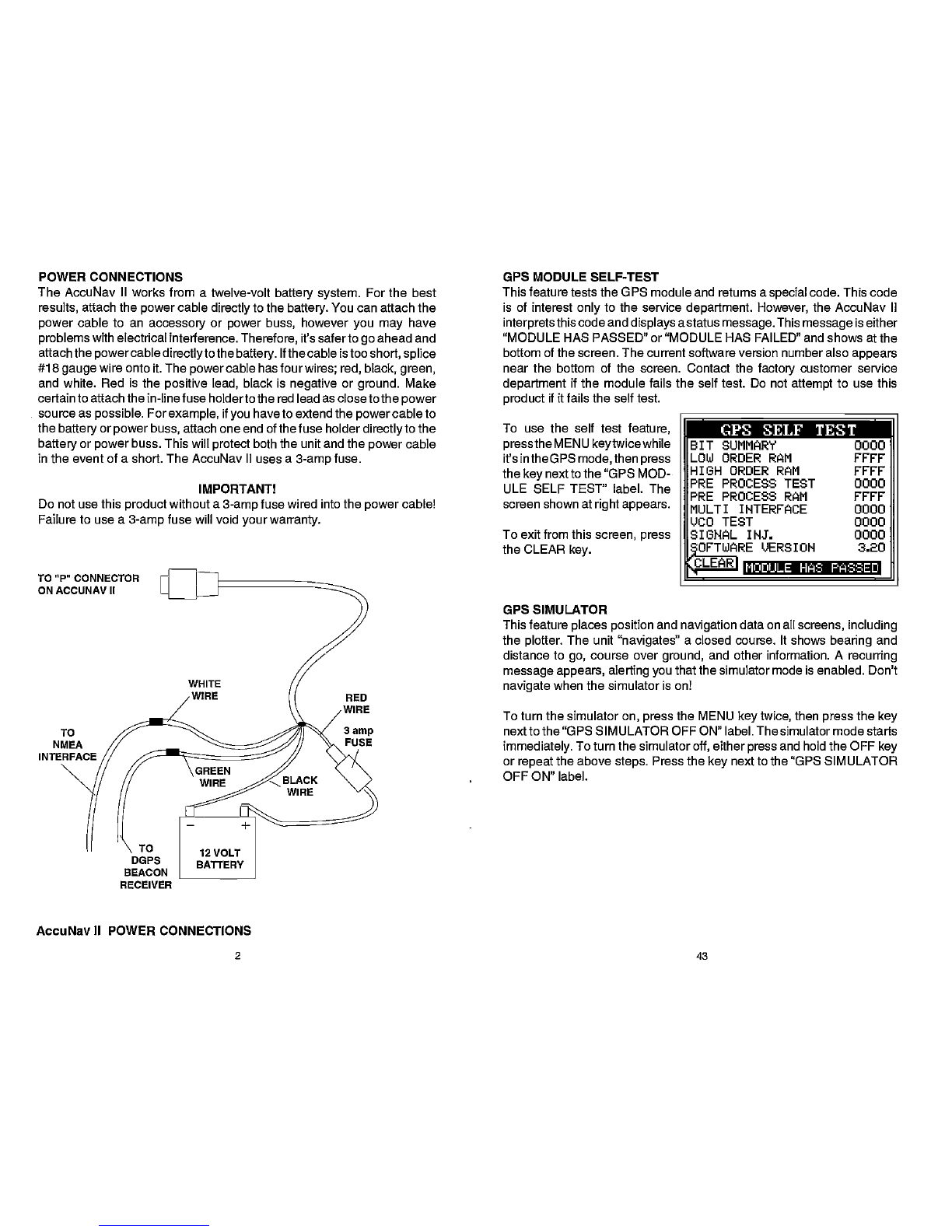
is the difference between the
location shownonthe present
position display and the posi-
tionshown onthechart.
Usethe
right
andleftarrowkeys
to movethe black box to the
numberthatyou wishto
change
in thelatitude, then enterthe
numbers.
Usethe
upordown arrow keys
Position
Correction
flflr
flFsET:NIooOO.oOO
MOO'
to
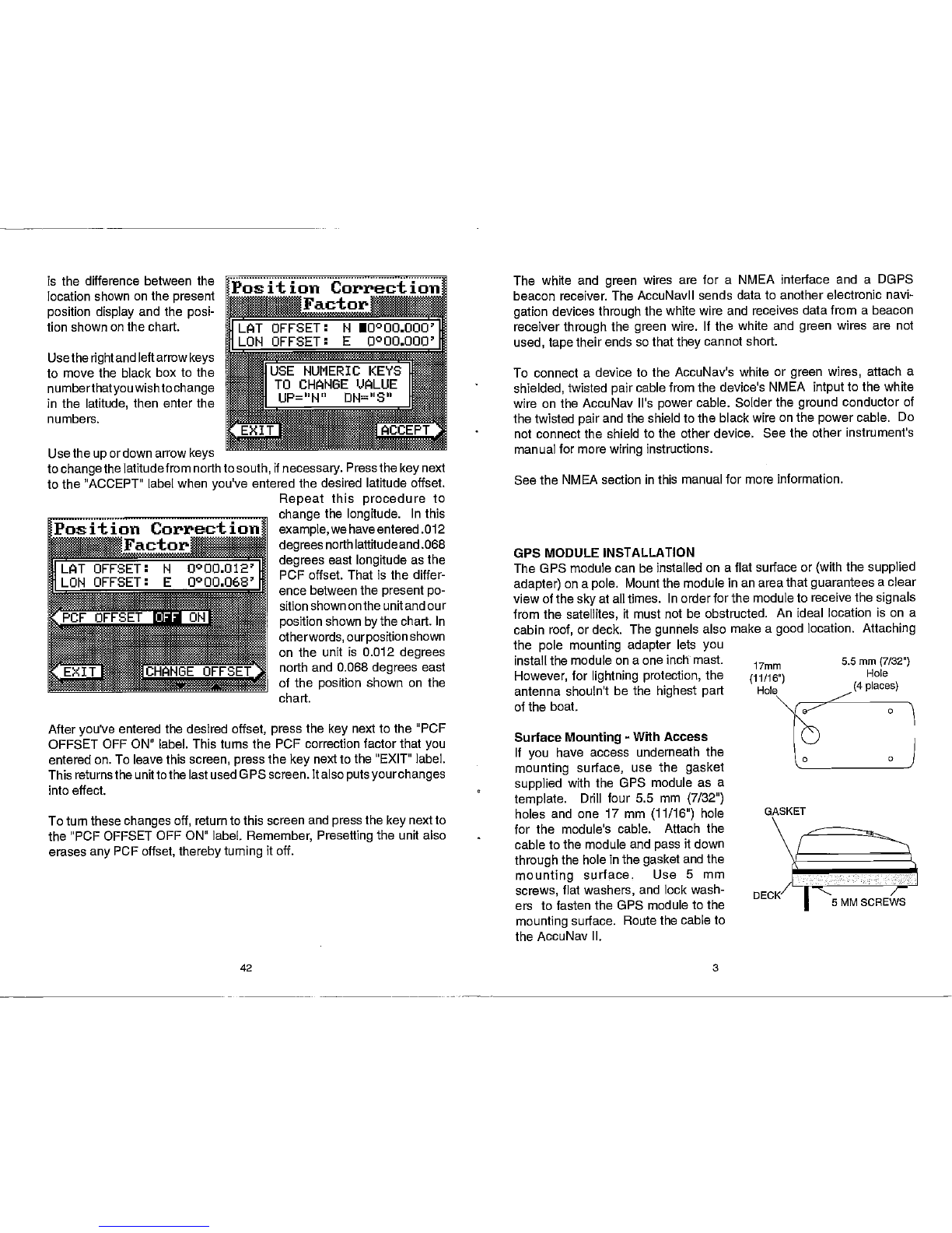
changethelatitudefromnorthto
south, if
necessary.Pressthe
keynext
tothe"ACCEPT" labelwhen
you've entered thedesired latitudeoffset.
Repeat this procedure to
thelongitude. In this
example,
wehaveentered.012
degreesnorthlattitude
and.068
degrees east longitudeasthe
PCFoffset. Thatisthediffer-
ence between thepresentpo-
sitionshownontheunitandour
positionshownby
thechart. In
otherwords,ourposition
shown
on the unit is 0.012 degrees
north and 0.068degrees east
of the position shown on the
Afteryou've entered thedesired offset, press the key nexttothe "PCF
OFFSET OFF ON" label. Thisturns the PCFcorrectionfactorthatyou
enteredon.Toleavethisscreen, pressthe
keynexttothe"EXIT"label.
ThisreturnstheunittothelastusedGPSscreen. Italsoputsyourchanges
into
effect.
Toturnthesechanges off, returntothisscreen and press
the
keynextto
the"PCF OFFSETOFFON" label. Remember, Presettingtheunitalso
erasesanyPCFoffset,therebyturning
itoff.
The white and green wires are for a NMEA interface and a DOPS
beacon receiver.TheAccuNavll sendsdatatoanotherelectronic
navi-
gation devicesthroughthewhite wire and receivesdatafromabeacon
receiverthrough the green wire. Ifthewhite and green wires are not
used, tape
theirends sothat
theycannot short.
To connect adevice to the AccuNav's white or green wires, attach a
shielded, twisted pair
cable
fromthedevice's NMEA intput tothewhite
wireon theAccuNav It'spowercable.Solder the ground conductor of
thetwisted pair
and theshieldtotheblack wire onthe
power
cable. Do
notconnect theshield totheotherdevice. Seetheotherinstrument's
manual formore wiring instructions.
SeetheNMEA section inthismanual formoreinformation.
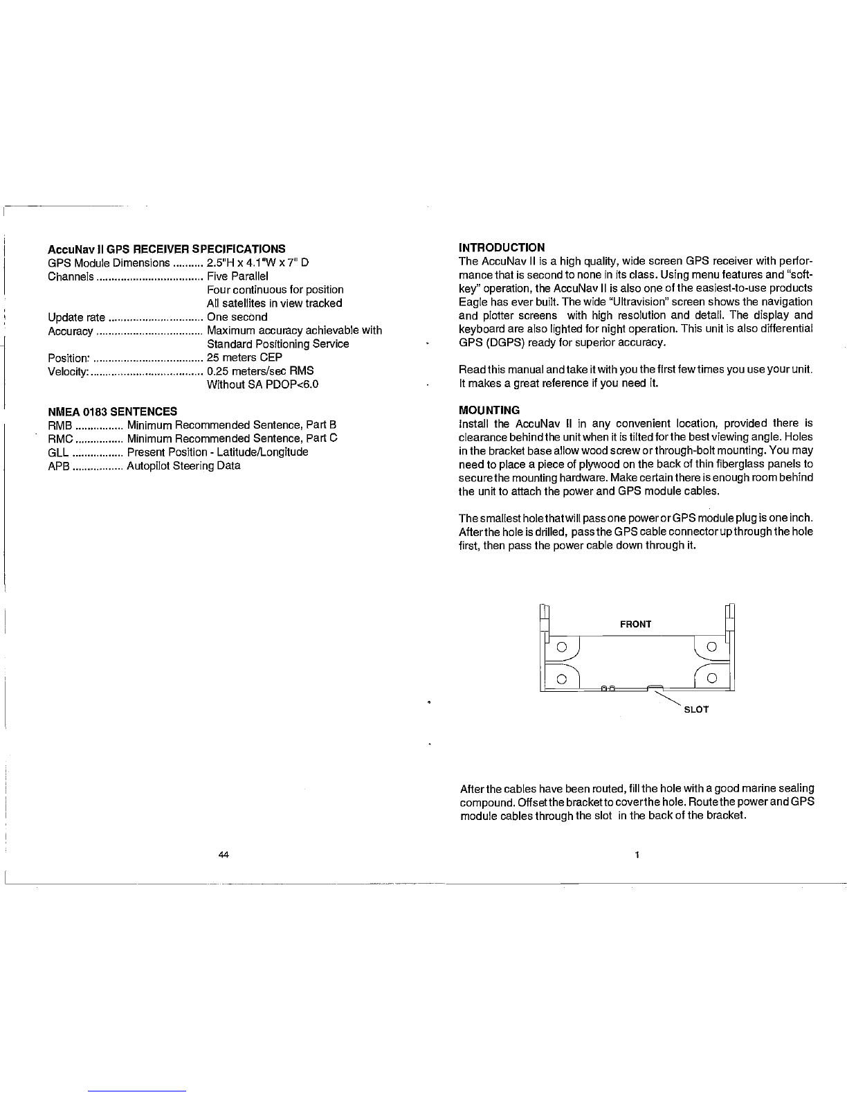
GPSMODULE INSTALLATION
TheGPSmodule canbeinstalledonaflatsurface or(with thesupplied
adapter) onapole. Mountthemodule in anareathatguaranteesaclear
viewofthe
sky
atalltimes. Inorderforthemodule toreceivethe
signals
fromthesatellites, it must notbe obstructed. An ideal location is on a
cabinroof, ordeck. Thegunhels also makeagood location. Attaching
the pole mounting adapter lets you
installthemodule onaoneinch mast. 17mm
However, forlightning protection, the (11/16")
antenna shoutn't be the highest part
oftheboat.
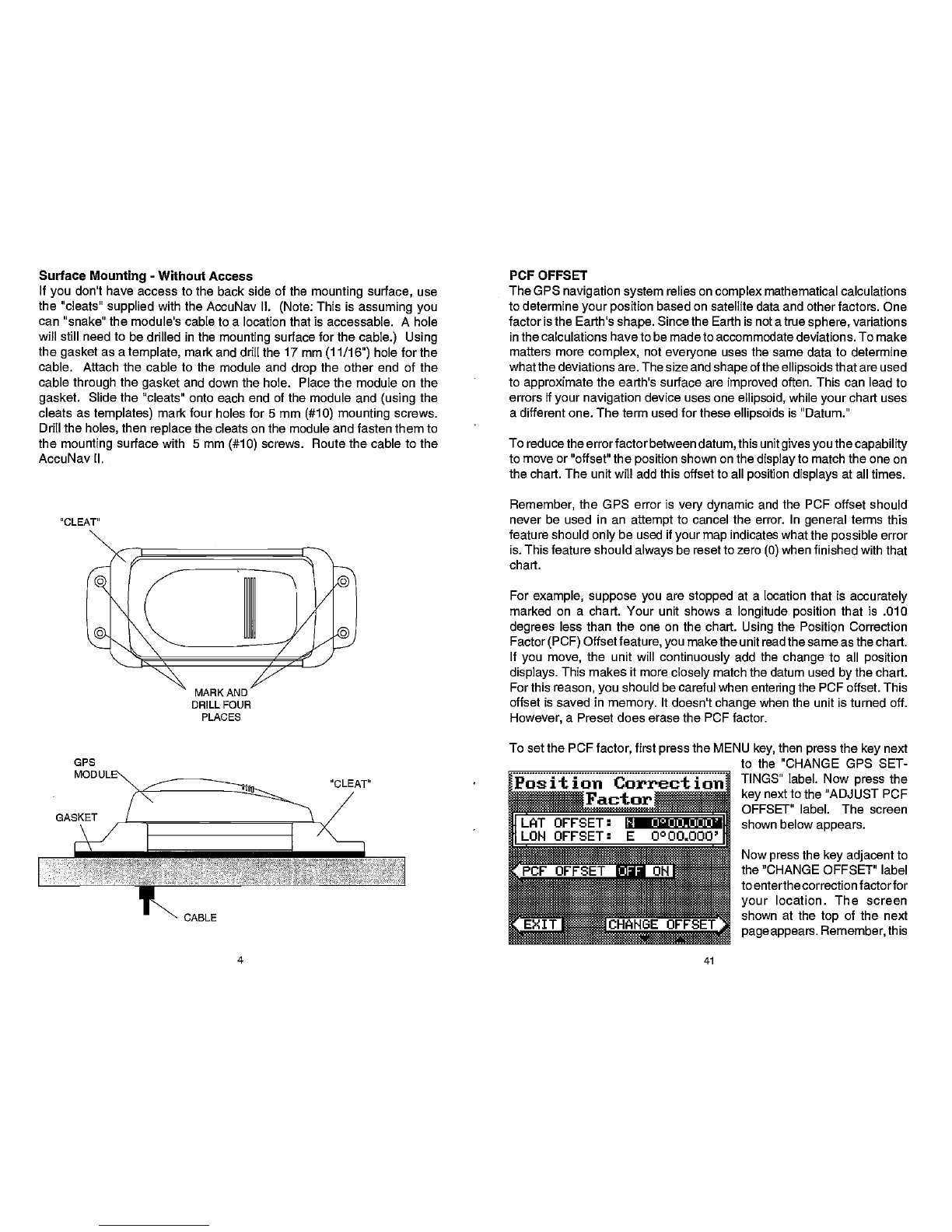
SurfaceMounting-WithAccess
If you have access underneath the
mounting surface, use the gasket
supplied with theOPS module as a
template. Drill four 5.5 mm (7/32")
holes and one 17 mm (11/16") hole
for the module's cable. Attach the
cabletothemodule and passitdown
through
thehole inthe
gasketandthe
mounting surface. Use 5 mm
screws, flatwashers, and lockwash-
ers tofasten theOPSmodule tothe
mountingsurface. Routethecableto
theAccuNavII.
42 3
IUSE
NUMERIC KEYS
TO CHANGE VALUE
*I
UP="N" DH="S"
Position CorrjoJ
Factor
chart.
5.5mm (7/32")
Hole
(4 places)
GASKET
5MM SCREWS
PDF compression, OCR, web-optimization with CVISION's PdfCompressor