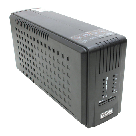
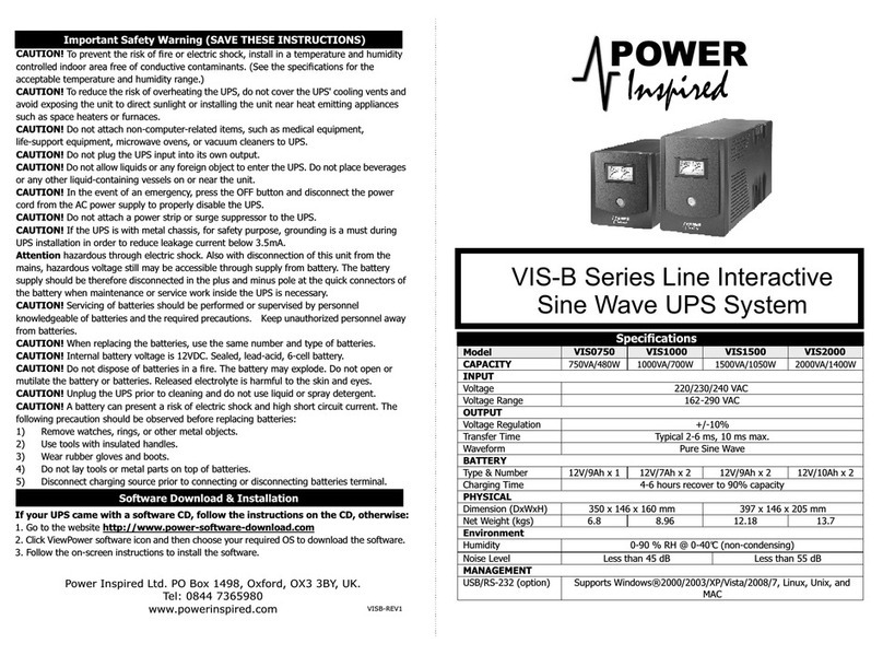
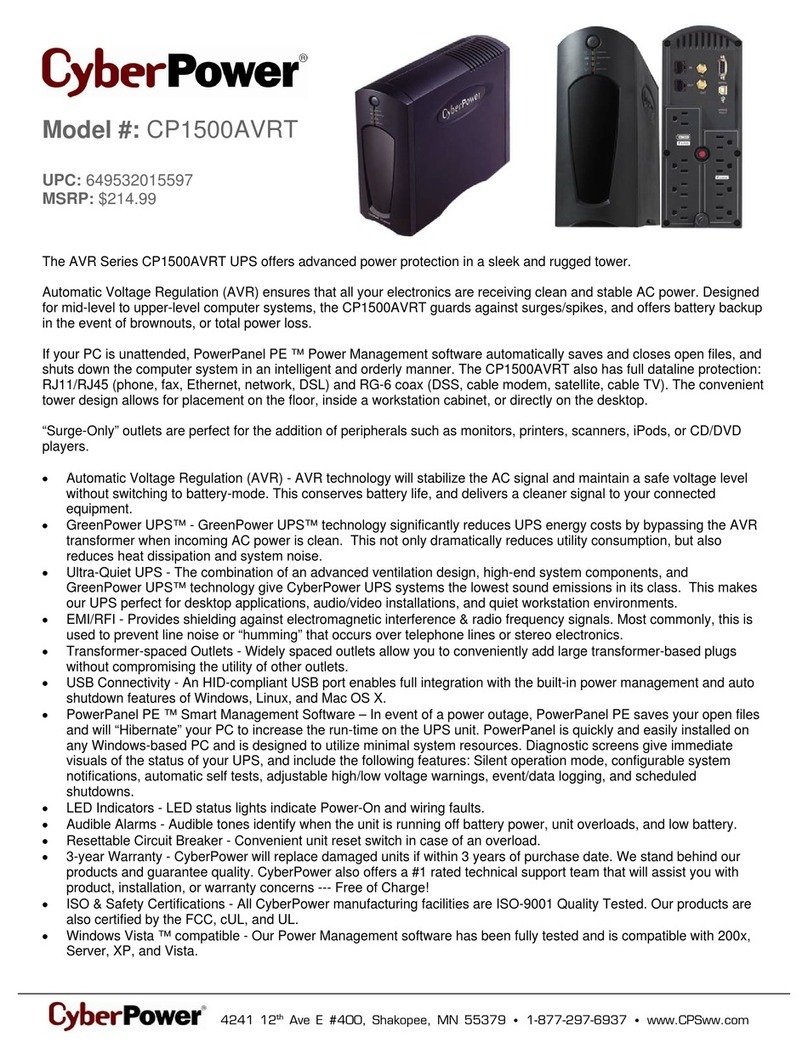
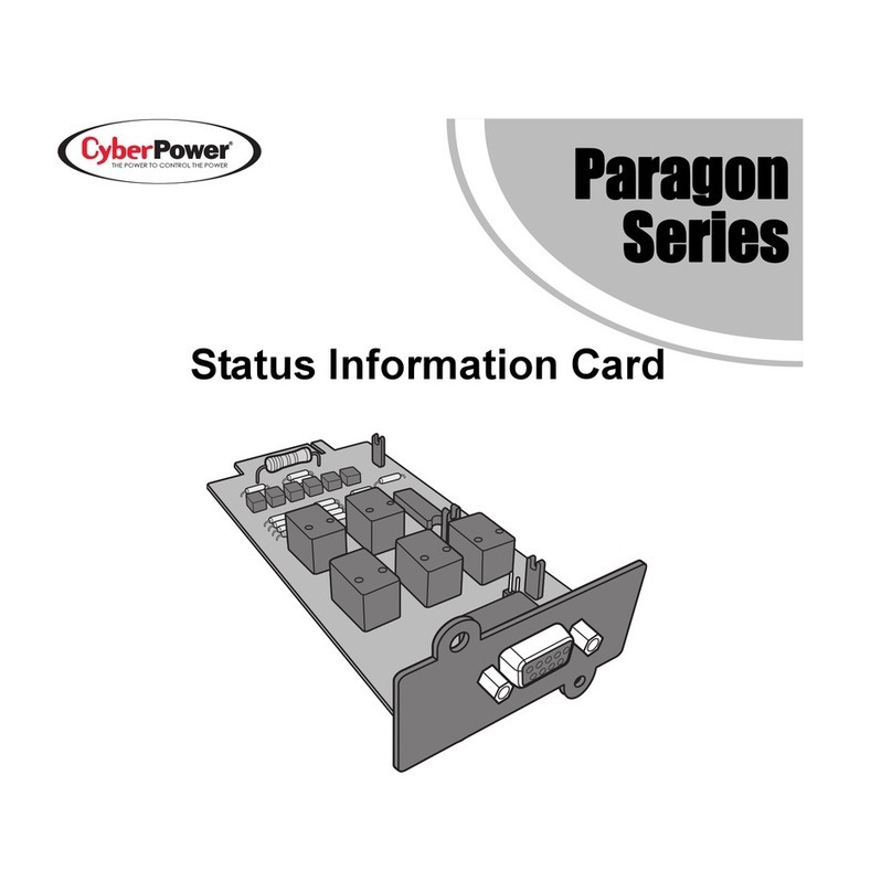
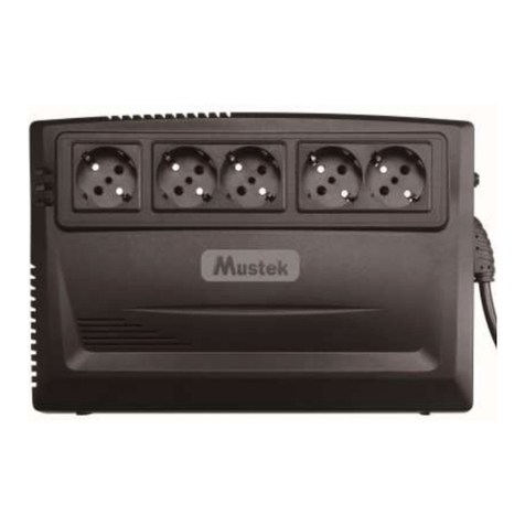
E&C Cheerups 600 Specifications

Line Interactive UPS
Cheerups
Cheerups
Cheerups
he sC erup
he sC erup
An ISO 9001:2008 Company
Installation and Operation Manual

Package Contents
Page 2
You should have received the following items inside of package:
- UPS Unit
- Installation and Operation Manual
- Communication cable (only for the model with USB/RS-232 port)
Product Overview
Front View:
RS-232
RS-232
USB
USB IN OUT
1
1
7
34
2
5
6
5
4
3
2
8
5
600 Model
w / RS-232
600 Model
w / USB
1000 Model
1
2
3
4
5
Output receptacle
AC input
RS-232 port (option)
USB port (option)
Circuit breaker (option)
6
7
8
RJ-11 port
RJ-45 port
RJ-11 or RJ-45 selections
Back View:
1
2
Power switch
UPS status LED
AC mode : green light
Battery mode : green flashing
Power switch
Fault LED : red light
Battery mode LED : yellow light
AC mode LED : green light
Installation and Operation Manual 1.0

NOTE: Before installation, please inspect the unit. Be sure that
nothing inside the package is damaged.
Placement & Storage Conditions
Install the UPS in a protected area that is free of excessive dust and adequate air
flow. Please place the UPS away from other units at least 20cm to avoid interference.
Do NOT operate the UPS where the temperature and humidity is outside the specific
limits. (Please check the specs for limitations.)
Installation & Initial Startup
Connect to Utility and Charging
Plug in the AC input cord to the wall outlet. For
the best results, suggest to charge the battery
at least 6 hours before initial use.
The unit charges its battery while connecting to
the utility. 6 hours
20 cm 20 cm
Connect Modem/Phone or Network for Surge Protection
(Only for the model with RJ-11/RJ-45
Connect a single modem/phone line into surge-protected “IN” outlet on the back panel
of the UPS unit. Connect from “OUT” outlet to the computer with phone line cable.
Connect Communication Cable (Only for the model with USB/RS-232 port)
To allow for unattended UPS shutdown/start-up and status monitoring, connect the
communication cable one end to the USB/RS-232 port and the other to the
communication port of your PC. With the monitoring software installed, you can
schedule UPS shutdown/start-up and monitor UPS status through PC.
CAUTION: NEVER connect a laser printer or scanner to
the UPS unit. This may cause the damage of the unit.
Turn On/Off the Unit
Turn ON the UPS unit by pressing the power switch. Turn OFF the UPS unit by pressing
again the power switch.
Cold Start Function
When the UPS is off and there is no power utility, it’s still possible to cold start the UPS
unit to power the loads.
3
Page 3
Installation and Operation Manual 1.0

Important safety Warning
(SAVE THESE INSTRUCTIONS)
CAUTION! To prevent the risk of fire or electric shock, install in a
temperature and humidity controlled indoor area free of conductive
contaminants. (See the specifications for the acceptable temperature and
humidity range.)
CAUTION! To reduce the risk of overheating the UPS, do not cover the UPS’
cooling vents and avoid exposing the unit to direct sunlight or installing the
unit near heat emitting appliances such as space heaters or furnaces.
CAUTION! Do not attach non-computer-related items, such as medical
equipment, life-support equipment, microwave ovens, or vacuum cleaners to
UPS.
CAUTION! Do not plug the UPS input into its own output.
CAUTION! Do not allow liquids or any foreign object to enter the UPS. Do
not place beverages or any other liquid-containing vessels on or near the unit.
CAUTION! In the event of an emergency, press the OFF button and
disconnect the power cord from the AC power supply to properly disable the
UPS.
CAUTION! Do not attach a power strip or surge suppressor to the UPS.
CAUTION! If the UPS is with metal chassis, for safety purpose, grounding is
a must during UPS installation in order to reduce leakage current below 3.5A.
Attention hazardous through electric shock. Also with disconnection of this
unit from the mains, hazardous voltage still may be accessible through supply
from battery. The battery supply should be therefore disconnected in the plus
and minus pole at the quick connectors of the battery when maintenance or
service work inside the UPS is necessary.
CAUTION! Servicing of batteries should be performed or supervised by
personnel knowledgeable of batteries and the required precautions. Keep
unauthorized personnel away from batteries.
CAUTION! When replacing the batteries, use the same number and type of
batteries.
CAUTION! Internal battery voltage is 12Vdc. Sealed, lead-acid, 6-cell battery.
CAUTION! Do not dispose of batteries in a fire. The battery may explode. Do
not open or mutilate the battery or batteries. Released electrolyte is harmful
to the skin and eyes.
CAUTION! Unplug the UPS prior to cleaning and do not use liquid or spray
detergent.
CAUTION! A battery can present a risk of electric shock and high short
circuit current. The following precaution should be observed before replacing
batteries:
1) Remove watches, rings, or other metal objects.
2) Use tools with insulated handles.
3) Wear rubber gloves and boots.
4) Do not lay tools or metal parts on top of batteries.
5) Disconnect charging source prior to connecting or disconnecting batteries
terminal.
4
Page 4
Installation and Operation Manual 1.0

Problem Probable Cause Solution
Low battery
Battery fault
UPS is not turned on
UPS is overload
UPS is overload Remove some critical load
Battery voltage is too low
Power cord is loose
No LED display on
the front panel
Charge the UPS at least 8
hours
Replace the battery with the
same type of battery
Press te power switch again
to turn on the UPS
Alarm continuously
sounds when the
mains in normal
Remove some loads first.
Before reconnecting
equipment, please verity
that the load matches the
UPS capability specified in
the specs
When power fails,
backup time is
shorten
Charge te UPS at least 8
hours
Battery defect. It might be
due to high temperature
operation environment, or
improper operation to
battery
Replace the battery with the
same type of battery
The mains is normal
but LED is flashing
Reconnect the power cord
properly
Trouble Shooting
6
Use the table below to solve minor problems.
Software Download & Installation
(Only for the model with communication port)
5
Please follow steps below to download and install monitoring software:
1. Go to the website http://www.power-software-download.com
2. Click viewPower software icon and then choose your required Operating System to
download the software
3. Follow the on-screen instructions to install the software
4. When your computer restarts, the monitoring software will appear as an orange
plug icon located in the system tray, near the clock.
Page 5
Installation and Operation Manual 1.0

Specification
7
Page 6
Installation and Operation Manual 1.0

Page 7
Warranty Introduction:
Electronics & Controls Power Systems Pvt. Ltd ("E&C") warrants that its products are free from
defects in material and workmanship. During the warranty period, if the product fails under normal
use in the recommended environment due to improper workmanship or materials, E&C will repair or
replace the product with a comparable product.
This warranty is valid for a specific period from the date of purchase for which Proof of date of
purchase is required. E&C Engineer will inspect the product and make a decision regarding repair or
replacement. E&C reserves the right to provide a functional equivalent, or refurbished replacement
product.
Limitation:
This warranty does not apply to product failure due to accident, abuse, mishandling, improper
installation, alteration, acts of nature, improper usage, problems due to electrical power and product
service and repaired by anyone other than E&C. Burnt components are not covered under this
warranty.
Reduced Battery life or backup time due to improper or lack of charging of the battery is not covered
under this warranty.
In addition to the above, opening or tampering with the product casing, or any Physical damage,
abuse or alteration to the product's surface, including all Warranty, Quality stickers, Product serial or
electronic number will also void the Warranty.
E&C will not be liable for damages resulting from a third party device that causes the Product to fail.
E&C shall in no event be liable for any consequential, indirect, or incidental damages, lost profits, lost
business, investments, lost goodwill, or interference with business relationships as a result of lost
data.
This warranty extends only to the original purchase and is non-transferable.
Warranty Period:
To Obtain warranty service, customer must provide original proof of purchase or
invoice. In addition, the warranty card should be sent to the manufacturer at the address provided on
the Warranty Card.
Product : UPS (Uninterrupted Power Supply)
Service Type : Onsite / Carry-In (Service Center)
Period : 1 Year (for UPS & Battery)
Warranty Procedure:
a. To Log a call to the E&C Centre for a Carry-In or an on-site warranty service, you must contact
Nearest Service Center or our customer care number 080-2837 7120/21. Service Centers' list is
enclosed herewith.
b. Invoice copy issued by the Retailer/Reseller to the End user containing product serial number and
date of purchase is required to validate the warranty period.
c. After validating the warranty status, service centers will carry out ONSITE repair / replacement.
Onsite service will be provided by the nearest existing service center.
d. All Customer calls will be responded within 48 Hours of call logging, from the nearest service center
available.
e. DOA (Dead on Arrival) units will be replaced if failed within 7 days from the date of purchase and
should be supported by Reseller/Retailer invoice to the customer.
f. This Warranty is only applicable for products bought and sold in India.
* Terms and Conditions are subject to change without notice.
NOTWITHSTANDING ANYTHING ELSE IN THIS POLICY OR OTHERWISE, WD WILL NOT BE LIABLE WITH RESPECT TO
THE PRODUCTS UNDER ANY CONTRACT, NEGLIGENCE, STRICT LIABILITY OR OTHER LEGAL OR EQUITABLE THEORY
(I) FOR ANY AMOUNT IN EXCESS OF THE PURCHASE PRICE FOR THE DEFECTIVE PRODUCT OR (II) FOR ANY GENERAL,
CONSEQUENTIAL, PUNITIVE, INCIDENTAL OR SPECIAL DAMAGES. THESE INCLUDE LOSS OF RECORDED DATA,
INTERRUPTION OF USE, THE COST OF RECOVERY OF LOST DATA, LOST PROFITS AND THE COST OF THE
INSTALLATION OR REMOVAL OF ANY PRODUCTS, THE INSTALLATION OF REPLACEMENT PRODUCTS, AND ANY
INSPECTION, TESTING, OR REDESIGN CAUSED BY ANY DEFECT OR BY THE REPAIR OR REPLACEMENT OF PRODUCTS
ARISING FROM A DEFECT IN ANY PRODUCT.
Warranty Policy
8
Installation and Operation Manual 1.0

Contact Information
Head Office
29/A, 2nd Phase, Peenya Industrial Area, Bangalore - 560 058, India.
Tel No : +91-80-28371974 / 28379401, Fax No : +91-80-28391587
For sales enquiries contact : sales@eandcpower.com
Regional Sales Offices
wAhmedabad wBangalore wChandigarh wChennai wCochin wHyderabad
wIndore wJaipur wKolkata wLucknow wMumbai wNew Delhi
Service Locations
•Agra
•Ahmedabad
•Aurangabad
•Agartala
•Bangalore
•Baroda
•Bhopal
•Bhubaneshwar
•Chandigarh
•Chennai
•Cochin
•Coimbatore
•Calicut
•Dehradun
•Guwahati
•Gwalior
•Hubli
•Hyderabad
•Indore
•Jabalpur
•Jaipur
•Jammu
•Kanpur
•Kolkata
•Kottayam
•Ludhiana
•Lucknow
•
•Madurai
Meerut
•Mumbai
•Munnar
•Mangalore
•Mysore
•Nagpur
•New Delhi
•Ongole
•Palakkad
•Patna
•Pondicherry
•Pune
•Raipur
•Ranchi
•Rajamundry
•Salem
•Srinagar
•Tirupati
•Trichy
•Tirunelveli
•Trivandrum
•Udaipur
•Vizag
•Vijayawada
•Varanasi
Works
A-95(BIS), PIPDIC Industrial Area, Mettupalayam, Pondicherry - 605 009,
India. Tel No : +91-413-2277241, Fax No : +91-413-4302241
For Service, Call our Helpline Tel No: 91-80-28397120 / 28397121
www.eandcpower.com
Page 8
vOn-line UPS
v
Inverters
vServo Controlled Voltage
Stabilizer
vEnergy Saver
vIsolation Transformers
vBatteries
vBattery Chargers
vIntelligent Power Module
vRemote Monitoring Solutions
Our other products
This manual suits for next models
1
Table of contents
