Set the 110/220 volt select switch for your power requirement. The supplied power
cord plugs into the IEC receptacle. The receptacle also contains a fuse drawer. Two
(2) fuses are located in this compartment. For 110 VAC +/- 10% operation the unit is
equipped with slow blow 320ma Fuses. For 220 VAC +/- 10% operation the unit is
equipped with slow blow 160ma Fuses. Additionally, you will find the Master and
Subchannel female DB-15 connectors.
2.3 CLOCKING MODES
Clocking may be set as Master Channel (Set to DTE) or Channel 4 (Set to DTE) from
the attached DCE. Internal Timing will facilitate user defined operational speeds from
48Khz to 256Khz. Fallback Timing may also be used when the Master Port is connected
to a Front End Processor (FEP) or other DTE device. In this mode, connect Port 1 to the
main clock source. If Port 1 clock fails, fallback to Port 2 clock source will occur. If Port
2 clock source fails, fallback to internal clock will occur. If Port 1 or 2 clock returns, the
DMM-X21 will fall forward to the active DCE clock source with Port 1 having the highest
priority.
A Green LED illuminates when AC Power has been applied. Two adjacent Green LEDs
illuminate in union with individual Green subchannel port activity LEDs and identify
Transmit and Receive data transmissions. Yellow LEDs provide the user with a visual
indication of a streaming DTE (ref. 2.6) Positive latching switches are provided for each
DTE port for isolating or removing a streaming terminal. Each DTE port has its own
switch and operates independently. To disable a subchannel, simply push the switch.
A channel is disabled when the switch is in the outer most position.
2.2 REAR PANEL CONNECTORS AND FUSES
CHAPTER 2 - BASIC OPERATION
2.1 FRONT PANEL INDICATORS AND SWITCHES
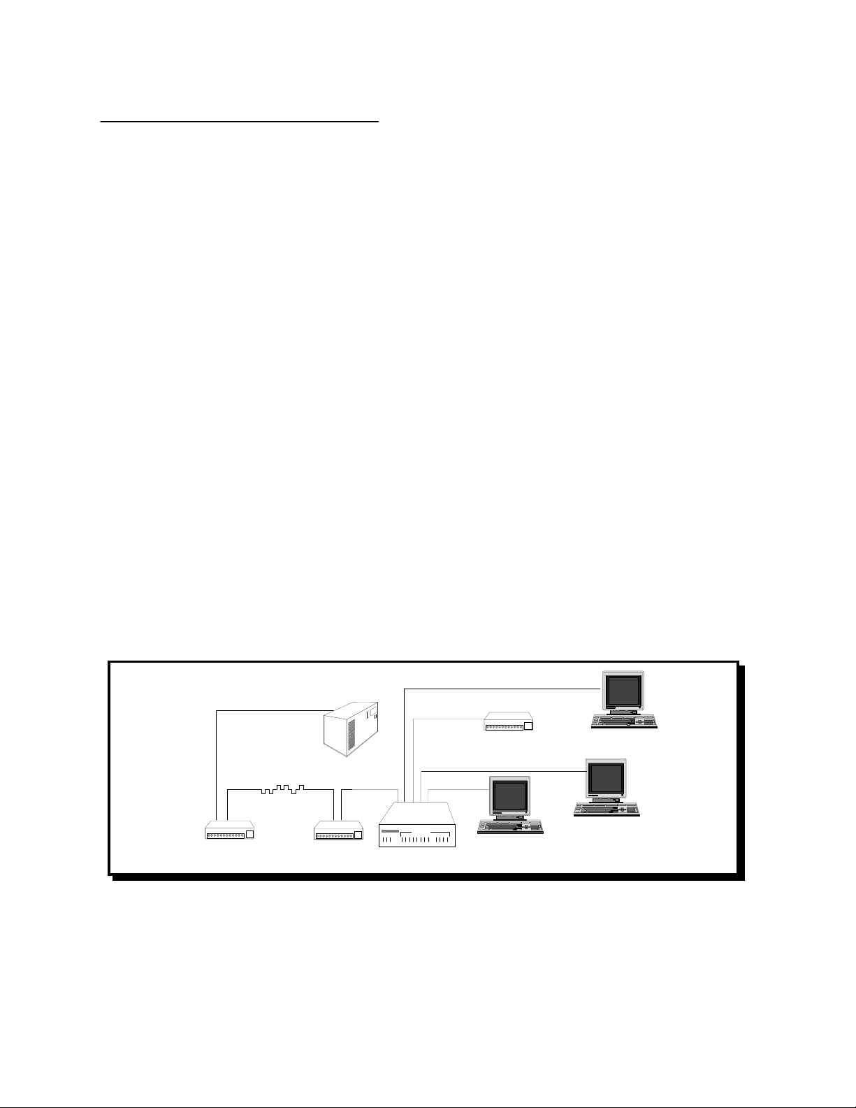
1.2 THEORY OF OPERATION
The DMM-X21 allows up to four DCEs or DTEs to share one DCE or DTE
communications link. In a broadcast, polled or contention environment, the typical
Polled Network DMM-X21 operation is as follows:
Data arriving at the DMM-X21's master port is continually broadcast to all subchannel
ports. When one of the DCE or DTE devices answers a poll from the host site, that
device will raise Control (C) or Indicate (I). When (C) is raised, the DMM-X21 will lock
on to that port and allow that DTE device to talk to the modem link. The DMM-X21 will
remain locked onto that port until (C) is dropped. After (C) has dropped, the DMM-X21
will automatically begin scanning the ports until another port raises (C) or (I).
East Coast Datacom, Inc. DMM-X21 OPERATIONS MANUAL
Page 3