EASTMAN Kodak X-Omat 180 LP Setup guide

© Eastman Kodak Company
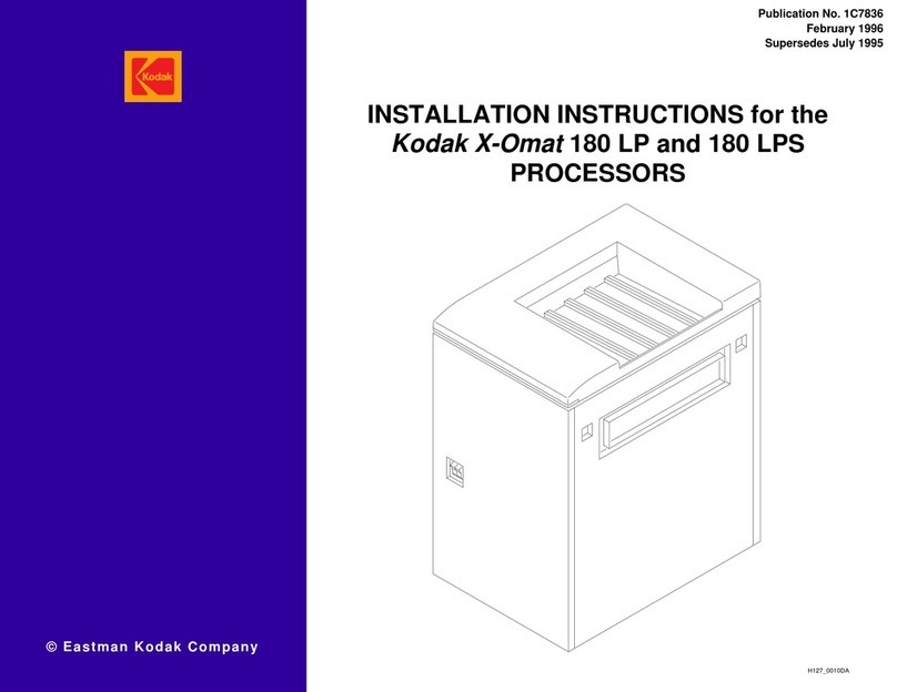
Publication No. 1C7839
July 1995
DIAGNOSTICS for the
Kodak X-Omat
180 LP and 180 LPS
PROCESSORS
H127_0010DA

2 July 1995 – 1C7839
PLEASE NOTE The information contained herein is based on the experience and knowledge relating to the
subject matter gained by Eastman Kodak Company prior to publication.
No patent license is granted by this information.
Eastman Kodak Company reserves the right to change this information without notice, and
makes no warranty, express or implied, with respect to this information. Kodak shall not be liable
for any loss or damage, including consequential or special damages, resulting from any use of
this information, even if loss or damage is caused by Kodak’s negligence or other fault.
This equipment includes parts and assemblies sensitive to damage from electrostatic
discharge. Use caution to prevent damage during all service procedures.
Description Page
Table of Contents
Introduction and Definitions . . . . . . . . . . . . . . . . . . . . . . . . . . . . . . . . . . . . . . . . . . . . . . . . 3
Introduction. . . . . . . . . . . . . . . . . . . . . . . . . . . . . . . . . . . . . . . . . . . . . . . . . . . . . 3
Fatal Errors. . . . . . . . . . . . . . . . . . . . . . . . . . . . . . . . . . . . . . . . . . . . . . . . . . . . . 3
Non-fatal Errors . . . . . . . . . . . . . . . . . . . . . . . . . . . . . . . . . . . . . . . . . . . . . . . . . 3
Warning Errors. . . . . . . . . . . . . . . . . . . . . . . . . . . . . . . . . . . . . . . . . . . . . . . . . . 3
Error and Warning Codes . . . . . . . . . . . . . . . . . . . . . . . . . . . . . . . . . . . . . . . . . . . . . . . . . 4
Fatal Errors . . . . . . . . . . . . . . . . . . . . . . . . . . . . . . . . . . . . . . . . . . . . . . . . . . . . . . . . 4
Non-fatal Errors . . . . . . . . . . . . . . . . . . . . . . . . . . . . . . . . . . . . . . . . . . . . . . . . . . . . . 5
Warnings . . . . . . . . . . . . . . . . . . . . . . . . . . . . . . . . . . . . . . . . . . . . . . . . . . . . . . . . . . 12
Mechanical Diagnostics . . . . . . . . . . . . . . . . . . . . . . . . . . . . . . . . . . . . . . . . . . . . . . . . . . 13
Problem — Transport Malfunctions . . . . . . . . . . . . . . . . . . . . . . . . . . . . . . . . . . . . . 13
Rack and Crossover Remedies . . . . . . . . . . . . . . . . . . . . . . . . . . . . . . . . . . . . . 13
Roller Remedies . . . . . . . . . . . . . . . . . . . . . . . . . . . . . . . . . . . . . . . . . . . . . . . . 13
Dryer Remedies . . . . . . . . . . . . . . . . . . . . . . . . . . . . . . . . . . . . . . . . . . . . . . . . 13
Miscellaneous Remedies . . . . . . . . . . . . . . . . . . . . . . . . . . . . . . . . . . . . . . . . . 13
Problem — Surface Artifacts or Abnormal Densities . . . . . . . . . . . . . . . . . . . . . . . . 14
Replenishment Remedies . . . . . . . . . . . . . . . . . . . . . . . . . . . . . . . . . . . . . . . . . 14
Recirculation Remedies . . . . . . . . . . . . . . . . . . . . . . . . . . . . . . . . . . . . . . . . . . 14
Rack and Crossover Remedies . . . . . . . . . . . . . . . . . . . . . . . . . . . . . . . . . . . . . 14
Roller Remedies . . . . . . . . . . . . . . . . . . . . . . . . . . . . . . . . . . . . . . . . . . . . . . . . 14
Dryer Remedies . . . . . . . . . . . . . . . . . . . . . . . . . . . . . . . . . . . . . . . . . . . . . . . . 15
Miscellaneous Remedies . . . . . . . . . . . . . . . . . . . . . . . . . . . . . . . . . . . . . . . . . 15
Problem — Wet Films . . . . . . . . . . . . . . . . . . . . . . . . . . . . . . . . . . . . . . . . . . . . . . . 16
Replenishment Remedies . . . . . . . . . . . . . . . . . . . . . . . . . . . . . . . . . . . . . . . . . 16
Recirculation Remedies . . . . . . . . . . . . . . . . . . . . . . . . . . . . . . . . . . . . . . . . . . 16
Dryer Remedies . . . . . . . . . . . . . . . . . . . . . . . . . . . . . . . . . . . . . . . . . . . . . . . . 16
Wash Water Remedies . . . . . . . . . . . . . . . . . . . . . . . . . . . . . . . . . . . . . . . . . . . 16
Problem — Solution Levels . . . . . . . . . . . . . . . . . . . . . . . . . . . . . . . . . . . . . . . . . . . 17
Replenishment Remedies . . . . . . . . . . . . . . . . . . . . . . . . . . . . . . . . . . . . . . . . . 17
Publication History . . . . . . . . . . . . . . . . . . . . . . . . . . . . . . . . . . . . . . . . . . . . . . . . . . . . . . 19

Introduction and Definitions
1C7839 – July 1995 3
Section 1: Introduction and Definitions
Introduction• The 500 CIRCUIT BOARD monitors the operation of the Processor and continuously checks for
errors. When an error occurs, an error code displays on the DISPLAY PANEL of the PRINTER.
• Error codes appear in order of priority.
• More than one error code can occur at one time.
• The lower the error code number, the higher its priority.
• When 2 or more errors occur at the same time, only the highest priority error code appears on the
display panel.
• When the higher priority error/warning code is corrected, the next priority error/warning code
appears on the display panel.
• In addition, all errors are stored in an error log on the 500 CIRCUIT BOARD. This error log,
accessable with the portable computer and appropriate software, indicates how many times each
error has occured.
• There are 3 types of error codes: Fatal, Non-Fatal, and Warning.
Note
When errors occur, certain components may be disabled by the microprocessor. Use the portable
computer and diagnostic tests to help troubleshoot the components.
Fatal Errors
A Fatal Error is any error that can cause a hazardous situation to develop if the processor is allowed to
continue to operate. The user cannot correct the error. The printer will not send film to the processor.
Move the MAIN CIRCUIT BREAKER CB1 to the “O” position and call for service.
Non-fatal Errors
A Non-Fatal Error is any error that in most cases cannot be corrected by the operator. The printer will
not send film to the processor. The operator should call for service.
Warning Errors
A Warning Error is any error that can be corrected by the operator. The operator can override some
errors, such as an E132 and an E134, to allow the printer to send film.
The processor can continue to operate. The error is a temporary condition or one which the operator
can correct. Image quality may be reduced.

DIAGNOSTICS
4 July 1995 – 1C7839
Section 2: Error and Warning Codes
Fatal Errors
Error
Code Error
Description Possible
Malfunction Action
E001 500 Circuit Board 500 CIRCUIT BOARD Install a new 500 CIRCUIT BOARD.
Corrupted software on the
CIRCUIT BOARD Download new software or install a new
U19.
E002 Dryer Over Temperature
Greater than 74˚C
(165˚F)
DRYER THERMISTOR
CONNECTORS are loose,
worn, or corroded.
• Clean or repair the CONNECTORS.
• Tighten the CONNECTORS.
DRYER THERMISTOR
• is open or shorted
• the resistance is not
correct
• Check that the resistance at 25˚C (77˚F)
is approximately 10K ohm.
• Install a new DRYER THERMISTOR.
SOLID STATE RELAY U3
(controls the DRYER
HEATER)
• Check for correct operation of SOLID
STATE RELAY U3.
• Install a new RELAY U3.
E005 Loss of Dryer Air Flow or
Open Dryer
Overtemperature
Thermostat
The DRYER HEATER and BLOWER will be disabled when this error exists.
AIR FLOW SWITCH Install a new AIR FLOW SWITCH.
DRYER OVERTEMP
THERMOSTAT • Reset or install a new
OVERTEMPERATURE
THERMOSTAT, if necessary. (If
OVERTEMPERATURETHERMOSTAT
opens again, determine the cause of the
overtemperature condition. See E002.)
DRYER BLOWER not
operating Check and replace if necessary:
• FUSE F1
• DRYER BLOWER
500 CIRCUIT BOARD
• Malfunction of RELAY
K502
Install a new 500 CIRCUIT BOARD.

Error and Warning Codes
1C7839 – July 1995 5
Non-fatal Errors
Error
Code Error
Description Possible
Malfunction Action
E032 Developer Tank Fill This error will occur if the DEVELOPER TANK does not fill in 4 minutes
in normal operation and 15 minutes in the Tank Fill Mode. This error will
occur if the DEVELOPER TANK is empty and the Tank Fill mode is not
selected.
This error can also occur during initial setup when the TANKS of the
processor are filled with water. To prevent the error, add 8 fluid ounces
of developer to the DEVELOPER TANK before filling the Processor with
water. Using the diagnostics, energize the RECIRCULATION PUMP to
circulate the developer and remove any air bubbles.
LEVEL PROBES and
CONNECTORS • Clean LEVEL PROBES.
• Clean and check connections for the
LEVEL PROBE CONNECTORS.
Solution level is low in the
REPLENISHER TANK. Mix new developer solution.
REPLENISHMENT HOSE
has an air bubble, kink or
other obstruction.
Remove any HOSE obstructions between
the REPLENISHER TANK and the
REPLENISHMENT PUMP.
DEVELOPER DRAIN
VALVE is open. Close the DEVELOPER DRAIN VALVE.
SOLID STATE RELAY U4
(Controls the DEVELOPER
REPLENISHMENT PUMP.)
• Check for correct operation of SOLID
STATE RELAY U4.
• If necessary, install a new SOLID
STATE RELAY U4.
DEVELOPER
REPLENISHMENT PUMP • Check FUSE F1
• Check for correct operation of MOTOR
B3.
• Ifnecessary, install a new DEVELOPER
REPLENISHMENT PUMP.
POPPET VALVES in the
DEVELOPER
REPLENISHMENT PUMP
• Clean the POPPET VALVES.
• If necessary, install new POPPET
VALVES.
500 CIRCUIT BOARD
• Voltage at SOLID STATE
RELAY U4 PINS 3 and 4
is not
5 V DC during
replenishment.
• ACsideofRELAY K506B
is open during
replenishment.
• Malfunctionoflevelsense
circuit.
Install a new 500 CIRCUIT BOARD.

DIAGNOSTICS
6 July 1995 – 1C7839
Error
Code Error
Description Possible
Malfunction Action
E033 Fixer Tank Fill This error will occur if the FIXER TANK does not fill in 4 minutes in
normal operation and 15 minutes in the Tank Fill Mode. This error will
occur if the FIXER TANK is empty and the Tank Fill mode is not
selected.
This error can also occur during initial setup when the TANKS of the
Processor are filled with water. To prevent the error, add 8 fluid
ounces of fixer to the FIXER TANK before filling the Processor with
water. Use the diagnostics and the portable computer to operate the
RECIRCULATION PUMP. The PUMP will circulate the fixer and
remove any air bubbles.
LEVEL PROBES and
CONNECTORS • Clean LEVEL PROBES.
• Clean and check connections for the
LEVEL PROBE CONNECTORS.
Solution level is low in the
REPLENISHER TANK. Mix new fixer solution.
HOSE has an air bubble, kink
or other obstruction. Remove any HOSE obstructions
between the REPLENISHER TANK and
the REPLENISHMENT PUMP.
FIXER DRAIN VALVE is
open. Close the FIXER DRAIN VALVE.
SOLIDSTATERELAYU2that
controls the FIXER
REPLENISHMENT PUMP
• Checkfor correct operation of SOLID
STATE RELAY U2.
• If necessary, install a new SOLID
STATE RELAY U2.
FIXER REPLENISHMENT
PUMP • Check FUSE F1.
• Check for correct operation of
MOTOR B4.
• If necessary, install a new FIXER
REPLENISHMENT PUMP.
POPPET VALVES in the
FIXER REPLENISHMRNT
PUMP
• Clean the POPPET VALVES.
• Ifnecessary,newPOPPETVALVES.
500 CIRCUIT BOARD
• Voltage at SOLID STATE
RELAYU2PINS3and4is
not 5 V DC during
replenishment.
• AC side of RELAY K506A
is open during
replenishment.
• Malfunction of level sense
circuit.
Install a new 500 CIRCUIT BOARD.

Error and Warning Codes
1C7839 – July 1995 7
Error
Code Error
Description Possible
Malfunction Action
E034 Unable to Determine
Developer Temperature The DEVELOPER HEATER and DEVELOPER COOLING SOLENOID will
be disabled when this error exists.
DEVELOPER THERMISTOR
• is open or shorted
• The resistance is not
correct.
• Check that the resistance at 25˚C
(77˚F) is approximately 10K ohms.
• If necessary, install a new
DEVELOPER THERMISTOR.
DEVELOPER THERMISTOR
CONNECTORS are loose,
worn, or corroded.
• Clean or repair the CONNECTORS.
• Tighten the connections.
500 CIRCUIT BOARD
• Malfunction of the A/D
conversion.
• Precision RESISTOR test
fails.
Install a new 500 CIRCUIT BOARD.
Ambient temperature is below
15˚C (59˚F), causing the
developer to be below
measuring range of A/D
• Increase the ambient temperature.
• De-energize and then energize the
Processor to allow more time for
solutions to be heated before
measuring the temperature.
Temperature of developer is
above the measuring range of
A/D >66˚C (105˚F)
Determine the cause of developer over-
temperature. If necessary, change the
SOLID STATE RELAY U5.
See E037 for additional actions.
E035 Unable to Determine Fixer
Temperature The FIXER HEATER will be disabled when this error occurs.
(Moving DIP SWITCH 1
on the 500 CIRCUIT
BOARD to “ON” will
disable report of this error)
FIXER THERMISTOR
• is open or shorted
• The resistance is not
correct.
• Check that the resistance at 25˚C
(77˚F) is approximately 10K ohms.
• If necessary, install a new FIXER
THERMISTOR.
FIXER THERMISTOR
CONNECTORS are loose,
worn, or corroded.
• Clean or repair the CONNECTORS.
• Tighten the connections.
500 CIRCUIT BOARD
• Malfunction of the A/D
conversion.
• Precision RESISTOR test
fails.
Install a new 500 CIRCUIT BOARD.
Ambient temperature is below
15˚C (59˚F), causing the fixer to
be below measuring range of A/
D
• Increase the ambient temperature.
• De-energize and then energize the
Processor to allow more time for
solutions to be heated before
measuring the temperature.
Temperature of fixer is above
the measuring range of
A/D >66˚C (105˚F)
Determine the cause of developer over-
temperature. If necessary, change the
SOLID STATE RELAY U1.
See E039 for additional actions.

DIAGNOSTICS
8 July 1995 – 1C7839
Error
Code Error
Description Possible
Malfunction Action
E036 Unable to Determine
Dryer Temperature The DRYER HEATER will be disabled when this error occurs.
• DRYER THERMISTOR is
open or shorted.
• The resistance is not
correct.
• Check that the resistance at 25˚
(77˚F) is approximately 10K ohms.
• If necessary, install a new DRYER
THERMISTOR.
DRYER THERMISTOR
CONNECTORS are loose,
worn, or corroded.
• Clean or repair the CONNECTORS.
• Tighten the connections.
• If necessary, install new
CONNECTORS.
500 CIRCUIT BOARD
• Malfunction of the A/D
conversion.
• Precision RESISTOR test
fails.
Install a new 500 CIRCUIT BOARD.
See E040 for additional actions.
E037 Loss of Developer Heating
Ability The DEVELOPER HEATER HR1 has an internal OVERTEMPERATURE
THERMOSTAT. When the HEATER is extremely hot, the
OVERTEMPERATURE THERMOSTAT opens. Wait for the HEATER to
cool, allowing the THERMOSTAT to reset before measuring the
resistance.
SOLID STATE RELAY U5
(controls the DEVELOPER
HEATER)
• Checkfor correct operation of SOLID
STATE RELAY U5.
• If necessary, install a new SOLID
STATE RELAY U5.
DEVELOPER HEATER HR1
• is open or shorted
• the resistance is not
correct
• Check FUSE F2.
• Check that the resistance at 25˚C
(77˚F) is approximately 50 ohms.
• Install a new DEVELOPER HEATER
HR1.
500 CIRCUIT BOARD
• Voltage at SOLID STATE
RELAYU5PINS3and4is
not 5 V DC.
• Malfunction of RELAY
K504A.
• Check that the K504 LED (DS4) on
the 500 CIRCUIT BOARD is
illuminated.
• Install a new 500 CIRCUIT BOARD.
DEVELOPER COOLING
SOLENOID L2 • Check that DEVELOPER COOLING
SOLENOID L2 is shutting off
developer flow through the HEAT
EXCHANGER.
• If necessary, install a new
DEVELOPER COOLING
SOLENOID L2.
RECIRCULATION PUMP • Check FUSE F1.
• Check for correct operation of
MOTOR B5.
• Install a new RECIRCULATION
PUMP, if necessary.

Error and Warning Codes
1C7839 – July 1995 9
See E034 for additional actions.
E038 Loss of Developer Cooling
Ability No water is supplied to the
WASH TANK Check:
• SOLENOID L1 (WASH WATER
INPUT)
• If necessary, clean or replace the
SOLENOID.
• If necessary, connect the QUICK
DISCONNECT.
• Checkthattheincomingwatersupply
is supplying water. If necessary, turn
the water on or replace the FILTER.
Incoming water temperature is
too hot. The wash water must be a minimum of
5.5˚C (10˚F) below the DEVELOPER
TEMPERATURE setpoint.
HEAT EXCHANGER has an
obstruction Clean the HEAT EXCHANGER in the
WASH TANK.
SOLENOID L2 (developer
cooling) • Disassemble and clean SOLENOID
L2.
• If necessary, replace SOLENOID L2.
A1 POWER SUPPLY • Check that the A1 POWER SUPPLY
is providing 24 V DC to TERMINAL 1
on SOLENOID L1 (input WASH) and
SOLENOID L2 (DEVELOPER
cooling). If necessary, replace A1
POWER SUPPLY.
500 CIRCUIT BOARD
• Terminal 2 on
SOLENOIDS L1 or L2 is
not 24 V DC return.
If necessary, replace the 500 CIRCUIT
BOARD.
RECIRCULATION PUMP • Check for correct operation of
MOTOR B5.
• If necessary, install a new
RECIRCULATION PUMP.
WASH TANK CLIP not
installed. Install the WASH TANK CLIP.
See E034 and E037 for additional actions.
Error
Code Error
Description Possible
Malfunction Action

DIAGNOSTICS
10 July 1995 – 1C7839
Error
Code Error
Description Possible
Malfunction Action
E039 Loss of Fixer Heating
Ability The FIXER HEATER HR2 has an internal OVERTEMPERATURE
THERMOSTAT. When the HEATER is extremely hot, the
OVERTEMPERATURE THERMOSTAT opens. Wait for the HEATER to cool,
allowing the THERMOSTAT to reset before measuring the resistance.
FIXER HEATER HR2
• is open or shorted
• the resistance is not correct
• Check FUSE F2.
• Check that the resistance at 25 ˚C
(77˚)F is approximately 50 ohms.
• If necessary, install a new FIXER
HEATER HR2.
SOLID STATE RELAY U1
(controls the FIXER HEATER) • Check for correct operation of SOLID
STATE RELAY U1.
• If necessary, install a new SOLID
STATE RELAY U1.
500 CIRCUIT BOARD
• Voltage at solid state relay
U1, pins 3 and 4 is not
5 V DC.
• Malfunction of RELAY
K504B
• Check that the K504 LED (DS4) on the
500 CIRCUIT BOARD is illuminated.
• Install a new 500 CIRCUIT BOARD.
Recirculation Pump
malfunctioning. • Check FUSE F1.
• Check for correct operation of MOTOR
B5.
• If necessary, install a new
RECIRCULATION PUMP.
See E035 for additional actions.
E040 Inoperative Dryer SOLID STATE RELAY U3
(controlls the DRYER HEATER) • Check for correct operation of SOLID
STATE RELAY U3.
• If necessary, iInstall a new SOLID
STATE RELAY U3.
RELAY K7 (enables the
DRYER HEATER) • Check for correct operation of RELAY
K7.
• If necessary, install a new RELAY K7.
500 CIRCUIT BOARD
• Voltage at SOLID STATE
RELAY U3 pins 1 and 2 is
not 5 V DC.
• Malfunction of the RELAY
K501.
• Check that K501 LED (DS1) on the 500
CIRCUIT BOARD is illuminated.
• If necessary, install a new 500 CIRCUIT
BOARD.
DRYER HEATER
• is open or shorted
• resistanceat 25˚C (77˚F)is
not approximately 22 ohms.
If necessary, install a new DRYER
HEATER.
PANELS or DRYER RACK
removed from the Processor Install the PANELS or DRYER RACK.
See E036 for additional actions.

Error and Warning Codes
1C7839 – July 1995 11
Error
Code Error
Description Possible
Malfunction Action
E042 Loss of the Accessory
Data Link CABLE connections are loose. Check:
• The CABLE connections between
the Printer and the Processor.
E128 Processor Cover Not
Closed
This error can occur only
in a Processor without a
Sorter.
• COVER open
• COVER INTERLOCK
SWITCH malfunction
• Close COVER.
• Check and repair COVER
INTERLOCK SWITCH S4.
E139 Processor Exit Sensor EXIT SENSOR • Install a new EXIT SENSOR.
• Firmly seat the EXIT SENSOR in the
mounting.
• CONNECTOR P/J 33 may be loose.
• Clear film jam.
E160 -
E167 Processor
Communication Error Cable connections are loose. Check the cable connections between
the Printer and Processor. If necessary,
connect the cable.
500 CIRCUIT BOARD
malfunction. Install a new 500 CIRCUIT BOARD.
Malfuction in the LASER
PRINTER Repair the LASER PRINTER.
E168 -
E176 Film Jam in Processor/
Film Not Detected by
Processor
Film jam Clear film jam. If necessary, see
Mechanical Diagnostics for additional
information on the film jam.
ENTRANCE DETECTOR
SENSOR Adjust or replace the ENTRANCE
DETECTOR SWITCHES.
EXIT SENSOR Replace the EXIT SENSOR.
E211 Operator attempts to print film
while an error exists in the
Processor
De-energize and then energize both the
Processor and the Printer. If the
Processor error still exists, the error will
be displayed. See the preceding error
tables for the action to take for that error.

DIAGNOSTICS
12 July 1995 – 1C7839
Warnings
Error
Code Error
Description Possible
Malfunction Action
W129 Tank Fill Mode None No action needed.
W130 Replenisher Pumps
Disabled None Using the KEYPAD, select either Automatic
or Flooded Replenishment to enable the
REPLENISHMENT PUMPS.
W132 Developer Under Set
Temperature None No action needed. This error will clear once
the temperature reaches the setpoint and
the operator exits the DISPLAY SCREEN
that displays the error. The operator can
override this error.
W133 Developer Over Set
Temperature None No action needed. This error will clear once
the temperature reaches the setpoint and
the operator exits the DISPLAY SCREEN
that displays the error.
W134 Dryer Under Set
Temperature None No action needed. This error will clear once
the temperature reaches the setpoint and
the operator exits the DISPLAY SCREEN
that displays the error. The operator can
override this error.

Mechanical Diagnostics
1C7839 – July 1995 13
Section 3: Mechanical Diagnostics
Problem — Transport Malfunctions
Rack and Crossover Remedies
[1] Check that all RACKS and CROSSOVERS are in the correct position.
[2] Check that all RACKS and CROSSOVERS are seated correctly.
[3] Check for squareness of CROSSOVER and RACK ASSEMBLIES.
[4] Check that all RACKS and CROSSOVERS are cleaned thoroughly. See the Preventive Maintenance section
of the Service Manual.
[5] Check that the CROSSOVER TROUGHS are in the correct positions.
[6] Check that the WATER YOKE is installed correctly.
Roller Remedies
[1] Check that all ROLLERS are correctly positioned and are rotating freely.
[2] Check that all ROLLER GEARS, SPROCKETS, and IDLERS are engaged.
[3] If any ROLLERS are broken or have worn GUDGEONS, remove them and install new ones.
[4] If any BEARINGS are worn, remove them and install new ones.
[5] If any SPRINGS or E-RINGS are broken or missing, install new SPRINGS or E-RINGS.
[6] Adjust the tension on the RACK CHAIN so that the ROLLERS operate smoothly.
Dryer Remedies
[1] Check that the DRYER AIR TUBES are in their correct positions.
[2] Check that the DRYER TEMPERATURE is set to the lowest possible temperature that still allows good drying.
[3] Check that the DRYER RACK and EXIT RACK are seated correctly and that the LOCKING TABS are in the
correct positions.
[4] Check for damage to the DRYER DRIVE GEAR.
Miscellaneous Remedies
[1] Check that the TOP COVER is closed.

DIAGNOSTICS
14 July 1995 – 1C7839
Problem — Surface Artifacts or Abnormal Densities
Replenishment Remedies
[1] Check that the replenishment rates are set for correct replenishment. Check that:
• the replenishment calibration is correct
• the TUBING of the REPLENISHMENT SYSTEM is straight and not pinched
• the REPLENISHMENT PUMP is operating
• HOSE CLAMPS are tight
• the LEVEL SENSOR PROBES and CONNECTORS are clean
[2] Change any chemicals that were not mixed correctly, that are exhausted, or are contaminated.
When mixing fresh chemicals follow the recommendations below.
• Mix a maximum of a 2 week supply of DEVELOPER REPLENISHER.
• Mix all chemicals and solutions as directed.
• To prevent contaminating the developer, always use a SPLASH GUARD and DRIP TRAY when removing
the FIXER RACK from the Processor.
[3] Fill the REPLENISHER TANKS if the solution levels are low.
[4] Check that the DRAIN VALVES are completely closed. Check that the processing TANKS are full.
Recirculation Remedies
[1] Check that the ORIFICES in the DEVELOPER and the FIXER RECIRCULATION HOSE are not plugged.
[2] Install a new DEVELOPER FILTER.
[3] With the processor energized and the processing TANKS full, check for movement of the solutions at the
surface of the processing TANKS. Movement indicates recirculation. If no movement is observed, check that:
• the TUBING for the RECIRCULATION SYSTEM is straight and not pinched
• the PUMP is operating
• the DEVELOPER FILTER is correctly positioned.
Rack and Crossover Remedies
[1] Check that all the RACKS and CROSSOVERS are in the correct position.
[2] Check that all RACKS and CROSSOVERS are cleaned thoroughly. See the Preventive Maintenance section
of the Service Manual.
[3] Check that the CROSSOVER TROUGHS and the EVAPORATION COVERS are in the correct positions.
[4] Check that the WATER YOKE is installed correctly.
[5] Check that all RACKS are correctly seated.
Roller Remedies
[1] Check that the surfaces of all the ROLLERS are clean and smooth, especially in the DEVELOPER RACK and
CROSSOVERS.
[2] Remove any buildup of debris from the DETECTOR ROLLERS.
[3] Check the CROSSOVER GUIDE SHOES are clean.
[4] Check that all ROLLERS are correctly positioned and are rotating freely.
[5] Check that all ROLLER GEARS, SPROCKETS, and IDLERS are engaged.
[6] Replace any ROLLERS with broken or worn GUDGEONS.
[7] Replace any BEARINGS that are worn.
[8] Replace any broken or missing SPRINGS or E-RINGS.

Mechanical Diagnostics
1C7839 – July 1995 15
[9] Adjust the tension on the RACK CHAIN so that the ROLLERS operate smoothly.
Dryer Remedies
[1] Remove any dirt from the DRYER AIR TUBES and from within the SLOTS in the DRYER AIR TUBES. Use a
BOTTLE BRUSH TL-4833 to clean the AIR TUBES. Rinse the AIR TUBES with water.
[2] Check the AIR TUBES are in the correct position.
[3] Adjust the DRYER TEMPERATURE CONTROL SETTING to the lowest possible temperature that still allows
good drying.
Miscellaneous Remedies
[1] Check incoming water temperature. The water temperature must be between 4 and 29˚C (40 and 85˚F).
[2] Check that the TOP COVER is closed and that the ACCESS PANELS are installed on the processor.
[3] Check that light does not leak through the LIGHT-TIGHT GASKET on the PRINTER DOCKING ASSEMBLY.
[4] Check that the wash water is flowing.
[5] Check that the WET SECTION COVER is in place.
[6] Check that the ventilation is correctly set and that the EXHAUST HOSE is connected.

DIAGNOSTICS
16 July 1995 – 1C7839
Problem — Wet Films
Replenishment Remedies
[1] Check that the replenishment rates are set for correct replenishment. Check that:
• the replenishment calibration is correct
• the TUBING of the REPLENISHMENT SYSTEM is straight and not pinched
• the REPLENISHMENT PUMP is operating
• HOSE CLAMPS are tight.
• the LEVEL SENSOR PROBES and CONNECTORS are clean.
[2] Change any chemicals that were not mixed correctly, that are exhausted, or are contaminated.
When mixing fresh chemicals, follow these recommendations:
• Mix a maximum of a 2-week supply of DEVELOPER REPLENISHER.
• Mix all chemicals and soutions as directed.
• To prevent contaminating the developer, always use a SPLASH GUARD and DRIP TRAY when removing
the FIXER RACK from the Processor.
[3] Fill the REPLENISHER TANKS if the solution levels are low.
[4] Check that:
• the DRAIN VALVES are completely closed
• the processing TANKS are full
Recirculation Remedies
[1] With the Processor energized and the processing TANKS full, check for movement of the solutions at the
surface of the processing TANKS. Movement indicates recirculation. If no movement is observed, check that:
• the TUBING of the replenishment system does not have obstructions and is not pinched
• the REPLENISHMENT PUMP is operating
• the DEVELOPER FILTER is seated correctly
Dryer Remedies
[1] Check that the DRYER AIR TUBES are in the correct positions.
[2] Remove any dirt from the DRYER AIR TUBES and from within the SLOTS in the DRYER AIR TUBES. Use a
BOTTLE BRUSH to clean the AIR TUBES. Rinse the AIR TUBES with water.
[3] Increase the DRYER TEMPERATURE, but always adjust the DRYER TEMPERATURE CONTROL SETTING
to the lowest possible temperature that still allows good drying.
[4] Check that the DRYER AIR EXHAUST is free from any obstruction and is installed according to specifications
in the Installation Instructions.
[5] Check that the DRYER HEATER is operating.
[6] Check that the DRYER and EXIT ASSEMBLIES are correctly seated.
Wash Water Remedies
[1] Check that the wash water is flowing on the ROLLERS on the WASH RACK.
[2] Check that the holes in the CROSSOVER TROUGHS are open. Clean the holes if necessary, to prevent
overflow of the wash water and diluting of the developer and fixer.

Mechanical Diagnostics
1C7839 – July 1995 17
Problem — Solution Levels
Replenishment Remedies
[1] Check that the replenishment rates are set for correct replenishment. Check that:
• the replenishment calibration is correct
• the TUBING of the REPLENISHMENT SYSTEM is straight and not pinched
• the REPLENISHMENT PUMP is operating.
[2] Fill the REPLENISHER TANKS if solution levels are low.
[3] Check that the POPPET SEATS are not dirty or distorted and preventing correct replenishment. If necessary,
have qualified personnel clean or replace them.
[4] Check that the LEVEL PROBES and the SPRING SPADES are clean and free from build-up.
[5] Check that all TUBING and HOSES are without kinks and air bubbles.
[6] Check DRAIN VALVES for leakage.

DIAGNOSTICS
18 July 1995 – 1C7839

Publication History
1C7839 – July 1995 19
Section 4: Publication History
Print Date Pub. No. ECO No. Affected Pages File Name Notes
July 1995 1C7839 2619-099 All pages dg3198_1_099.doc First printing
Sep 1997 1C7839 All pages dg319800.doc First CD-ROM
printing.
Content is
identical to July
1995 version;
formatting may
vary from print
version.

dg319800.doc
Printed In USA
HEALTH SCIENCES DIVISION
EASTMAN KODAK COMPANY ●ROCHESTER, N.Y. 14650
Kodak
and
X-Omat
are trademarks.
Other manuals for Kodak X-Omat 180 LP
2
This manual suits for next models
1
Table of contents
Other EASTMAN Computer Hardware manuals