manuals.online logo
Brands
  1. Home
  2. •
  3. Brands
  4. •
  5. Meinberg
  6. •
  7. Computer Hardware
  8. •
  9. Meinberg GPS170PEX User manual

Meinberg GPS170PEX User manual

MANUAL
GPS170PEX
Satellite controlled Radio Clock
2009-06-24
Meinberg Radio Clocks GmbH & Co. KG
Page 0
Table of Contents
1 Impressum 1
2 Content of the USB stick 2
3 General information 3
4 PCI Express (PCIe) 4
5 Blockdiagramm GPS170PEX 5
6 GPS170PEX features 6
6.1 Timezoneanddaylightsaving .................................... 6
6.2 Asynchronousserialports....................................... 6
6.3 Timecaptureinputs.......................................... 7
6.4 Pulseandfrequencyoutputs ..................................... 7
6.5 DCF77Emulation........................................... 8
7 Connectors and LEDs in the rear slot cover 9
7.1 Conguring the 9 pin connector . . . . . . . . . . . . . . . . . . . . . . . . . . . . . . . . . . . . 10
7.2 Installing the GPS170PEX in your computer . . . . . . . . . . . . . . . . . . . . . . . . . . . . . 10
7.3 MountingtheGPSAntenna...................................... 11
7.3.1 Example:............................................ 11
7.3.2 Antenna Short-Circuit Assembly with surge voltage protection . . . . . . . . . . . . . . . 12
7.4 Poweringupthesystem........................................ 13
8 Firmware updates 14
9 Skilled/Service-Personnel only: Replacing the Lithium Battery 15
10 Time codes 16
10.1Thetimecodegenerator ....................................... 16
10.2IRIGStandardFormat......................................... 17
10.3AFNORStandardFormat....................................... 18
10.4 Assignment of CF Segment in IEEE1344 Code . . . . . . . . . . . . . . . . . . . . . . . . . . . . 19
10.5GeneratedTimeCodes ........................................ 20
10.6Selectionoftimecode......................................... 20
11 Technical Specifications GPS170PEX 21
11.1 Assignment of the 5 pin contact strip . . . . . . . . . . . . . . . . . . . . . . . . . . . . . . . . 23
11.2 Technical Specications GPS Antenna . . . . . . . . . . . . . . . . . . . . . . . . . . . . . . . . 24
11.3 Format of the Meinberg Standard Time String . . . . . . . . . . . . . . . . . . . . . . . . . . . . 25
11.4 Format of the Meinberg Capture String . . . . . . . . . . . . . . . . . . . . . . . . . . . . . . . 26
11.5 Format of the SAT Time String . . . . . . . . . . . . . . . . . . . . . . . . . . . . . . . . . . . . 27
11.6 Format of the NMEA 0183 String (RMC) . . . . . . . . . . . . . . . . . . . . . . . . . . . . . . 28
11.7 Format of the Uni Erlangen String (NTP) . . . . . . . . . . . . . . . . . . . . . . . . . . . . . . 29
11.8 Format of the ABB SPA Time String . . . . . . . . . . . . . . . . . . . . . . . . . . . . . . . . . 31
12 CE-Label 32
0
Date: 2009-06-24 GPS170PEX
Page 1
1 Impressum
Meinberg Radio Clocks GmbH & Co. KG
Lange Wand 9, 31812 Bad Pyrmont - Germany
Phone: + 49 (0) 52 81 / 93 09 - 0
Fax: + 49 (0) 52 81 / 93 09 - 30
Internet: http://www.meinberg.de
Mail: info@meinberg.de
Date: 2009-06-24
GPS170PEX Date: 2009-06-24
1
Page 2 2 Content of the USB stick
2 Content of the USB stick
The included USB stick contains a driver program that keeps the computers system time synchronous to the
received IRIG-time. If the delivered stick doesn't include a driver program for the operating system used, it can
be downloaded from:
http://www.meinberg.de/german/sw/
On the USB stick there is a le called "readme.txt", which helps installing the driver correctly.
2
Date: 2009-06-24 GPS170PEX
Page 3
3 General information
The satellite clocks made by Meinberg have been designed to provide extremely precise time to their users. The
clocks have been developed for applications where conventional radio clocks cant meet the growing requirements
in precision. High precision available 24 hours a day around the whole world is the main feature of the new system
which receives its information from the satellites of the Global Positioning System.
The Global Positioning System (GPS) is a satellite-based radio-positioning, navigation, and time-transfer sys-
tem. It was installed by the United States Department of Defense and provides two levels of accuracy: The
Standard Positioning Service (SPS) and the Precise Positioning Service (PPS). While PPS is encrypted and only
available for authorized (military) users, SPS has been made available to the general public.
GPS is based on accurately measuring the propagation time of signals transmitted from satellites to the users
receiver. A nominal constellation of 24 satellites together with some active spares in six orbital planes 20,000
km over ground provides a minimum of four satellites to be in view 24 hours a day at every point of the globe.
Four satellites need to be received simultaneously if both receiver position (x, y, z) and receiver clock oset from
GPS system time must be computed. All the satellites are monitored by control stations which determine the
exact orbit parameters as well as the clock oset of the satellites on-board atomic clocks. These parameters
are uploaded to the satellites and become part of a navigation message which is retransmitted by the satellites in
order to pass that information to the users receiver.
The high precision orbit parameters of a satellite are called ephemeris parameters whereas a reduced precision
subset of the ephemeris parameters is called a satellites almanac. While ephemeris parameters must be evaluated
to compute the receivers position and clock oset, almanac parameters are used to check which satellites are in
view from a given receiver position at a given time. Each satellite transmits its own set of ephemeris parameters
and almanac parameters of all existing satellites.
GPS170PEX Date: 2009-06-24
3
Page 4 4 PCI Express (PCIe)
4 PCI Express (PCIe)
The main technical inovation of PCI Express is a serial data transmission compared to the parallel interfaces of
other computer bus systems like ISA, PCI and PCI-X.
PCI Express denes a serial point-to-point connection, the so-called Link:
Selectable Width
Device A
Device B
Ref. Clock Ref. Clock
The data transfer within a Link is done via Lanes, representing one wire pair for sending and one wire pair for
receiving data:
TX
Logic D+
Component A Component B
D+
VBIAS
VBIAS
D-
D-
RX
Logic
RX
Logic
TX
Logic
This design leads to a full duplex connection clocked with 2.5 GHz capable of transfering a data volume of 250
MB/s per lane in each direction. Higher bandwith is implemented by using multiple lanes silmutaneously. A PCI
Express x16 slot for example uses sixteen lanes providing a data volume of 4 GB/s. For comparison: when using
conventional PCI the maximum data transfer rate is 133 MB/s, PCI-X allows 1 GB/s but only in one direction
respectively. A PCIe expansion board (x1 like GPS170PEX for example) can always be used in slots with a higher
lane width (x4, x8, x16):
Interoperability
Slot x1 x4 x8 x16
Card
x1 Yes Yes Yes Yes
x4 No Yes Yes Yes
x8 No No Yes Yes
X16 No No No Yes
One of the strong points of PCI Express is the 100% software compatibility to the well known PCI bus, leading
to a fast spreading. The computer and the operating system are seeing the more powerfull PCIe bus just as the
convetional PCI bus without any software update.
4
Date: 2009-06-24 GPS170PEX
Page 5
5 Blockdiagramm GPS170PEX
PCI Express
interface
RS232
drivers
COM0/COM1, RS232
10MHz, TTL
programmable pulses
IF-circuit
microcontroller
with
Flash EPROM
master
oscillator
correlator
D/A-converter programmable
logic devive
SRAM
data memory
real time clock
with
EEPROM
antenna power
internal power
sample
clock
data
clock
addr/data
clock
clock
clock
control
voltage
addr/data/control
data
dual Tx/Rx
addr/data
addr/data/control timecode
addr/data
optional
lightning
protector
antenna/
converter
unit power supply
GPS-signal (IF)
LO-frequency
RG58-cable up to 250 meters
without additional amplifier
PCI Express bus
power
D/A converter
drivers
50 W unbalanced
modulated timecode
Tx Rx Refclk
Unmodulated timecode
TTL into 50Ω
GPS170PEX Date: 2009-06-24
5
Page 6 6 GPS170PEX features
6 GPS170PEX features
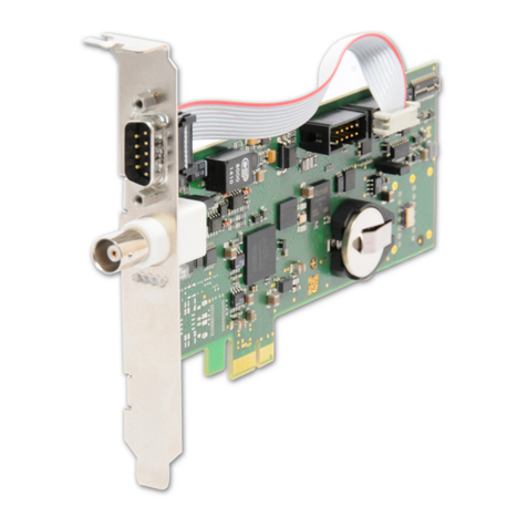
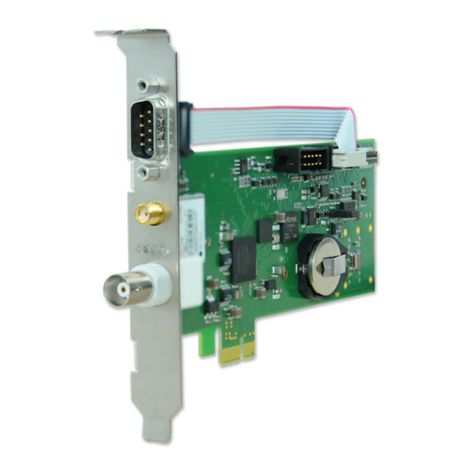
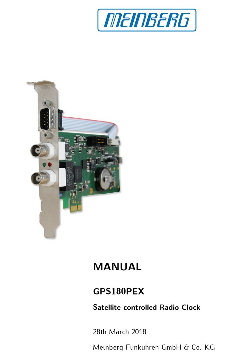
The satellite controlled clock GPS170PEX is designed as a standard height board for computers with PCI Express
interface. The data transfer to the computer is done by using a single PCI Express Lane (x1 board). The rear
slot cover integrates the antenna connector, the modulated timecode, two status LEDs, and a 9 pin SUB-D male
connector. Monitoring software shipped with the board can be used to check the clock's status and congure
some operational parameters.
The antenna/converter unit is connected to the receiver by a 50 O coaxial cable with length up to 300m (when
using RG58 cable). Power is supplied to the unit DC insulated across the antenna cable. Optionally, an over
voltage protection and an antenna distributor are available. The antenna distributor can be used to operate up
to 4 Meinberg GPS receivers using a single antenna/converter unit.
The navigation message coming in from the satellites is decoded by satellite clock's microprocessor in order
to track the GPS system time with an accuracy of better than 250nsec. Compensation of the RF signals prop-
agation delay is done by automatic determination of the receivers position on the globe. A correction value
computed from the satellites navigation messages increases the accuracy of the boards temperature compen-
sated master oscillator (TCXO) to +- 5(10
-9
) and automatically compensates the TCXOs aging. The last recent
value is restored from the nonvolatile memory at power-up. Optionally, the clock is also available with a higher
precision time base.
6.1 Time zone and daylight saving
GPS system time diers from the universal time scale (UTC) by the number of leap seconds which have been
inserted into the UTC time scale after GPS has been initiated in 1980. The current number of leap seconds is
part of the navigation message supplied by the satellites, so the satellite clocks internal real time is based on
UTC. Conversion to local time including handling of daylight saving year by year can be done by the receivers
microprocessor. For Germany, the local time zone is UTC + 3600 sec for standard time and UTC + 7200 sec if
daylight saving is in eect.
The clock's microprocessor determines the times for start and end of daylight saving time by a simple algo-
rithm e. g. for Germany:
Start of DST is on the rst Sunday after March, 25th, at 2 o'clock standard time.
End of DST is on the rst Sunday after October, 25th, at 3 o'clock daylight time.
The monitoring software shipped with the board can be used to congure the time zone and daylight savings
parameters easily. Switching to daylight saving time is inhibited if for both start and end of daylight saving the
parameters are exactly the same.
The timecode (IRIG, AFNOR, IEEE) generated by GPS170PEX is available with these settings or with UTC
as reference. This can be set by the monitor program.
6.2 Asynchronous serial ports
Two asynchronous serial interfaces (RS232) called COM0 and COM1 are available to the user. Only COM0 is
available at the rear panel slot cover, COM1 must use another submin-D connector which can optionally be con-
nected to the 5 pin jumper block on the board. The monitoring program can be used to congure the outputs. In
the default mode of operation, the serial outputs are disabled until the receiver has synchronized after power-up.
However, they can be congured to be enabled immediately after power-up.
Transmission speed, framing and mode of operation can be congured individually for each port. Both of the
6
Date: 2009-06-24 GPS170PEX
6.3 Time capture inputs Page 7
ports can be congured to transmit either time strings (once per second, once per minute, or on request with
ASCII ? only), or to transmit capture strings (automatically when available, or on request). The format of the
output strings is ASCII, see the technical specications at the end
of this document for details.
6.3 Time capture inputs
The board provides two time capture inputs called User Capture 0 and 1 (CAP0 and CAP1) which can be mapped
to pins at the 9 pin connector at the rear panel. These inputs can be used to measure asynchronous time events.
A falling TTL slope at one of these inputs lets the microprocessor save the current real time in its capture buer.
From the buer, an ASCII string per capture event can be transmitted via COM1 or displayed using the monitoring
program. The capture buer can hold more than 500 events, so either a burst of events with intervals down to
less than 1.5 msec can be recorded or a continuous stream of events at a lower rate depending on the transmission
speed of COM1 can be measured. The format of the output string is described in the technical specications at
the end of this document. If the capture buer is full a message "** capture buer full" is transmitted, if the
interval between two captures is too short the warning "** capture overrun" is being sent via COM1.
6.4 Pulse and frequency outputs
The pulse generator of the satellite controlled clock GPS170 contains three independent channels (PPO0, PPO1,
PPO2). These TTL outputs can be mapped to pins at the 9-pin connector at the rear slot cover by using a DIL
switch. The pulse generator is able to provide a multitude of dierent pulses, which are congured with the moni-
tor program. The active state of each channel is invertible, the pulse duration settable between 10 msec and 10 sec
in steps of 10 msec. In the default mode of operation the pulse outputs are disabled until the receiver has synchro-
nized after power-up. However, the system can be congured to enable those outputs immediately after power-up.
The following modes can be congured for each channel independently:
Timer mode:
Three on- and o-times per day per channel programmable
Cyclic mode:
Generation of periodically repeated pulses.
A cycle time of two seconds would generate a pulse at
0:00:00, 0:00:02, 0:00:04 etc.
DCF77-Simulation mode:
The corresponding output simulates the DCF77 time telegram.
The time marks are representing the local time as congured by the user.
Single Shot Mode:
A single pulse of programmable length is generated once a day at a
programmable point of time
Per Sec.
Per Min.
Per Hr. modes:
Pulses each second, minute or hour
Status:
One of three status messages can be emitted:
`position OK': The output is switched on if the receiver was able to
compute its position
`time sync': The output is switched on if the internal timing is
synchronous to the GPS-system
`all sync': Logical AND of the above status messages.
The output is active if position is calculated AND the
timing is synchronized
Idle-mode:
The output is inactive
The default conguration for the pulse outputs is:

PPO0:
Pulse each second (PPS), active HIGH, pulse duration 200 msec
PPO1:
Pulse each minute (PPM), active HIGH, pulse duration 200 msec
GPS170PEX Date: 2009-06-24
7
Page 8 6 GPS170PEX features
PPO2:
DCF77 Simulation
A TTL level master frequency of 10 MHz is derived from the TCXO. By default, this frequency is available only
at the 5 pin contact strip of the board.
6.5 DCF77 Emulation
The GPS170PEX satellite controlled clock generates TTL level time marks (active HIGH) which are compatible
with the time marks spread by the German long wave transmitter DCF77. This long wave transmitter installed
in Mainingen near Frankfurt/Germany transmits the reference time of the Federal Republic of Germany: time
of day, date of month and day of week in BCD coded second pulses. Once every minute the complete time
information is transmitted. However, GPS170PEX generates time marks representing its local time as congured
by the user, including announcement of changes in daylight saving and announcement of leap seconds. The coding
sheme is given below:
M Start of Minute (0.1 s)
R RF Transmission via secondary antenna
A1 Announcement of a change in daylight saving
Z1, Z2 Time zone identification
Z1, Z2 = 0, 1: Daylight saving disabled
Z1, Z2 = 1, 0: Daylight saving enabled
A2 Announcement of a leap second
S Start of time code information
P1, P2, P3 Even parity bits
0
10
20
30
40
50
R
M
1
4
2
1
20
10
8
4
2
1
P2
02
01
8
4
2
1
2
4
8
10
1
2
4
8
10
20
40
80
3
P
A1
Z1
Z2
A2
S
1
2
4
8
10
20
40
1P
Minute
(reserved)
Hour
Day of Month
Day of Week
Year of the Century
Month of Year
Time marks start at the beginning of new second. If a binary "0" is to be transmitted, the length of the
corresponding time mark is 100 msec, if a binary "1" is transmitted, the time mark has a length of 200 msec.
The information on the current date and time as well as some parity and status bits can be decoded from the
time marks of the 15th up to the 58th second every minute. The absence of any time mark at the 59th second
of a minute signals that a new minute will begin with the next time mark. The DCF emulation output is enabled
immediately after power-up.
8
Date: 2009-06-24 GPS170PEX
Page 9
7 Connectors and LEDs in the rear slot cover
GPS
antenna
10 MHz
standard frequency
LOCK FAIL
BSL key
RxD
TxD
GND
The coaxial antenna connector, two status LEDs and
a 9 pin sub D connector can be found in the rear slot
cover. (see gure). The upper, green LED (LOCK) is
turned on when after power-up the receiver has acquired
at least four satellites and has computed its position.
In normal operation the receiver position is updated
continuously as long
as at least four satellites can be received.
The lower, red LED (FAIL) is turned on after power-up
until the receiver has synchronized or if a severe error
occurs during operation.
The 9 pin sub D connector is wired to the GPS170PEX's
serial port COM0. Pin assignment can be seen from the
gure beside. This port can not be used as serial port
for the computer. Instead, it can be uses to send out
Meinberg's standard time string to an external device.
A DIL switch on the board can be used to wire some
TTL inputs or outputs (0..5V) to some connector pins.
In this case, absolute care must be taken if another
device is connected to the port, because voltage levels
of -12V through +12V (as commonly used with RS-232
po rts) at TTL inputs or outputs may damage the radio
clock.
Behind the little hole in the slot cover there is a push button (BSL) which is needed if the clock's rmware shall
be updated. See the chapter about rmware updates for details.
GPS170PEX Date: 2009-06-24
9
Page 10 7 Connectors and LEDs in the rear slot cover
7.1 Configuring the 9 pin connector
By default only the signals needed for the serial port COM0 are mapped to the pins of the connector. Whenever
one of the additional signals shall be used, the signal must be mapped to a pin by putting the appropriate lever
of the DIL switch in the ON position. The table below shows the pin assignments for the connector and the DIL
switch lever assigned to each of the signals. Care must be taken when mapping a signal to Pin 1, Pin 4 or Pin 7
of the connector, because one of two dierent signals can be mapped to these Pins. Only one switch may be put
in the ON position in this case:
Pin 1:
DIL 1 or DIL 8 ON
Pin 4:
DIL 5 or DIL 10 ON
Pin 7:
DIL 3 or DIL 7 ON
Those signals which do not have a lever of the DIL switch assigned are always available at the connector:
D-SUB-Pin Signal Signal level DIL-switch

1 VCC out +5V 1
1 PPO0 (PPS) out RS232 8
2 RxD in RS232 -
3 TxD out RS232 -
4 PPO1 (PPM) out TTL 5
4 10MHz out TTL 10
5 GND - -
6 CAP0 in TTL 2
7 CAP1 in TTL 3
7 IRIG DC out TTL into 50
Ω
7
8 PPO0 (PPS) out TTL 4
9 PPO2 (DCF) out TTL 9
7.2 Installing the GPS170PEX in your computer
Every PCI Express board is a plug&play board. After power-up, the computer's BIOS assigns resources like I/O
ports and interrupt numbers to the board, the user does not need to take care of the assignments. The programs
shipped with the board retrieve the settings from the BIOS.
The computer has to be turned o and its case must be opened. The radio clock can be installed in any
PCI Express slot not used yet. The rear plane must be removed before the board can be plugged in carefully. The
computers case should be closed again and the antenna can be connected to the coaxial plug at the clock's rear
slot cover. After the computer has been restarted, the monitor software can be run in order to check the clock's
conguration.The computers case should be closed again and the antenna must be connected to the appropriate
connector.
10
Date: 2009-06-24 GPS170PEX
7.3 Mounting the GPS Antenna Page 11
7.3 Mounting the GPS Antenna
The GPS satellites are not stationary, but circle round the globe with a period of about 12 hours. They can only
be received if no building is in the line-of-sight from the antenna to the satellite, so the antenna/downconverter
unit must be installed in a location that has as clear a view of the sky as possible. The best reception is achieved
when the antenna has a free view of 8
◦
angular elevation above the horizon. If this is not possible, the antenna
should be installed with the clearest free view to the equator, because the satellite orbits are located between
latitudes 55
◦
North and 55
◦
South. If this is not possible, you may experience diculty receiving the four satellites
necessary to complete the receiver's position solution.
The unit can be mounted using a pole with a diameter up to 60 mm. A standard coaxial cable with 50
Ω
impedance (e.g. RG58C) should be used to connect the antenna/converter unit to the receiver. Cable thinner
than RG58 should be avoided due to its higher DC resistance and RF attenuation. When using the optional
antenna diplexer the total length of one antenna line between antenna, diplexer and receiver must not be longer
than 300 m. If a cable with less attenuation is used its length may be increased accordingly (e.g. 700 m with
RG213).
Up to four GPS170 receivers can be run with one antenna/downconverter unit by using an optional antenna
splitter. The total length of one antenna line between antenna, splitter and receiver must not be longer than the
max. length shown in the table above. The position of the splitter in the antenna line does not matter.
High voltage protectors must be installed directly after reaching the indoors. The optional delivered protec-
tion kit is not for outdoor usage.
7.3.1 Example:
Type of cable diameter Ø [mm] Attenuation at max lenght. [m]
100MHz [dB]/100m
RG58/CU 5mm 17 300
(1)
RG213 10.5mm 7 700
(1)
(1)This specications are made for antenna/converter units produced after January, 2005
The values are typically ones; the exact ones are to nd out from the data sheet of the used cable
GPS170PEX Date: 2009-06-24
11
Page 12 7 Connectors and LEDs in the rear slot cover
7.3.2 Antenna Short-Circuit Assembly with surge voltage protection
Optional a surge voltage protector for coaxial lines is available. The shield has to be connected to earth as short
as possible by using the included mounting bracket. Standard you connect the antenna converter directly with
the antenna cable to the system.
free view to the equator!
Type N / BNC
male
Type N
female
Type N
female
Surge Voltage Protector
connect to earth by using the mounting bracket.
Type N
male
GPS
Antenna
Meinberg
GPS
s
S
a
t
P
elli
G
te ante
n
a
n
As short as possible!
cable slot
12
Date: 2009-06-24 GPS170PEX
7.4 Powering up the system Page 13
7.4 Powering up the system
After the board has been mounted and the antenna has been connected, the system is ready to operate. About
10 seconds after power-up the receivers TCXO operates with the required accuracy. If the receiver nds valid
almanac and ephemeris data in its battery buered memory and the receivers position has not changed signif-
icantly since its last operation the receiver can nd out which satellites are in view now. Only a single satellite
needs to be received to synchronize and generate output pulses, so synchronization can be achieved at least one
minute after power-up. After 20 minutes of operation the TCXO has achieved its nal accuracy and the generated
frequencies are within the specied tolerances.
If the receiver position has changed by some hundred kilometers since last operation, the satellites real ele-
vation and Doppler might not match those values expected by the receiver thus forcing the receiver to start
scanning for satellites. This mode is called Warm Boot because the receiver can obtain ID numbers of existing
satellites from the valid almanac. When the receiver has found four satellites in view it can update its new
position and switch to normal operation. If the almanac has been lost because the battery had been disconnected
the receiver has to scan for a satellite and read in the current almanacs. This mode is called Cold Boot. It
takes 12 minutes until the new almanac is complete and the system switches to Warm Boot mode scanning for
other satellites. In the default mode of operation, neither pulse outputs nor the serial ports will be enabled after
power-up until synchronization has been achieved.
However, it is possible to congure some or all of those outputs to be enabled immediately after power-up.
If the system starts up in a new environment (e. g. receiver position has changed or new power supply) it can
take some minutes until the TCXOs output frequency has been adjusted. Up to that time accuracy of frequency
drops to 10-8 reducing the accuracy of pulses to +-2
µ
s.
GPS170PEX Date: 2009-06-24
13
Page 14 8 Firmware updates
8 Firmware updates
Whenever the on-board software must be upgraded or modied, the new rmware can be downloaded to the
internal ash memory via the radio clock's serial port COM0. There is no need to open the computer case and
insert a new EPROM.
If the button behind a hole in the rear slot cover is pressed for approximately 2 seconds, a bootstrap loader
is activated and waits for instructions from the serial port COM0. A loader program shipped together with the
le containing the image of the new rmware sends the new rmware from one of the computer's serial ports to
the clock's serial port COM0. The bootstrap loader does not depend on the contents of the ash memory, so if
the update procedure is interrupted, it can easily be repeated.
The contents of the program memory will not be modied until the loader program has sent the command
to erase the ash memory. So if the button has been pressed accidentally, the system will be ready to operate
again after the computer has been turned o and then on again.
14
Date: 2009-06-24 GPS170PEX
Page 15
9 Skilled/Service-Personnel only: Replacing the
Lithium Battery
The life time of the lithium battery on the board is at least 10 years. If the need arises to replace the battery, the
following should be noted:
ATTENTION!
There is a Danger of explosion if the lithium battery is
replaced incorrectly. Only identical batteries or batter-
ies recommended by the manufacturer must be used for
replacement.
The waste battery has to be disposed as proposed
by the manufacturer of the battery.
GPS170PEX Date: 2009-06-24
15
Page 16 10 Time codes
10 Time codes
The transmission of coded timing signals began to take on widespread importance in the early 1950s. Especially
the US missile and space programs were the forces behind the development of these time codes, which were used
for the correlation of data. The denition of time code formats was completely arbitrary and left to the individual
ideas of each design engineer. Hundreds of dierent time codes were formed, some of which were standardized
by the Inter Range Instrumentation Group (IRIG) in the early 60s.
Except these IRIG Time Codes other formats, like NASA36, XR3 or 2137, are still in use. The board GPS170PEX
however generates the IRIG-B, AFNOR NFS 87- 500 code as well as IEEE1344 code which is an IRIG-B123 coded
extended by information for time zone, leap second and date. If desired other formats are available.
10.1 The time code generator
The board GPS170PEX generates modulated and un-modulated timecodes. Modulated signals are transmitting
the information by varying the amplitude of a sine wave carrier, un-modulated timecodes are transmitted by pulse
duration modulation of a DC-signal (TTL in case of GPS170PEX), see chapter IRIG standard format for details.
The sine wave carrier needed for modulated signals is generated in a digital way by a programmable logic device
on the board. The frequency of this signal is derived from the main oscillator of GPS170PEX, which is disciplined
by the GPS-system.
This leads to a sine wave carrier with high accuracy. Transmission of date is synchronized by the PPS (pulse per
second) derived from the GPS-system. The modulated time code has an amplitude of 3Vpp (MARK) and 1Vpp
(SPACE) into 50 O. The number of MARK-amplitudes within ten periods of the carrier denes the coding:
a) binary 0 : 2 MARK-amplitudes, 8 SPACE-amplitudes
b) binary 1 : 5 MARK-amplitudes, 5 SPACE-amplitudes
c) position-identier : 8 MARK-amplitudes, 2 SPACE-amplitudes
The DC-signal has the following pulse durations accordingly:
a) binary 0 : 2 msec
b) binary 1 : 5 msec
c) position-identier : 8 msec
16
Date: 2009-06-24 GPS170PEX
10.2 IRIG Standard Format Page 17
10.2 IRIG Standard Format
GPS170PEX Date: 2009-06-24
17

Other Meinberg Computer Hardware manuals

Meinberg CPU-C15G2 User manual

Meinberg

Meinberg CPU-C15G2 User manual

Meinberg IMS-VSG181H User manual

Meinberg

Meinberg IMS-VSG181H User manual

Meinberg BPE-2000 User manual

Meinberg

Meinberg BPE-2000 User manual

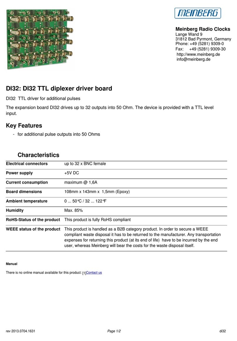
Meinberg DI32 User manual

Meinberg

Meinberg DI32 User manual

Meinberg TCR510PCI User manual

Meinberg

Meinberg TCR510PCI User manual

Meinberg Line InterfaceUnit v2.0 User manual

Meinberg

Meinberg Line InterfaceUnit v2.0 User manual

Meinberg LANTIME User manual

Meinberg

Meinberg LANTIME User manual

Meinberg TCR180 User manual

Meinberg

Meinberg TCR180 User manual

Meinberg IMS-LNO User manual

Meinberg

Meinberg IMS-LNO User manual

Meinberg GPS180PEX User manual

Meinberg

Meinberg GPS180PEX User manual

Meinberg GPS170PCI User manual

Meinberg

Meinberg GPS170PCI User manual

Meinberg GNS181PEX User manual

Meinberg

Meinberg GNS181PEX User manual

Meinberg IMS-GPS182 User manual

Meinberg

Meinberg IMS-GPS182 User manual

Meinberg TCR180PEX-EL User manual

Meinberg

Meinberg TCR180PEX-EL User manual

Meinberg GPS167PC User manual

Meinberg

Meinberg GPS167PC User manual

Meinberg DI/BGT TTL User manual

Meinberg

Meinberg DI/BGT TTL User manual

Popular Computer Hardware manuals by other brands

Asus AAEON GENESYS-CML5 user manual

Asus

Asus AAEON GENESYS-CML5 user manual

COBHAM NOEL-ARTYA7-EX quick start guide

COBHAM

COBHAM NOEL-ARTYA7-EX quick start guide

Artesyn ATCA-9305 quick start guide

Artesyn

Artesyn ATCA-9305 quick start guide

Link electronics Analog Pulse Generator 812-OP/H Specification sheet

Link electronics

Link electronics Analog Pulse Generator 812-OP/H Specification sheet

Digital Equipment MS11-BC Maintenance manual

Digital Equipment

Digital Equipment MS11-BC Maintenance manual

TERSUS Precis-BX305 quick start

TERSUS

TERSUS Precis-BX305 quick start

ZLG M.2CANFD user manual

ZLG

ZLG M.2CANFD user manual

Welch Allyn Connex CS install guide

Welch Allyn

Welch Allyn Connex CS install guide

Noctua NH-L12 Ghost S1 Edition installation manua

Noctua

Noctua NH-L12 Ghost S1 Edition installation manua

IEI Technology IDS-330-ADL-P Series user manual

IEI Technology

IEI Technology IDS-330-ADL-P Series user manual

Belkin F5U252ea user manual

Belkin

Belkin F5U252ea user manual

Exsys EX-41150 user manual

Exsys

Exsys EX-41150 user manual

Solidyne 542 APC owner's manual

Solidyne

Solidyne 542 APC owner's manual

Rimage Producer III 6100N user guide

Rimage

Rimage Producer III 6100N user guide

Pepperl+Fuchs BTC22 Series manual

Pepperl+Fuchs

Pepperl+Fuchs BTC22 Series manual

Abbingdon Music Research CD-77 owner's manual

Abbingdon Music Research

Abbingdon Music Research CD-77 owner's manual

Omron G2RS manual

Omron

Omron G2RS manual

Breville BFP300 instructions

Breville

Breville BFP300 instructions

manuals.online logo
manuals.online logoBrands
  • About & Mission
  • Contact us
  • Privacy Policy
  • Terms and Conditions

Copyright 2025 Manuals.Online. All Rights Reserved.