EASTMAN Kodak X-Omat 180 LP User manual

© Eastman Kodak Company
Publication No. 1C7836
February 1996
Supersedes July 1995
INSTALLATION INSTRUCTIONS for the
Kodak X-Omat
180 LP and 180 LPS
PROCESSORS
H127_0010DA

2 February 1996 – 1C7836
PLEASE NOTE The information contained herein is based on the experience and knowledge relating to the
subject matter gained by Eastman Kodak Company prior to publication.
No patent license is granted by this information.
Eastman Kodak Company reserves the right to change this information without notice, and
makes no warranty, express or implied, with respect to this information. Kodak shall not be liable
for any loss or damage, including consequential or special damages, resulting from any use of
this information, even if loss or damage is caused by Kodak’s negligence or other fault.
This equipment includes parts and assemblies sensitive to damage from electrostatic
discharge. Use caution to prevent damage during all service procedures.
Description Page
Table of Contents
Electrostatic Discharge . . . . . . . . . . . . . . . . . . . . . . . . . . . . . . . . . . . . . . . . . . . . . . . . . . . 3
Preparing the PROCESSOR for Installation . . . . . . . . . . . . . . . . . . . . . . . . . . . . . . . . . . . 4
Special Tools Required . . . . . . . . . . . . . . . . . . . . . . . . . . . . . . . . . . . . . . . . . . . 4
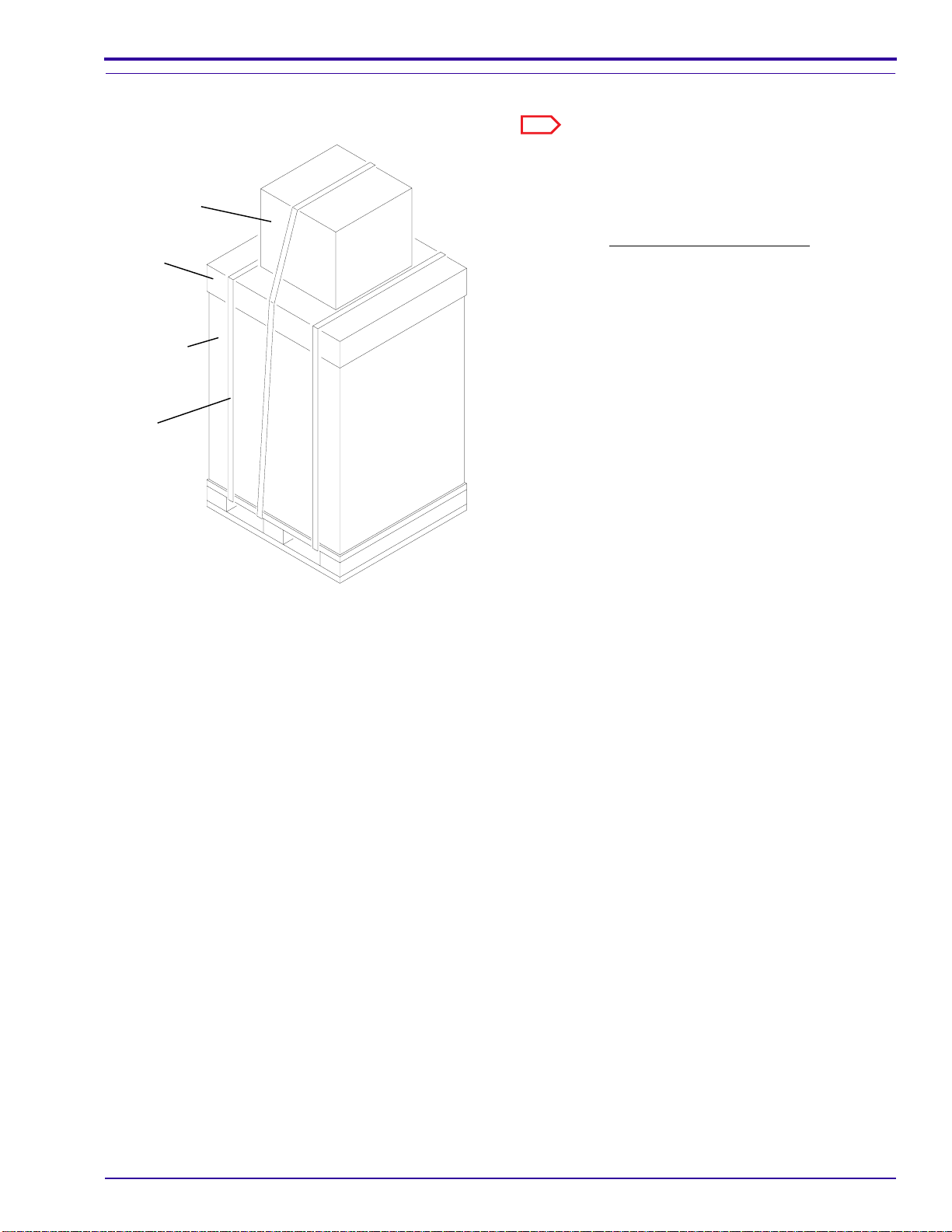
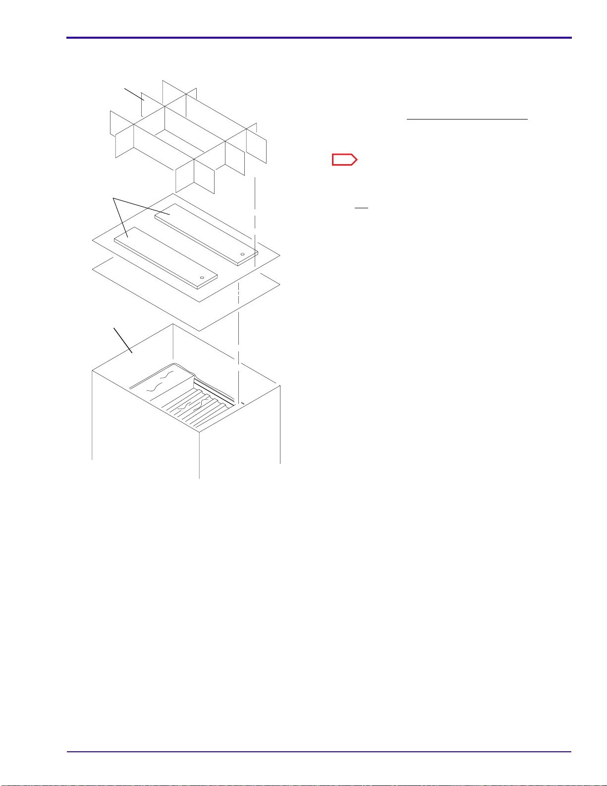
Unpacking the PROCESSOR . . . . . . . . . . . . . . . . . . . . . . . . . . . . . . . . . . . . . . 5
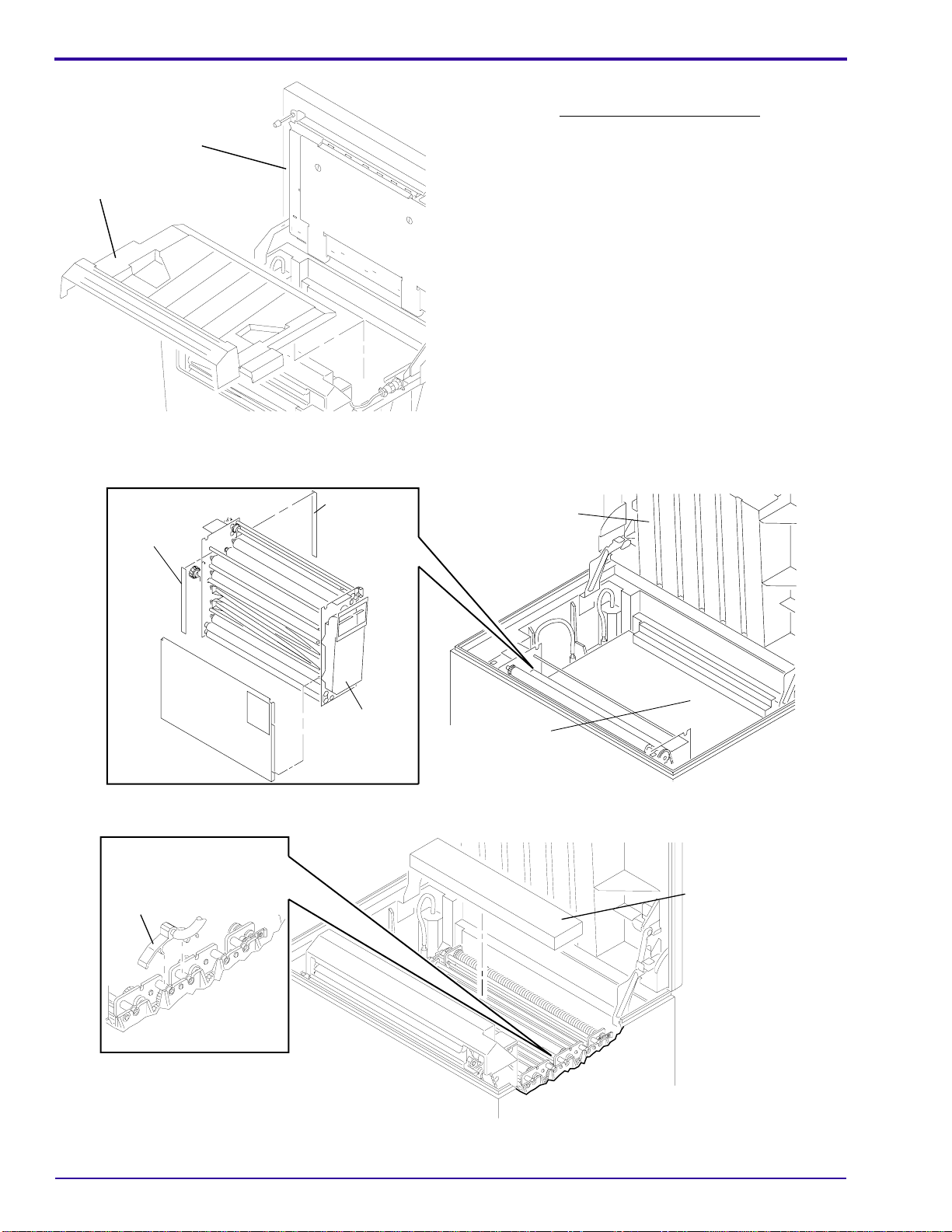
Checking the DRIVE SHAFT SPROCKET . . . . . . . . . . . . . . . . . . . . . . . . . . . . 12
Installing the RACKS . . . . . . . . . . . . . . . . . . . . . . . . . . . . . . . . . . . . . . . . . . . . . 13
Moving the PROCESSOR into Position and Leveling the PROCESSOR . . . . . 15
Measuring the Distance between the SORTER and the Processing TANK . . . 17
Connecting the PROCESSOR . . . . . . . . . . . . . . . . . . . . . . . . . . . . . . . . . . . . . . . . . . . . . 18
Installing the SEISMIC KIT. . . . . . . . . . . . . . . . . . . . . . . . . . . . . . . . . . . . . . . . . 18
Tightening the CLAMPS . . . . . . . . . . . . . . . . . . . . . . . . . . . . . . . . . . . . . . . . . . 18
Making the Electrical Connections . . . . . . . . . . . . . . . . . . . . . . . . . . . . . . . . . . 19
Connecting the Water Supply . . . . . . . . . . . . . . . . . . . . . . . . . . . . . . . . . . . . . . 27
Connecting the Drains . . . . . . . . . . . . . . . . . . . . . . . . . . . . . . . . . . . . . . . . . . . . 28
Connecting the REPLENISHER TANKS and STRAINERS . . . . . . . . . . . . . . . 30
Connecting the EXHAUST DUCT from the DRYER . . . . . . . . . . . . . . . . . . . . . 31
Installing the DEVELOPER FILTER . . . . . . . . . . . . . . . . . . . . . . . . . . . . . . . . . 32
Checking for Correct Operation . . . . . . . . . . . . . . . . . . . . . . . . . . . . . . . . . . . . . . . . . . . . 33
Checking the Components and SENSORS . . . . . . . . . . . . . . . . . . . . . . . . . . . . 33
Checking the SORTER, 180 LPS PROCESSOR Only . . . . . . . . . . . . . . . . . . . 35
Checking the Adjustment of the ACCESS DOOR LATCH on the SORTER . . . 38
Continuing to Check the Components . . . . . . . . . . . . . . . . . . . . . . . . . . . . . . . . 39
Calibrating the Replenishment System . . . . . . . . . . . . . . . . . . . . . . . . . . . . . . . 40
Publication History . . . . . . . . . . . . . . . . . . . . . . . . . . . . . . . . . . . . . . . . . . . . . . . . . . . . . . 41

Electrostatic Discharge
1C7836 – February 1996 3
Section 1: Electrostatic Discharge
Overview ESD — electrostatic discharge — is a primary source of:
• product downtime
• lost productivity
• costly repairs
While one cannot feel a static charge of less than 3,500 volts, as few as 30 volts can damage or destroy
essential components in electronic equipment.
Preventive Measures
• Always look for an ESD warning label before doing any procedure involving static-sensitive
components such as CIRCUIT BOARDS. All static-sensitive components are marked with bright
graphic labels, which frequently include instructions. Follow all label instructions.
• Wear a grounding strap when handling static-sensitive components. Always make certain that the
clip remains attached to a properly grounded, unpainted, clean surface.
• Repair static-sensitive components at an ESD-protected work station or use a portable grounding
mat. For help in setting up an ESD-protected work station, contact your Kodak representative.
• When moving static-sensitive components from one area to another, insert and transport the
components in ESD-protective packaging. Transparent antistatic bags are available from a variety
of manufacturers and will help shield components from ESD damage.

INSTALLATION INSTRUCTIONS
4 February 1996 – 1C7836
Section 2: Preparing the PROCESSOR for Installation
Special Tools Required
The following tools are required:
Note
* The following relates to the PORTABLE COMPUTER:
• An IBM compatible PORTABLE COMPUTER with MS-DOS version 3.0 or higher installed on the hard disk and
with a 720 KB 31/2in. disk drive.
• A serial communication port configured as COM1: See the User Manual for the PORTABLE COMPUTER.
Important
• Use only qualified personnel to install the PROCESSOR.
• Before installation of the PROCESSOR, review the Section “Electrostatic Discharge” on Page 3to ensure that
components do not become damaged during installation of the JUMPERS in the PROCESSOR.
Tool or
Part No. Description
--- PORTABLE COMPUTER *
TL-1434 LEVEL - approximately 30.5 cm (12 in.)
TL-1926 MAGNETIC POWER WARNING SIGN
TL-2431 AIR METER
TL-2296 TAPE MEASURE
TL-4391 INTERFACE CABLE
5B6278 DIAGNOSTICS DISKETTE

Preparing the PROCESSOR for Installation
1C7836 – February 1996 5
Unpacking the PROCESSOR
Note
Install the PROCESSOR before you install the
Kodak
Ektascan
2180 LASER PRINTER.
[1] Cut and remove the bands around the outside of
the SHIPPING CARTON.
[2] For the 180 LPS PROCESSOR only, remove the
SORTER BIN from the top of the main SHIPPING
CARTON.
[3] Remove the CARDBOARD COVER from the
SHIPPING CARTON.
H127_0208GA
H127_0208GCA
band
CARTON
SHIPPING
COVER
CARDBOARD
SORTER BIN

INSTALLATION INSTRUCTIONS
6 February 1996 – 1C7836
[4] Remove:
• GRADUATED CYLINDERS
• EXIT RACK
• DETECTOR CROSSOVER
• DRIP TRAY and SPLASH GUARD
• PROCESSOR DOCKING ASSEMBLY
• PREPACK POLYBAG
Note
The PROCESSOR DOCKING ASSEMBLY is not used during the installation of the PROCESSOR.
H127_0195DA
H127_0195DCA
CROSSOVER
DETECTOR
CYLINDERS
GRADUATED
ASSEMBLY
DOCKING
PROCESSOR
EXIT RACK
PREPACK POLYBAG
SPLASH GUARD
and
DRIP TRAY

Preparing the PROCESSOR for Installation
1C7836 – February 1996 7
[5] Remove the:
• PACKING MATERIAL from the top of the
PROCESSOR
• RAMPS with the BOLTS
• For the 180 LP PROCESSOR only, the
service publication, Publication Part
No. 1C7834
Note
The service publication for the 180 LPS PROCESSOR
will be removed later in the unpacking procedure.
[6] Lift the SHIPPING CARTON to remove it from the
PROCESSOR.
[7] Remove the plastic from the PROCESSOR.
[8] Check that the contents of the SHIPPING
CARTON match the Packing List.
H127_0056CA
H127_0056CCA
CARTON
SHIPPING
PACKING
MATERIAL
RAMPS

INSTALLATION INSTRUCTIONS
8 February 1996 – 1C7836
[9] Lift the TOP COVER of the PROCESSOR.
[10] For the 180 LPS PROCESSOR only, remove the
FILM TRAY.
[11] Remove the WET SECTION COVER and the PACKING MATERIAL around it.
[12] Remove the DRYER RACK and the 2 pieces of PACKING MATERIAL inside the DRYER.
[13] Remove the YOKE and the EVAPORATION COVERS.
H127_0196AA
H127_0196ACA
FILM TRAY
TOP COVER
H127_0062BA
H127_0062BCA
COVER
WET SECTION
TOP COVER
RACK
DRYER
MATERIAL
PACKING PACKING
MATERIAL
H127_0197BA
H127_0197BCA
YOKE COVERS
2 EVAPORATION

Preparing the PROCESSOR for Installation
1C7836 – February 1996 9
[14] Remove the DEVELOPER/FIXER CROSSOVER and the FIXER/WASH CROSSOVER.
[15] Disconnect the WATER DISCONNECT.
[16] Remove:
• WASH RACK
• FIXER RACK
• DEVELOPER RACK
• packing materials
H127_0060DA
H127_0060DCA
P/J33
WASH RACK CROSSOVER
FIXER/WASH FIXER RACK
CROSSOVER
DEVELOPER/FIXER
DEVELOPER RACK
DRYER RACK
EXIT RACK
DISCONNECT
WATER

INSTALLATION INSTRUCTIONS
10 February 1996 – 1C7836
Note
To remove a PANEL:
• Loosen the CAPTIVE SCREWS.
• Lift the PANEL and remove.
[17] Remove:
• tape
• FEED SIDE PANEL
• DRYER SIDE PANEL
[18] For the 180 LPS PROCESSOR only, remove the service publication, Publication Part No. 1C7834.
[19] Close the TOP COVER.
H127_0194HA
H127_0194HCA
DRYER SIDE PANEL
1C7834
PANEL
DRIVE SIDE SIDE PANEL
NON-DRIVE
FEED SIDE PANEL
TOP COVER
BREAKER CB1
MAIN CIRCUIT

Preparing the PROCESSOR for Installation
1C7836 – February 1996 11
Moving the PROCESSOR off the PALLET
[20] Install the RAMPS onto the PALLET.
[21] Insert the BOLTS into the holes in the RAMP through the PALLET.
Important
Do not use the TOP COVER to move the PROCESSOR.
Warning
The PROCESSOR weighs over 135 kg (300 lb) and is on casters. Personnel injury could occur if adequate
assistance is not taken.
[22] Carefully move the PROCESSOR off the PALLET onto the RAMPS and onto the floor.
[23] LifttheTOPCOVERandremovetheDRIVESIDE
PANEL and the NON-DRIVE SIDE PANEL.
[24] Remove the TAPE holding the ELECTRICAL
BOX.
H127_0143BA
H127_0143BCA
BOLT
PALLET
RAMPS
H127_0084AA
H127_0084ACA
ELECTRICAL
BOX
TAPE

INSTALLATION INSTRUCTIONS
12 February 1996 – 1C7836
Checking the DRIVE SHAFT SPROCKET
Note
The 180 LPS PROCESSOR uses an ENCODER WHEEL/SPROCKET, and not a DRIVE SHAFT SPROCKET.
[1] Remove the 2 SCREWS and the DRIVE CHAIN COVER.
Important
For 60 Hz operation, use the 20-tooth DRIVE SHAFT SPROCKET. For 50 Hz operation, use the 17-tooth DRIVE
SHAFT SPROCKET.
[2] Check that the correct DRIVE SHAFT SPROCKET is installed in the PROCESSOR.
[3] To change the DRIVE SHAFT SPROCKET, do the following steps.
(a) Loosen the 4 SCREWS from the MOTOR BRACKET.
(b) Lift the DRIVE MOTOR and remove the DRIVE CHAIN.
(c) Remove the E-RING and WASHER from the feed end of the DRIVE SHAFT.
(d) For access to the SPROCKET PIN, move the DRIVE SHAFT toward the DRYER end of the
PROCESSOR.
(e) Remove the SPROCKET PIN and the DRIVE SHAFT SPROCKET.
(f) Install the new DRIVE SHAFT SPROCKET.
(g) Reverse the above procedure to assemble.
H127_0199BA
H127_0199BCA
4 SCREWS
DRIVE MOTOR
MOTOR BRACKET
feed end
DRIVE SHAFT SPROCKET
SHAFT
DRIVE
WASHER
E-RING
SPROCKET PIN
SPROCKET
WHEEL/
ENCODER
180 LPS
CHAIN
DRIVE
DRIVE CHAIN COVER
2 SCREWS

Preparing the PROCESSOR for Installation
1C7836 – February 1996 13
Installing the RACKS
Note
The RACKS and CROSSOVERS have WASHERS,
that identify them; “D” indicates DEVELOPER and “F”
indicates FIXER.
[1] Check the squareness of each RACK and
CROSSOVER before installing it. See the RACK
section of Adjustments and Replacments,
Publication Part No. 1C7837, for the procedures
to check for squareness.
[2] Install the:
• DEVELOPER RACK
• FIXER RACK
• WASH RACK
• DRYER RACK
• DETECTOR CROSSOVER
• DEVELOPER/FIXER CROSSOVER
• FIXER/WASH CROSSOVER
• EXIT RACK
H127_0148AA
H127_0148ACA
D/F or F/W
WASHER
H127_0147BA
EXIT RACK
DRYER RACK
DETECTOR CROSSOVER
DEVELOPER RACK
DEVELOPER/FIXER
CROSSOVER
FIXER RACK
FIXER/WASH
CROSSOVER
WASH RACK
H127_0147BCA

INSTALLATION INSTRUCTIONS
14 February 1996 – 1C7836
The Correct Position of the EXIT RACK LOCKING TABS
Important
The EXIT RACK LOCKING TABS must be in the correct positions.
[3] Check that all the RACKS are seated correctly.
[4] Connect the WATER DISCONNECT on the WASH RACK. Check that the WATER DISCONNECT is correctly
seated. See the figures on Pages 8and 9.
[5] Connect the YOKE between the DEVELOPER/FIXER and FIXER/WASH CROSSOVERS.
[6] Connect CONNECTOR P/J33.
H127_0145BA
H127_0145BCA
EXIT
RACK
LOCKING
TABS
CONNECTOR
P/J-33

Preparing the PROCESSOR for Installation
1C7836 – February 1996 15
Moving the PROCESSOR into Position and Leveling the PROCESSOR
[1] Install the LEVELING SCREW into the PROCESSOR BASE.
[2] Install the LEVELING FOOT by rotating it counterclockwise onto the LEVELING SCREW.
Note
The LEVELING FOOT must be past the threads so that it pivots on the end of the LEVELING SCREW. Check that
the LEVELING FOOT remains in this position until it touches the floor.
[3] Install the JAM NUT.
Note
Do not tighten the JAM NUT.
[4] Install the other 3 LEVELING SCREWS.
H127_0083BA
H127_0083BCA
FOOT
LEVELING BASE
PROCESSOR
LEVELING SCREW
JAM NUT

INSTALLATION INSTRUCTIONS
16 February 1996 – 1C7836
[5] Move the PROCESSOR into its operating position.
Important
Processor leveling is important for all PROCESSORS, but is critical for the SORTER to operate correctly on the
180 LPS PROCESSOR.
[6] Adjust the 4 LEVELING SCREWS until:
• The top of the REAR SITE TAB is 69.85 cm .16 cm (27
1/2in. 1/6 in.) above the floor. Use the TAPE
MEASURE TL-2296.
• The PROCESSOR is leveled from side-to-side and front-to-back. Use LEVEL TL-1434.
[7] Tighten the JAM NUTS on the LEVELING SCREWS.
69.85 cm
(27.50 in.)
H127_0081BA
H127_0081BCA
REAR
SITE
TAB
H127_0185AA
H127_0185ACA
TL-1434
H127_0186AA
TL-1434
H127_0186ACA

Preparing the PROCESSOR for Installation
1C7836 – February 1996 17
Measuring the Distance between the SORTER and the Processing TANK
Important
Correct leveling of the PROCESSOR is critical for adjusting the height of the SORTER.
[1] Move the SORTER to the down position.
[2] Adjust the height of the SORTER.
(a) Loosen the JAM NUTS on the SPINDLES.
Note
If necessary, lift the back SPINDLE to allow adjustment of the front SPINDLE.
(b) Adjust the front SPINDLE until the height of the SORTER is 8 cm (3.175 or 3 11/64 in.) 1.3mm ( 0.050 or
3/64 in.). See the figure.
(c) Observe the figure carefully to check that you are measuring from the correct points.
(d) Adjust the back SPINDLE until it just touches the TANK.
(e) Tighten the JAM NUTS.
8 cm
(3.175 in.)
H127_2033BA
SPINDLE
TANK
JAM NUT
front
TANK H127_2033BCA
back

INSTALLATION INSTRUCTIONS
18 February 1996 – 1C7836
Section 3: Connecting the PROCESSOR
Installing the SEISMIC KIT
[1] If necessary, install the SEISMIC BRACKETS provided in the SEISMIC KIT, Part No. 981278.
Note
The SEISMIC KIT only includes 4 BRACKETS, 8 WASHERS, 8 JAM NUTS, and instructions. The customer is
responsible for obtaining the ANCHORS, WASHERS, and BOLTS.
Tightening the CLAMPS
Note
Alladjustable metalband CLAMPSused to hold theTUBING to the FITTINGSin the PROCESSOR must be checked
for tightness when the PROCESSOR is installed. Although a CLAMP may be properly tightened at the factory,
shrinkage of the plastic TUBING will occur within a few weeks. Check and tighten the CLAMPS within 2 to 4 weeks
after installation of the PROCESSOR and when replacement TUBING is installed with adjustable band CLAMPS.
[1] Tighten the CLAMPS.
H127_0063BA
to FRAME
NUT welded
FOOT
LEVELING
SCREW
LEVELING
JAM NUT
WASHER
BRACKET
BOLT
ANCHOR
ANCHOR
H127_0063BCA
ANCHOR
WASHER

Connecting the PROCESSOR
1C7836 – February 1996 19
Making the Electrical Connections
Warning
Dangerous Voltage.
Important
All electrical services, including earth ground, must comply with local and national electrical codes.
Table 3–1 Service Options
Note
*L1/L2/N or L1/L2/L3/N may be used.
**L1/L2 or L1/L2/L3 may be used.
Warning
Dangerous Voltage. Move the main wall CIRCUIT BREAKER to “OFF”. Lock the main wall CIRCUIT BREAKER
and attach a MAGNETIC POWER WARNING SIGN TL-1926 to warn others not to energize the PROCESSOR while
you perform service. Move the CB1 on the PROCESSOR to the “O” position.
[1] Install the correct hardware in the AC POWER INPUT opening.
[2] Insert the customer’s main input power wires through the AC POWER INPUT opening.
Voltage
in volts Frequency
in Hz Service
200 50/60 2-wire, single phase
220 50/60 2-wire, single phase
230 50/60 2-wire, single phase
240 50/60 2-wire, single phase
100/200 50/60 3-wire, single phase
120/240 60 3-wire, single phase
120/208 60 3 or 4-wire, 3-phase*
127/220 50 3 or 4-wire, 3-phase*, wye
220/380 50 3 or 4-wire, 3-phase*, wye
230/400 50 3 or 4-wire, 3-phase*, wye
240/415 50 3 or 4-wire, 3-phase*, wye
200/200 50/60 2 or 3-wire, 3-phase**,
delta

INSTALLATION INSTRUCTIONS
20 February 1996 – 1C7836
[3] Remove the EMI FILTER COVER.
[4] Find the customer’s electrical service on the Power Connection Charts on Pages 21 - 26 .
• Connect the main input power wires to TB1 as shown on the Power Connection Charts. Check that the
connections are tight.
• Connect wires 1 - 4 from the PROCESSOR to TB1 as shown on the Power Connection Charts.
• Use the JUMPERS from the PREPACK POLYBAG to make the connections on TB2 and TB3 as shown on
the Power Connection Charts.
[5] Connect the incoming ground to the GROUND LUG on the PROCESSOR.
[6] Apply the correct UL/CSA or VDE Label on the drive side, on the inside of the TANK.
UL/CSA or VDE Label
H127_0053BA
H127_0053BCA
TB1
GROUND LUG
COVER
FILTER
EMI
TB3
TB2
AC POWER INPUT
KODAK
X-OMAT 180 LP Processor
SERVICE
CODE SERIAL
NUMBER
3227
LISTED 115B
Made in USA by
Eastman Kodak Company
Rochester, New York 14650
200V-23 AMP 50/60Hz 3PH 3W 220V-23 AMP 50/60Hz 1PH 2W
230V-23 AMP 50/60Hz 1PH 2W 240V-23 AMP 50/60Hz 1PH 2W
100/200V-23 AMP 50/60Hz 1PH 3W 120/240V-23 AMP 60Hz 1PH 3W
120/208V-24 AMP 60Hz 3PH 4W 127/220V-23 AMP 50Hz 3PH 4W
220/380V-12 AMP 50Hz 3PH 4W 230/400V0-13 AMP 50Hz 3PH 4W
240/415V-13 AMP 50Hz 3PH 4W
H127_0198BA
H127_0198BCA
here
label
apply
side
drive
Other manuals for Kodak X-Omat 180 LP
2
This manual suits for next models
1
Table of contents
Other EASTMAN Computer Hardware manuals
Popular Computer Hardware manuals by other brands

Global Fire Equipment
Global Fire Equipment J-NET-SP installation manual

Hama
Hama SATA PCI 2-Way Raid Controller Instruction guide

Noctua
Noctua NH-L12 Ghost S1 Edition installation manua

Alphacool
Alphacool NexXxoS GPX-N 780-M01 instructions

Profichip
Profichip VPC3+S user manual

Thermalright
Thermalright Silver Arrow SB-E manual