EASTMAN ESM3K/48 User manual

CORPORATE OFFICE
EASTMAN AUTO & POWER LTD.
547, Udyog Vihar, Phase-V, Gurgaon-122016, Haryana, India.
India Toll Free No. 1800 419 8610
+91 124 4682600/2610 | [email protected]

ESM3K/48, ESM5K/96, ESM7K5/120, ESM10K/120
SOLAR OFF-GRID MPPT PCU
ŸAdvanced MPPT technology ensures upto 30% more
energy extraction from Solar panel as compared to PWM
based technology
ŸIntelligent selection modes for high/medium/low power
cut areas
ŸPure sine-wave output
ŸAdvanced DSP based technology
ŸLCD Screen for user convenience
ŸUser configurable parameters through front end wide
screen LCD display
ŸIntelligent mixing of Grid current with solar in case of solar
energy shortfall during cloudy days
ŸHighest efficiency in its class
ŸBuilt-in energy meter for Mains, Battery, Solar and Load
ŸTemperature compensated (ATC) charging to enhance
the performance and life of battery upto 30%
ŸRemote monitoring and data logging feature
User Manual
www.eastmangroup.co.in | www.eaplworld.com
Before connecting, operating or adjusting this unit, please read this instruction booklet carefully.

OUR ACHIEVEMENTS
Established in
1970
2000 Crore
Turnover
2500+ Happy
Employees Presence in 105
Countries
About Us
The Eastman Global group began its journey in the year 1970
with presence in over 105 countries and a 2200+ loyal
distributor and dealer network across the world. Eastman Auto &
Power Limited instituted by Eastman group is a leading
manufacturer of Tall Tubular Batteries, Tubular Gel SMF
Batteries, Solar Batteries, E-Rickshaw Batteries & Automotive
Batteries, and offers a wide range of inverters, solar panels and
top of the line solar products that are widely known for their
innovative technology.

01
Important Safety Instructions
02
MPPT PCU Installation
A. General Instructions
B. Safety Warnings
A. Visual Check of PCU
B. PCU Installation Guide
C. Installation Safety Instruction
D. Storage Instructions
03
04
Know Your Off-Grid MPPT PCU
Operating Instructions
A. PCU System Description
B. Front Panel Description
C. Back Panel Description
D. Wiring Diagram
E. How To Configure
F. Three Intelligent Working Modes
06
05
Maintenance Instructions
Troubleshooting Guide
07
Off-Grid MPPT PCU
Technical Specifications
08
Warranty Card
The Content

A. General Instruction
1. All instructions should be read and understood before attempting to install, operate,
and maintain your Off-Grid MPPT PCU.
2.The handling, installation & maintenance of the battery associated with this
equipment, must be done in accordance with the instructions & safety precautions
given by the battery manufacturer.
3. Risk of a possible electrocution is possible when the battery is connected to the PCU.
Therefore, do not forget to disconnect the batteries, grid, PV Module, load before any
service is to be done on the PCU.
4. Installation, maintenance & repair of the equipment should be undertaken by trained,
experienced and authorized service or electrical personnel.
5. To disconnect, turn off all MCBs located at the back panel of PCU.
We request you to read the Manual prior to installation, performing start
up procedures, system operation & maintenance. Should you require any
assistance for more information on installation, please contact our India
Toll Free No. 1800 419 8610
B. Safety Warnings
1. Environmental Safety
PCU packing must be recycled in compliance with regulations.
Battery contains Lead and is dangerous substance for the environment hence
same shall be dispose of by Govt. approved agency only.
Important Safety
Instructions
SOLAR OFF-GRID MPPT PCU, PAGE 01, Ver. 1.0

2. User Safety
Grounding of the PCU & PV Module is necessary before connecting power supply.
Therefore, connect to ground prior to commissioning. Improper connection may
damage the device and lead to injuries.
3. Product Safety
Ÿ Suitable upstream protection must be installed with easy access to operators.
PCU should be installed at dry area, free from any water seepage and water
logging.
Ÿ Place the PCU in a room with proper ventilation and safe distance. All ventilation
apertures must be kept free and clean. Refer to manual to perform installation.
Ÿ Avoid installing the PCU in location under direct sunlight, running water, or
excessive humidity.
Ÿ Routine preventive check should be carried out.
Ÿ Store the Solar PCU in its original packing keeping the arrow on the box
pointing vertically upward.
Ÿ Store it in dry location. Storage temperature must be between 0°C to 70°C.
Ÿ Suitable handling equipment should be used for handling of PCU.
Ÿ The route / passage up to the installation site and the actual foundation
location must be capable of supporting the weight of the Solar PCU and its
accessories.
Hazardous voltage levels are present within the PCU. PCU should
be opened by qualified engineer only.
The interior of the Solar PCU cubical, after it is installed, has
hazardous AC & DC voltages on exposed terminals and printed circuit
boards. This condition prevails even when all the switches are OFF.
SOLAR OFF-GRID MPPT PCU, PAGE 02, Ver. 1.0

MPPT PCU
Installation
Please immediately contact Service person, Dealer or Transport agency if the
following conditions occur - 1. Any damage observed, either external or
internal. 2. Any accessory is missing or damaged.
SOLAR OFF-GRID MPPT PCU, PAGE 03, Ver. 1.0
A. Visual Check of PCU
When you receive your Off-Grid MPPT PCU, please carry out visual check for any damage
during transport.
B. PCU Installation Guide
Ÿ The system must be installed in a dry & clean room. To have proper ventilation, the user
must ensure enough air exchange in the room.
Ÿ Never install the equipment near liquids or in an excessively damp environment.
Ÿ Never block the ventilation grates.
We suggest the following for best results of installation -
- Minimum distance from the rear wall = 500 mm
- Minimum distance from the top = 500 mm
- Minimum distance from the front wall = 500 mm

C . Installation Safety Instructions
Ÿ Keep the Battery, PV Module, Grid Input & Output MCBs in "OFF" position during
installation.
Ÿ Connect Grid Input, PV Module & Battery supply to PCU.
Ÿ Ensure correctness of the polarity of battery & Solar PV Module connections.
Ÿ Ensure proper earthing of the equipment.
Ÿ Connect load cables.
Ÿ For PV Module readily accessible disconnection device (MCB/MCCB) shall be
incorporated in the distribution.
Ÿ After complete installation to power up system switch ON the Batt. MCB, for battery
voltage >96V . Press Soft start switch for 30 sec to charge the capacitor before
switching ON the battery MCB. Solar Charging will start.
Ÿ Press the Reset Switch to PCU ON. Thereafter switch ON the Output MCB. Now load will
run on PCU Output.
Ÿ After Connecting Mains Supply switch ON the GRID MCB.
D. Storage Instructions
Ÿ Carefully store your PCU in vertical position if system is not installed. Ensure to store
your PCU in a dry and sheltered environment.
Ÿ Cover it with an envelope so that it is protected from dust.
Ÿ If period of PCU installation is over 6 months, be sure to charge batteries for atleast 8
hours before the first use.
SOLAR OFF-GRID MPPT PCU, PAGE 04, Ver. 1.0

SOLAR OFF-GRID MPPT PCU, PAGE 05, Ver. 1.0
Know Your Off-Grid
MPPT PCU
A. PCU System Description
Your Off-Grid MPPT PCU is a pure sinewave single phase output system.
In normal mode, PCU operates from battery or solar power source and produces
single phase AC output to cater the load requirement.
MPPT based Solar charge controller, supplies DC power for battery charging as well as
for the PCU.
If solar is unavailable or is available in lesser amount, connected batteries will go into
discharge mode and grid input will get triggered automatically at certain
predetermined battery voltage level. Grid Input source takes care of output load and
starts battery charging till sufficient battery charge level is reached.
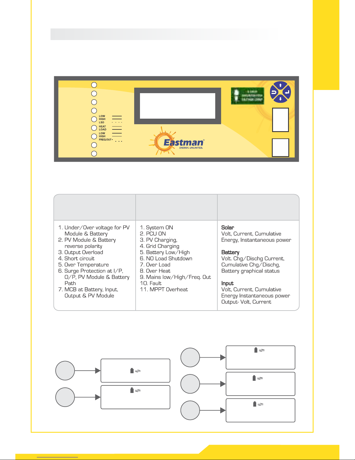
1. Internal Components
System comprises the following main control boards.
a) Control Board
b) Display Board
a. Control Board: It controls operation of MPPT charger and PCU. It contains power
modules of MPPT and PCU. MPPT receives DC supply from solar array and provides
charging voltage to battery and DC voltage for PCU operation. This board also
contains Power relays for grid and PCU, based on signal from DSP board transfer
operation is controlled and Output is available at load.
b. Display Board: It receives all inputs from Control Board. It displays parameters of PV
Module, Battery, PCU and Grid.
2. Operating Priority
a. Smart Mode/SBG Priority - Your PCU gives fisrt priority to solar, second priority to
battery and third priority to grid in this case.
b. PCU Mode/SGB Priority - Your PCU gives fisrt priority to solar, second priority to grid
and third priority to battery in this case.
c. Hybrid Mode - In this mode PCU works with solar as well as batteries. Grid charger
takes place only when solar power is not available & battery discharges up to battery
low level trip. It will charge the batteries up to certain limit to maintain float level of
battery.

BATT.
OVER
MAINS
B. Front Panel Description
The LCD panel provides all the information relating to operating status, electrical
measurements, access to controls and configuration parameters.
PCU Front Panel
RESETRESETRESET
Protection Indication & Display Display Parameter
Battery
57.9V
+0.0A
-1.0A
15:31:50
Dischg
0.9KWH
0.5KWH
Output
220V
15:31:50
50Hz
0.0A
100W
0.9KWH
View 1
View 2
Solar
140V
15:31:50
0.0A
0.0W
0.8 KWH
Grid
220V
15:31:50
50Hz
0.0A
0.0W
1.9KWH
Status 15:31:50
GRD Charge of - Mains_L
Inverter off
Sol Chrge off - PV Lo
View 3
View 4
View 5
Smart LCD Display Parameters
SYSTEM ON
INV ON
PV CHG.
GRID CHG.
SOLAR OFF-GRID MPPT PCU, PAGE 06, Ver. 1.0
MPPT OVERHEAT
FAULT

Solar PV Module connection for Off-Grid MPPT PCU
SOLAR OFF-GRID MPPT PCU, PAGE 07, Ver. 1.0
C. Back Panel Description
D. Wiring Diagram
OUTPUT
ATC
BYPASS
2
INVERTER
1
0
GRID O/P SPV BATT.
(Automatic
Temperature
Compensation)
ATC
BYPASS
2
INVERTER/UPS
1
0
PANEL
-
SPV BATT. GRID O/P
3KVA/48V 5KVA/96V
FUSE BOX
SOFT START SWITCH
FUSE BOX
+-+
BATT. I/P
N L N L
O/PGRID O/P SPV BATT.
Input
Socket
Input
MCB
Power Load
Distribution
Main
Switch
PhaseNeutral
+
-
Battery
Mains MCB
(For Load
Distribution)
+
Solar Panel
-
Junction Box
(IP65) blocking
diode & MCB
/Fuse
ATC
BYPASS
2
INVERTER/UPS
1
0
PANEL
-
SPV BATT. GRID O/P
7.5KVA/120V & 10KVA/120V
SOFT START SWITCH
FUSE BOX
+-+
BATT. I/P
N L N L
O/P
ATC
BYPASS
2
INVERTER/UPS
1
0
PANEL
-
SPV BATT. GRID O/P
SOFT START SWITCH
FUSE BOX
+-+
BATT. I/P
N L N L
O/P
-+-+
NL N L
PCU Models
ESM3K/48
ESM5K/96
ESM7K5/120
ESM10K/120
Battery Wire
16 sq.mm
16 sq.mm
25 sq.mm
25 sq.mm
PV Wire
12 sq.mm
12 sq.mm
16 sq.mm
16 sq.mm
Input Wire
6 sq.mm
8 sq.mm
10 sq.mm
12 sq.mm
Output Wire
4 sq.mm
6 sq.mm
8 sq.mm
10 sq.mm
Earth Wire
4 sq.mm
8 sq.mm
10 sq.mm
10 sq.mm
PCU Wiring Details

Display
Day 30
Day 03
Day 02
Day 01 Bat + ____KWH
Bat - ____KWH
PVE ____KWH
DPE ____KWH
GDE ____KWH
DISABLE
ENABLE
DISABLE
ENABLE
DISABLE
ENABLE
SMART
PCU
HYBRID
NLSD
Grid
Charger
IT
Mode
Operation
Mode
Set
Time
Select
Reset
Factory
Setting
No. Of Battery (1 - 20)
Grid Chr. Volt. (13.0 - 14.5)
Grid Chg. Current (3A - 12A)
PV Chg. Volt. (13.5 - 15)
PV Chg. Current (5.0 - 22.0)
Batt. Low S.D (10.0 - 11.7)
Batt. High S.D (15.0 - 16.0)
High Cut Volt. (245 - 280)
Low Cut Volt. (120 - 200)
O/P Control Volt. (220/230/240)
O/P High Volt. (250 - 260)
O/P Low Volt. (170 - 190)
Grid Reconnect Volt.
(11.0 - 12.0 Batt. Volt.)
Reset All The Set Values to
Default Values
Reset All
Setting
Inv. output
setting
Set voltage as per
suitable season
Freedom to connect
any kind of batteries Choose When
to Cut Solar
Reset
All
Grid
Reconnect
Inv.
Output
Grid
Battery
Control
Calibration
Password
10 : 01 : 50
View
Log
Press
Battery
57.9V
+0.0A
-1.0A
15:31:50
Dischg
0.9KWH
0.5KWH
Output
220V
15:31:50
50Hz
0.0A
100W
0.9KWH
Solar
140V
15:31:50
0.0A
0.0W
0.8 KWH
Grid
220V
15:31:50
50Hz
0.0A
0.0W
1.9KWH
Status 15:31:50
GRD Charge of - Mains_L
Inverter off
Sol Charge off - PV Lo
E. How To Configure
PV Reading Reset
Inv. Reading Reset
Batt. Reading Reset
Grid Reading Reset
Clear all logs
All setting will set to
default value
SOLAR OFF-GRID MPPT PCU, PAGE 08, Ver. 1.0
Setting
PCU
User
Setting

F. Three Intelligent Working Modes
SOLAR OFF-GRID MPPT PCU, PAGE 09, Ver. 1.0
PCU MODE
Grid Supply
Solar Power
Load
Battery
Backup
Solar PCU
Solar Present Grid Present
A. Load Runs on Solar + Battery
(If Batt. volt. = 13.5V & 100% Battery Charging
Current (as set by user) from solar or = 14.5V for 2Mins)
B. Load Runs on Grid + Battery Charging By Solar or Solar + Grid
(If Otherwise)
CASE - 01
Grid Supply
Solar Power
Load
Battery
Backup
Solar PCU
Solar Absent Grid Present
A. Load Runs on Battery
(If Batt. volt. >11.5V)
B. Load Runs on Grid + Battery Charging By Grid
(If Otherwise)
CASE - 02
Grid Supply
Solar Power
Load
Battery
Backup
Solar PCU
Solar Absent Grid Absent
A. Load Runs on Battery
CASE - 03
Grid Supply
Solar Power
Load
Battery
Backup
Solar PCU
Solar Present Grid Absent
A. Load Runs on Solar + Battery Charging on Solar
(If Solar Power > Load Power)
B. Load Runs on Solar + Battery
(If Otherwise)
CASE - 04

SOLAR OFF-GRID MPPT PCU, PAGE 10, Ver. 1.0
SMART MODE
NOTE - Battery charging by grid will only take place if grid charging is enabled.
Grid Supply
Solar Power
Load
Battery
Backup
Solar PCU
Solar Present Grid Present
A. Load Runs on Solar or Solar + Battery
(If Batt. volt. = 13.5V & 100% Battery Charging
Current (as set by user) from Solar or 14.5V
for 2Mins)
B. Load Runs on Grid + Battery Charging
By Solar (If Otherwise)
CASE - 01
Grid Supply
Solar Power
Load
Battery
Backup
Solar PCU
Solar Absent Grid Present
A. Load Runs on Grid
(If Batt. volt. >11.2V)
B. Load Runs on Grid + Battery Charging
Upto 14.2V (If Otherwise)
CASE - 02
Grid Supply
Solar Power
Load
Battery
Backup
Solar PCU
Solar Absent Grid Absent
A. Load Runs on Battery
CASE - 03
Grid Supply
Solar Power
Load
Battery
Backup
Solar PCU
Solar Present Grid Absent
A. Load Runs on Solar + Battery Charging on Solar
(If Solar Power > Load Power)
B. Load Runs on Solar + Battery
(If Otherwise)
CASE - 04

SOLAR OFF-GRID MPPT PCU, PAGE 11, Ver. 1.0
HYBRID MODE
Grid Supply
Solar Power
Load
Battery
Backup
Solar PCU
Solar Present Grid Present
A. Load Runs on Grid
B. Battery Charging By Solar or Solar + Grid
CASE - 01
Grid Supply
Solar Power
Load
Battery
Backup
Solar PCU
Solar Absent Grid Present
A. Load Runs on Grid
B. Battery Charging By Grid
CASE - 02
Grid Supply
Solar Power
Load
Battery
Backup
Solar PCU
Solar Absent Grid Absent
A. Load Runs on Battery
CASE - 03
Grid Supply
Solar Power
Load
Battery
Backup
Solar PCU
Solar Present Grid Absent
A. Load Runs on Solar + Battery Charging on Solar
(If Solar Power > Load Power)
B. Load Runs on Solar + Battery
(If Otherwise)
CASE - 04

Operating
Instructions
1. To start your Off-Grid MPPT PCU
Ÿ Ensure that all Connectors on the various Cards are connected.
Ÿ Check tightness of all power terminals in-side & outside of the Cabinet.
Ÿ Connect earth to the PCU.
Ÿ Keep PCU ON/OFF switch at OFF position.
Ÿ Ensure battery voltage and polarity.
Ÿ Switch ON Battery MCB.
Ÿ Ensure SOLAR PV Module voltage & polarity.
Ÿ Connect solar PV Module supply.
Ÿ Now turn ON PCU Reset switch.
Ÿ While connecting Grid supply, Please ensure line & neutral connection.
Ÿ Switch ON Output MCB.
2. To Shutdown your Off-Grid MPPT PCU
Ÿ Switch OFF Output MCB.
Ÿ Switch OFF Grid Supply.
Ÿ Switch OFF Array Supply.
Ÿ Switch OFF Battery MCB.
SOLAR OFF-GRID MPPT PCU, PAGE 12, Ver. 1.0

Maintenance
Instructions
We would like to inform you that specialized periodic maintenance (with yearly
frequency) is recommended for the PCU, in order to offer optimum operating efficiency
and avoid downtime of the equipment by authorized Service Engineer. Maintenance
consists of accurate functional checks on electronic and mechanical parts with
replacement of parts subject to wear if necessary (typically batteries, fans and
capacitors)
Refer to below mentioned guidelines -
1. Ensure proper ventilation and cleanliness surrounding your PCU.
2. We recommend to keep Room Temperature at about 30°C (± 5°C) for improved
life cycle of the batteries.
Checkpoints:-
Check points Quarterly Yearly
Ensure proper electrical connection of battery
terminals. Also screws should be properly tightened
Battery inter cell connectors for tightness
and corrosion on terminals
Verify Display parameters with actual
readings.
Cleaning of dust filter ( In case of IP4X).
Power transformer cable tightness.
Fan Operation.
Physical verification of AC and DC power
capacitors.
Cleaning of total system by removing
side covers.
SOLAR OFF-GRID MPPT PCU, PAGE 13, Ver. 1.0

Troubleshooting
Guide
SOLAR OFF-GRID MPPT PCU, PAGE 14, Ver. 1.0
Problem Possible Cause Resolution
In day Hours with good
solar radiation, Solar
PCU is running on
Battery
a) PV voltage absent
b) PV is at
extremely low /
high voltage condition
a) Check PV supply
b) Check PV supply low/high voltage
Condition
Low battery
backup
a) Solar PCU Overload
b) Battery deteriorated
c) Battery is not fully charged
d) Battery charger fail
e) Battery path fuse fail
f) High ambient Temp.
a) Check load condition
b) Check battery status
c) Contact Our Service Center
d) Contact Our Service Center
e) Contact Our Service Center
f) Maintain ambient temp. as per spec.
Output Under/Over
Voltage
a) Output short circuit
b) Control board failed
a) Check load.
b) To reset the fault press reset switch on
front LCD display. If fault repeats
Contact Our Service Center
PCU Over
temperature
a) High ambient Temp.
b) Output overload
c) PCU cooling fan failed
d) Temp. sensor failed
e) Control board failed
f) Ventilation input is
blocked
a) Check Solar PCU room ventilation is
proper
b) Reduce the load
c) Contact Our Service Center
d) Contact Our Service Center
e) Contact Our Service Center
f) Clean ventilation input by blower fan
For proper operation of your PCU, please use wires according
to the wiring details given below. Ensure all wires shall be adequately
tightened on respective terminals.

Off Grid MPPT PCU
Technical Specifications
SOLAR OFF-GRID MPPT PCU, PAGE 15, Ver. 1.0
Technical Specifications - Solar Off-Grid MPPT PCU
INPUT PARAMETERS
Nominal I/P DC Voltage (V)
Low Battery Warning (V)
Low Battery Cut off (V)
48
43.2±0.4
42±0.4
96
86.4±0.8
84±0.8
120
108±2
105±2
120
108±2
105±2
OUTPUT PARAMETERS
Waveform
Voltage Regulation (From min. to max. battery
voltage & no load to full load) (V)
Frequency Regulation
Peak Efficiency of Inverter
Overload Capacity (Normal Load Selection)
Distortion (vTHD)
Crest factor
Short Circuit Protection
No load Shutdown (W)
GRID USAGE
Grid Power usage
Grid Charge End Voltage
Change over time from Mains to PCU/PCU
to Mains
Grid I/P Voltage range Default (IT load)
Grid I/P Voltage range Default (Normal load)
Grid Charging Current Default
Cooling
Charging Current Sharing
Grid Charge Current Enable/Disable
Night Grid Priority
Overload Capacity (IT Load Selection)
195 - 220
89%
110% for 60Sec. & 150%
for 30Sec. & 200% for 2Sec.
120% for 60Sec.(3 Retry) &
150% for 30Sec.(3 Retry) &
200% for 2Sec.(No Retry)
<3%
3:01
Provided
10 - 15
Pure Sinewave
195 - 220
89%
110% for 60Sec. & 150%
for 30Sec. & 200% for 2Sec.
120% for 60Sec.(3 Retry) &
150% for 30Sec.(3 Retry) &
200% for 2Sec.(No Retry)
<3%
3:01
Provided
15 - 20
Pure Sinewave
195 - 220
89%
110% for 60Sec. & 150%
<3%
3:01
Provided
20 - 25
Pure Sinewave
195 - 220
50 Hz±1Hz 50 Hz±1Hz 50 Hz±1Hz 50 Hz±1Hz
89%
110% for 60Sec. & 150%
for 30Sec. & 200% for 2Sec.for 30Sec. & 200% for 2Sec.
120% for 60Sec.(3 Retry) &
150% for 30Sec.(3 Retry) &
200% for 2Sec.(No Retry)
<3%
3:01
Provided
25 - 30
Pure Sinewave
56.8V (Settable from 52-58V)
≤
Solar on priority, in case solar
current is less, shortfall will be
taken from grid
Provided Provided
<10ms
142V (Settable from 130-145V)
≤
Provided
142V (Settable from 130-145V)
≤
Provided
MPPT SOLAR CHARGE CONTROLLER
Technology
Max Solar Panel Wattage
Input DC Voltage Range (V)
Bulk Voltage
DSP Based MPPT Charger
3kWp
72 - 180
58.4V (Settable from 54V-60V)
Power Conversion Efficiency of Solar Charge Controller
Automatic Temperature compensation (Optional)
Pv Reverse Protection, Reverse Current
Flow, High Temperature, Over Current,
Battery Overcharge Protection
Pv Reverse Protection, Reverse Current
Flow, High Temperature, Over Current,
Battery Overcharge Protection
Pv Reverse Protection, Reverse Current
Flow, High Temperature, Over Current,
Battery Overcharge Protection
Pv Reverse Protection, Reverse Current
Flow, High Temperature, Over Current,
Battery Overcharge Protection
96%
-3mV/°°C/ cell
Protection
DSP Based MPPT Charger
5kWp
144 - 360
116.8V (Settable from 108V-120V)
96%
-3mV/°°C/ cell
DSP Based MPPT Charger
7.5kWp
180 - 450
146V (Settable from 135V-150V)
96%
-3mV/°°C/ cell
DSP Based MPPT Charger
10kWp
180 - 450
146V (Settable from 135V-150V)
96%
-3mV/°°C/ cell
Model No.
PCU VA
ESM3K/48
3000
ESM5K/96
5000
ESM7K5/120
7500
ESM10K/120
10000
Fan cooling
Solar on priority, in case solar
current is less, shortfall will be
taken from grid
113.6V (Settable from 104 - 116V)
≤
255V-175V
280V-120V
<10ms
Fan cooling
255V-175V
280V-120V
12A (Settable from 8A-20A)
<10ms
Fan cooling
255V-175V
280V-120V
<10ms
255V-175V
280V-120V
Fan cooling
Solar on priority, in case solar
current is less, shortfall will be
taken from grid
Solar on priority, in case solar
current is less, shortfall will be
taken from grid
Depends on Mode Selection
(Solar always on priority)
Solar Array
Adjustable Bulk Voltage
Transition from float to bulk
Single Array Single Array Single Array Single Array
*Technical Specifications are subject to change without prior notice due to constant improvement in design and technology.
102°C ± 5°C
High Temperature MPPT Charger Reconnect
High Temperature Cut-OFF PCU/ MPPT
85°C ± 5°C 85°C ± 5°C 85°C ± 5°C 85°C ± 5°C
102°C ± 5°C 102°C ± 5°C 102°C ± 5°C
User Settable User Settable
Below float level Below float level
Available in Smart Mode Available in Smart Mode
Depends on Mode Selection
(Solar always on priority)
Depends on Mode Selection
(Solar always on priority)
Depends on Mode Selection
(Solar always on priority)
12A (Settable from 8A-20A) 12A (Settable from 8A-20A) 12A (Settable from 8A-20A)
User Settable
Below float level
User Settable
Below float level
Available in Smart Mode Available in Smart Mode
120% for 60Sec.(3 Retry) &
150% for 30Sec.(3 Retry) &
200% for 2Sec.(No Retry)

SOLAR OFF-GRID MPPT PCU, PAGE 16, Ver. 1.0
Warranty
Card
Eastman warrants to the original purchaser provided the product is still in possession
and used by original purchaser, from the date of shipment from the company.
Consumer shall have no coverage or benefit under this warranty in the event of any of
the following conditions are applicable.
1. The product has been subjected to abnormal use or conditions, improper storage,
exposure to excessive moisture or dampness, exposure to excessive temperature,
unauthorized modification, unauthorized repair (including but not limited to the use of
unauthorized spare parts in repairs), abuse, accident, act of God, spill of food or
liquid, improper installation and breakage or damage.
2. The consumer has not notified the defect of the product to the company during the
warranty period.
3. The product Serial No. code or the accessory code has been removed, defaced or
altered.
4. The seals are broken or show evidence of tampering.
5. All plastic surfaces and all other externally exposed parts that are scratched or
damaged due to abnormal customer use.
This warranty is offsite in nature, the consumer will have to take the product to the
company or it's authorised service centers for repair and will have to take it back at
his/her own expenses.
No other express warranty is applicable to this product. The duration of any implied
warranties, including the implied warranty of marketability or fitness for particular
purpose or use is limited to the duration of express warranty herein. The company shall
not be liable for the loss of use of the product inconvenience, loss or any other
consequent damage arising out of the use or inability of use, of this product or for the
breach of any express or implied warranty including the implied warranty of market
ability or merchantability or fitness applicable to this product. All disputes are subject to
Delhi jurisdiction only.
Model No :
Serial No :
Name of Purchaser :
Address :
Date of Purchase :
Dealer's Name :
This manual suits for next models
3
Table of contents
Popular Inverter manuals by other brands

LG
LG Mono X Plus Series installation manual

Solectria Corporation
Solectria Corporation Solectria PVI installation guide

SunSynk
SunSynk ECCO SUN-3.6K-SG05LP1-EU user manual

Steamist
Steamist SM-15 Electrical installation instructions

Hoymiles
Hoymiles HMS-500-1T Quick installation guide

PowerTech
PowerTech MI5722 operating instructions