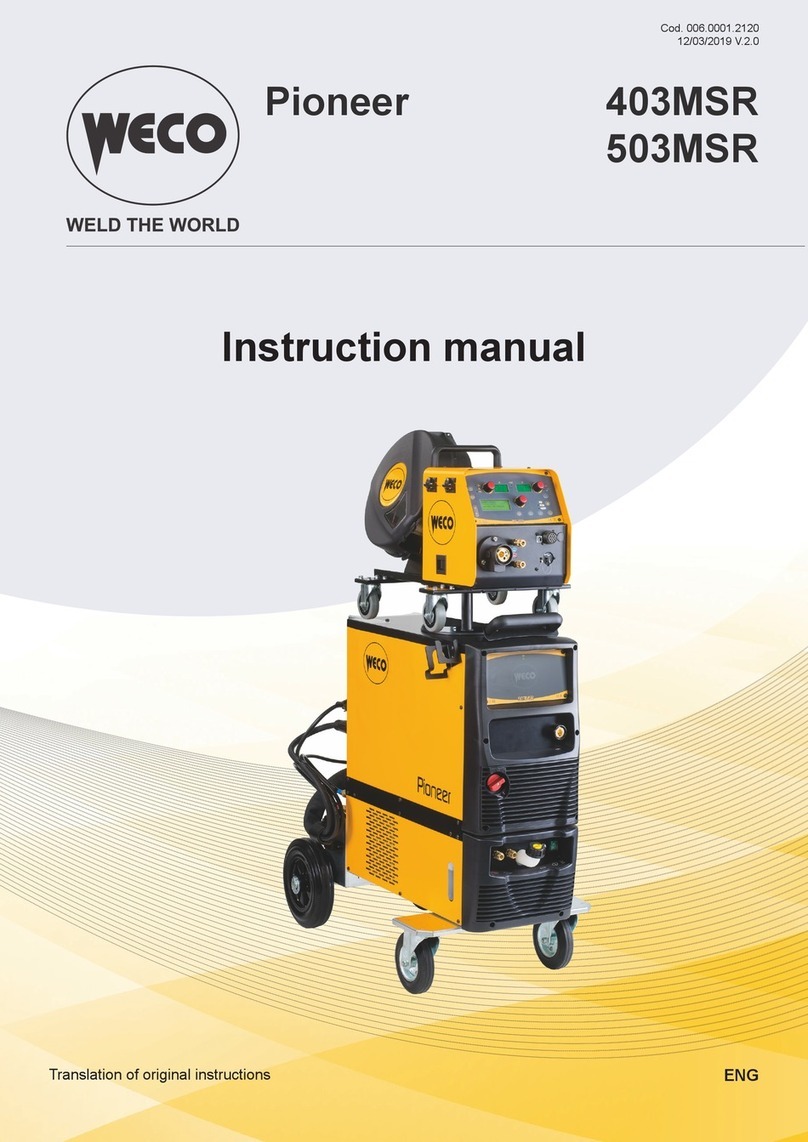
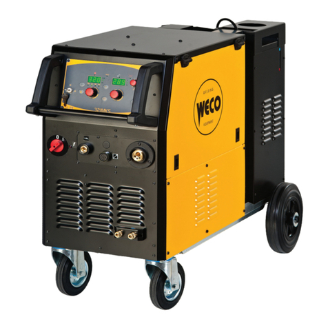
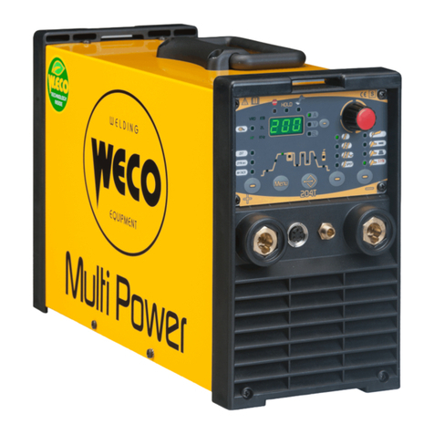
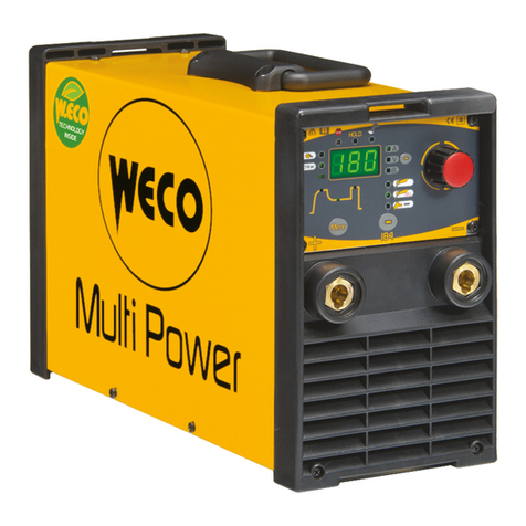
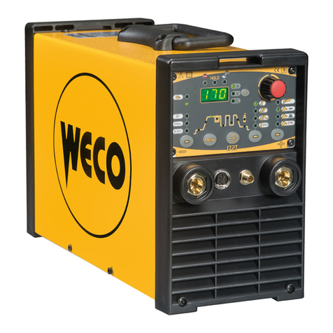
Weco Discovery 150TP-VRD User manual

Cod.006.0001.0415
30/08/2016 v2.1
ENGLISH
WECO srl
Via S. Antonio, 22 - BE VEDERE
36056 TEZZE SU BRENTA (VICENZA) ITA Y
Tel.+39 0424 561943 - Fax +39 0424 561944
www.weco.it - E-mail info@weco.it
Discovery 150TP
-
VRD
GB Instruction manual

Cod.006.0001.0415
30/08/2016 v2.1
ENGLISH
Discovery 150TP-VRD
2
/
12

Discovery 150TP-VRD
Cod.006.0001.0415
30/08/2016 v2.1
ENGLISH
3
/
12
CONTENTS
1
INTRODUCTION ........................................................................................................................................ 4
2
INST LL TION ......................................................................................................................................... 4
2.1
CONNECTIONS TO THE E ECTRICA MAINS NETWORK ....................................................................... 4
2.2
FRONT PANE .......................................................................................................................................... 4
2.3
REAR PANE ............................................................................................................................................. 5
2.4
PREPARING FOR MMA WE DING ............................................................................................................ 5
2.5
PREPARING FOR TIG WE DING .............................................................................................................. 6
3
COMMISSIONING ...................................................................................................................................... 7
3.1
USER INTERFACE .................................................................................................................................... 7
3.2
WE DING PARAMETERS .......................................................................................................................... 7
4
TECHNIC L D T .................................................................................................................................... 8
5
SP RE P RTS .......................................................................................................................................... 9
5.1
DISCOVERY 150TP-VRD ........................................................................................................................... 9
6
ELECTRIC L DI GR M ..........................................................................................................................11
6.1
DISCOVERY 150TP-VRD ..........................................................................................................................11

Cod.006.0001.0415
30/08/2016 v2.1
ENGLISH
Discovery 150TP-VRD
4
/
12
1INTRODUCTION
IMPORT NT!
This handbook must be consigned to the user prior to
installation and commissioning of the unit.
Read the "General prescriptions for use" handbook supplied
separately from this handbook before installing and
commissioning the unit.
The meaning of the symbols in this manual and the associated
precautionary information are given in the "General
prescriptions for use”.
If the "General prescriptions for use" are not present, it is
mandatory to reque
st a replacement copy from the manufacturer
or from your dealer.
Retain these documents for future consultation.
KEY
D NGER!
This pictogram warns of danger of death or serious injury.
This symbol identifies an action that occurs automatically as
a
result of a previous action.
This symbol identifies additional information or a reference to a
different section of the manual containing the associated
information.
NOTES
The figures in this manual are purely guideline and the images may
contain differences with respect to the actual equipment to which they
refer.
INTRODUCTION
Discovery 150TP-VRD is an advanced inverter power source
characterized by a robust and reliable industrial construction.
It is recommended for MMA welding and TIG DC applications
providing excellent arc characteristics.
Discovery 150TP-VRD is ideal for operations on site like basic
maintenance and building construction.
A built-in Total Protection Device saves the inverter components from
overvoltage and makes the unit suitable for use with unstable power
supply and motor-generators.
Factory optimized Hot Start, Arc Force and Anti Sticking allow an easy
and excellent quality welding using electrodes up to 3.25 mm
diameter.
In TIG DC, Pulse selection is included, making Discovery 150TP-VRD
unique in its range.
ift Start function guarantees arc ignition without damaging the
tungsten electrode.
2INST LL TION
D NGER!
Lifting and positioning
Read the warnings highlighted by the following symbols in the
“General prescriptions for use”.
2.1 CONNECTIONS TO THE ELECTRIC L M INS
NETWORK
The characteristics of the mains power supply to which the equipment
shall be connected are given in the section entitled “Technical data”
on page 8.
Connect/disconnect the various devices with the machine switched
off.
2.2 FRONT P NEL
1.
Positive pole welding socket.
2.
Negative pole welding socket.
2
1

Discovery 150TP-VRD
Cod.006.0001.0415
30/08/2016 v2.1
ENGLISH
5
/
12
2.3 RE R P NEL
1.
Warning ED for overcut protection triggering.
In case of over-voltage in the supply line, the supply to the power
source is cut off. The overcut protection protects electronic parts
of the machine against damage caused by voltage surges.
2.
Welding power source ON/OFF switch.
3.
Power cable.
Total length (including internal part): 3
.
0 m
Number and cross section of wires: 3 x 2
.
5 mm
2
Power plug type: Schuko
2.4 PREP RING FOR MM WELDING
1.
Set the welding power source ON/OFF
switch to “O” (unit de
-
energized).
2.
Plug the power cable plug into a mains socket outlet.
3.
Choose the electrode based on the type of material and thickness
of the workpiece to be welded.
4.
Insert the electrode in the electrode holder.
5.
Connect
the electrode holder cable to the welding socket based on
the polarity requested by the type of electrode used.
6.
Connect the plug of the ground clamp to the welding socket on the
basis of the polarity required.
7.
Connect the earth clamp to the workpiece being processed.
D NGER!
Electric shock hazard!
Read the warnings highlighted by the following symbols in the
“General prescriptions for use”.
8.
Set the welding power source ON/OFF switch to “I” (unit
powered).
9.
Select the following welding mode on the user interface: MMA
The system is ready to start welding.
Preparing for MMA (polarity to basic electrode)
1 2 3

Cod.006.0001.0415
30/08/2016 v2.1
ENGLISH
Discovery 150TP-VRD
6
/
12
2.5 PREP RING FOR TIG WELDING
1.
Set the welding power source ON/OFF switch to “O” (unit
de
-
energized).
2.
Plug the power cable plug into a mains socket outlet.
3.
Choose the electrode based on the type of material and thickness
of the workpiece to be welded.
4.
Insert the electrode in the TIG torch.
5.
Connect the torch plug to the weldi
ng socket on the basis of the
polarity required by the type of electrode in question.
6.
Connect the plug of the ground clamp to the welding socket on the
basis of the polarity required.
7.
Connect the earth clamp to the workpiece being processed.
8.
Set the welding power source ON/OFF switch to “I” (unit
powered).
9.
Select the following welding mode on the user interface: DC TIG
This model of welding machine has not been provided either with
the control for gas flow (solenoid valve) or with the torch button.
The system is ready to start welding.
LIFT- RC WELDING
1.
Open the torch valve to let the gas out.
2.
Touch the workpiece with the torch electrode.
3.
Slowly lift the torch to strike the arc.
The WE DING CURRENT reaches the preset
value.
4.
Quickly move the torch clear of the workpiece to extinguish the
welding arc.
5.
Close the torch valve to interrupt the gas flow.
Preparing for TIG (polarity for tungsten electrode)

Discovery 150TP-VRD
Cod.006.0001.0415
30/08/2016 v2.1
ENGLISH
7
/
12
3COMMISSIONING
3.1 USER INTERF CE
CODE
SYMBOL
DESCRIPTION
1
Overheating alarm
Indicates tripping of the welding power source thermal protection.
eave the unit running so that the overheated components cool as rapidly as possible.
When the unit has cooled, the welding power source will reset automatically.
-Make sure that the power required by the welding process is lower than the maximum rated power output.
-Check that the operating conditions are in compliance with the welding power source data plate specifications.
-Check for the presence of adequate air circulation around the welding power source.
2
This ED illuminates to confirm the presence of power on the output sockets.
3
ctive VRD signal
When lit this shows that the Voltage Reducing Device is active, reducing the voltage across the welding sockets.
This will happen within 2 seconds after the welding arc is broken to protect the welder from electric shock.
Full arc striking voltage will automatically be re-established when the welding circuit is re-established by touching the
electrode to the work-piece.
POT1
The potentiometer sets the value of the following parameter:
WE DING CURRENT
SE 1
The selector sets the welding mode.
MMA
PU SED DC TIG
TIG DC CONTINUOUS
3.2 WELDING P R METERS
P R METER
MIN
DEF ULT
M X
NOTES
WE DING CURRENT (MMA)
5 A
-
1
5
0 A
WE DING CURRENT (TIG)
5 A
-
150 A
PU SED CURRENT FREQUENCY
100 Hz
TIG only, set by the manufacturer.
HOT
-
START
50 %
Set by the
manufacturer.
ARC FORCE
50 %
Set by the manufacturer.

Cod.006.0001.0415
30/08/2016 v2.1
ENGLISH
Discovery 150TP-VRD
8
/
12
4TECHNIC L D T
Directives applied
Waste electrical and electronic equipment (WEEE)
Electromagnetic compatibility (EMC)
ow voltage ( VD)
Restriction of the use o
f certain hazardous substances
(RoHS)
Construction standards
EN 60974
-
1; EN 60974
-
10 Class A
Conformity markings
Equipment compliant with European directives in force
Equipment suitable in an environment with increased hazard of electric shock
Equipment compliant with directive WEEE
Equipment compliant with directive RoHS
Supply voltage
1 x 230 Va.c. ± 15 % / 50
-
60 Hz
Mains protection
16 A Delayed
Z
max
If this equipment is connected
to a public low voltage system, it is the responsibility of the
installer or user of the equipment to ensure, by consultation with the distribution network
operator if necessary, that the equipment may be connected.
Dimensions ( L x D x H )
310 x 120 x
215 mm
Weight
4.4 kg
Insulation class
B
Protection rating
IP23S
Cooling
AF: Air
-
over cooling (fan assisted)
Static characteristic MMA
Drooping characteristic
TIG
Drooping characteristic
Current and voltage adjustment range MMA 5 A / 20.2 V - 150 A - 26.6 V
TIG 5 A / 10.2 V - 150 A - 16.0 V
Welding current / Working voltage
MMA
30
% (40° C)
150 A
-
26
.6 V
60 % (40° C)
110 A
-
24.4 V
100 % (40° C)
100 A
-
24.0 V
TIG
35 % (40° C)
150 A
-
16.0 V
60 % (40° C)
115 A
-
14.6 V
100 % (40° C)
100 A
-
14.0 V
Maximum input power
MMA
3
0
% (40° C)
6.2
kVA
60 % (40° C)
4.5 kVA
100 % (40° C)
3.9 kVA
TIG
35 % (40° C)
4.1 kVA
60 % (40° C)
3.1 kVA
100 % (40° C)
2.5 kVA
Maximum supply current
MMA
3
0
% (40° C)
2
6.8
A
60 %
(40° C)
19.2 A
100 % (40° C)
17.0 A
TIG
35 % (40° C)
17.8 A
60 % (40° C)
13.2 A
100 % (40° C)
10.9 A
Maximum effective supply current
MMA
3
0
% (40° C)
14.
6
A
60 % (40° C)
14.9 A
100 % (40° C)
17.0 A
TIG
35 % (40° C)
10.5 A
60 % (40°
C)
10.2 A
100 % (40° C)
10.9 A
No-load voltage (U
0
)
MMA
94 V
TIG
94 V
Reduced no-load voltage (U
r
)
MMA
9
V
TIG
9
V

Discovery 150TP-VRD
Cod.006.0001.0415
30/08/2016 v2.1
ENGLISH
9
/
12
5SP RE P RTS
5.1 DISCOVERY 150TP-VRD

Cod.006.0001.0415
30/08/2016 v2.1
ENGLISH
Discovery 150TP-VRD
10
/
12
N°
CODE
CODICE DESCRIPTION
1
005.0001.0002
BE T
2
011.0000.0021
UPPER COVER
3
015.0001.0001
HEAT SINK =107mm
4
015.0001.0002
HEAT SINK =50mm
5
050.0006.0001
POWER BOARD
6 012.0001.0000 INTERNA FRAMEWORKS
7
050.0001.0110
OGIC FRONT PANE
8
013.0015.0849
FRONT ABE
9 021.0001.1022 FIXED SOCKET 200A
10
012.0001.0150
FRONT P ASTIC PANE
11
014.0002.0008
KNOB
12 012.0001.0007 OWER COVER
13
040.0003.1080
TERMA SWITCH
14
045.0006.0002
COPPER BRACKET
15 015.0001.0003 HEAT SINK =75mm
16
032.0002.2003
DIODE
17
050.0001.0043
DOUB ER
-
OVERCUT
BOARD
18
003.0002.0001
FAN
19
011.0006.0031
HAND E
20
010.0006.0004
REAR P ASTIC PANE
21
045.0000.0007
CAB E C AMP
22 045.0002.0001 SUPP Y CAB E
23
040.0001.0004
TWO
-
PO E SWITCH
24
010.0007.0005
P ANAR TRANSFORMER
25 045.0005.0003 SHUNT

Discovery 150TP-VRD
Cod.006.0001.0415
30/08/2016 v2.1
ENGLISH
11
/
12
6ELECTRIC L DI GR M
6.1 DISCOVERY 150TP-VRD

Cod.006.0001.0415
30/08/2016 v2.1
ENGLISH
Discovery 150TP-VRD
12
/
12
Table of contents
Other Weco Inverter manuals

Weco
Weco Cruiser 402 T User manual

Weco
Weco Multi Power 204T User manual

Weco
Weco Pioneer 403MSR User manual

Weco
Weco Discovery 162T User manual

Weco
Weco Discovery 172T User manual

Weco
Weco Pioneer Pulse 321MKS User manual

Weco
Weco Pioneer Pulse 321MKS User manual

Weco
Weco ESS XTE Series User manual

Weco
Weco Multi Power 184 User manual
Popular Inverter manuals by other brands

Sofar
Sofar CXAU0655BVS user manual

Pylontech
Pylontech P-Combiner-HV-3 instruction manual

Studer
Studer HPSI Series User and installer handbook

CSE Universe
CSE Universe FRN0.75F1?-2J instruction manual

Sunways
Sunways STT-50KTL user manual

Power One
Power One Aurora PVI-3.0-TL-OUTD Installation and configuration manual