A8051 Development Board User Guide ER-DBT018-3
URL: www.buydisplay.com Document Name: ER-DBT018-3 User Guide-Rev1.0 Page: 8 of 15
buydisplay.com
EastRisingR
6. HOW TO MAKE A CUSTOM DEMONSTRATION
By using the software of LCD Font Maker or Image2LCDand ISP(In System Programming to customize the
demonstration that includes your own bitmap images, personalized fonts, symbols, icons and burn
sketches. The large capacity of the MicroSD card allows you to store more fonts or images. We also
prepare the demo code, interfacing document (download from each product page) and schematic MCU
datasheet (download from each 8051 microcontroller developmentboard page) for your further study.
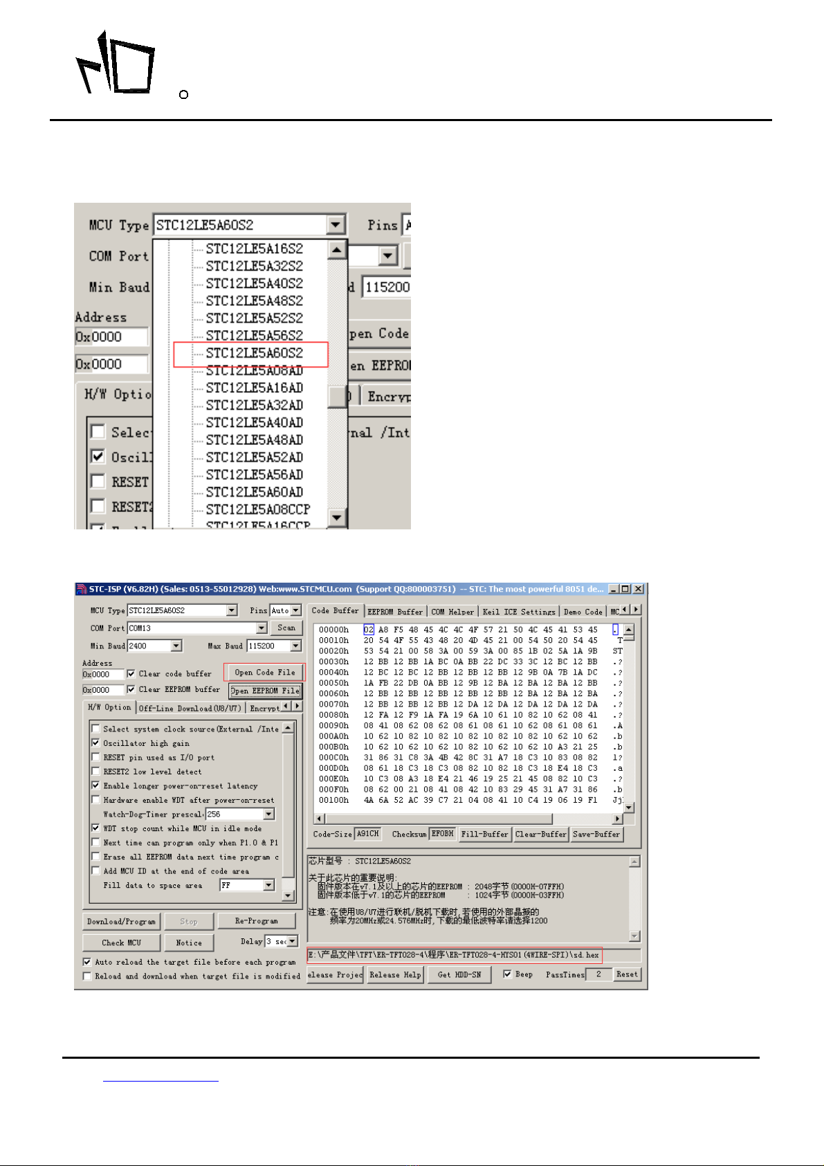
7. METHODS FOR USING IN SYSTEM PROGRAMMING
7-1 Hardware Preparation
7-1-1 Please power off the development board,
7-1-2 No power supply is connecting with 8051 development board,
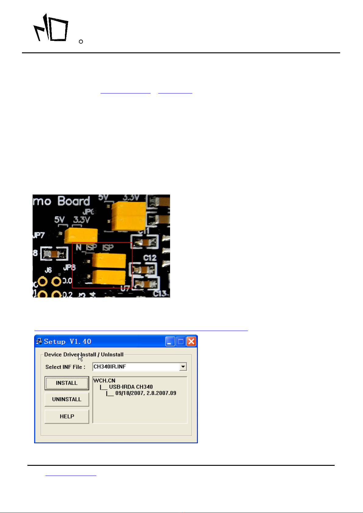
7-7-3 The jumpers on JP8 is on ISP position as below image shows
7-2 Install the USB to RS232 Driver
http://www.buydisplay.com/download/software/USB-TO-RS232-DRIVER.rar