EasyHeat TSRP Series User manual

DESCRIPTION
The TSRP Standard Power Connection Kit is for use with
all versions of Easy Heat self regulating cables for pipe
tracing applications. It is also compatible with any heater
cable smaller than 0.44" (11mm) in diameter.
Note: This kit contains materials to connect power to
either (1) or (2) heater cables through a common stand-
off and junction box.
TSRP Power Connection Kit Installation Instructions
KIT CONTENTS
1 Junction Box 2 Power Terminations
2 Warning Labels 1 Box Adapter
1 Terminal Block 1 Gasket
1 Conduit Locknut 1 Tube of Silicone
1 Sealing Grommet 2 End Seals
1 Stand-off 2 Pipe Clamps
1 Uninsulated Splice Connector
aWARNING!
• Article250oftheNationalElectricalCoderequiresallmetallicconduitandfittingsterminatingatthe
junctionboxtobeeffectivelygroundedbyapprovedmeans.
• Article427oftheNationalElectricalCoderequiresthatallheatersshallhavegroundedmetalcoverings
andground-faultprotection.
• Ifnuisancetrippingofgroundfaultbreakersoccursduetocondensationinthejunctionbox,electrical
connectionsshouldbemoisture-proofedbysuitablemeans!
• Minimuminstallationtemperature-40°C(-40°F).
14036-001 Rev. 3 ©2010 EasyHeat
*ITEMSNOTINCLUDEDINKIT
SILICONE
Power Termination
Terminal Block
Junction Box
*Heater Cable
Conduit Locknut
Gasket
Box Adapter
Sealing Grommet
Stand-off
End Seal
*Heater Cable — Shown at
Top pf Pipe for Clarity Only
Pipe Clamps
Label
Box Cover Gasket
Box Cover
*Conduit Con-
nector
*Flex
Conduit
*Conduit Power Supply
*Low Point Drain Fitting
(If Required)

CABLE INSTALLATION
Install cable on pipe in the preferred/recommended
orientation(s), in either straight or spiral method ac-
cording to pipe heat requirements. Secure cable every
24" using 3/4" w. fiberglass tape, NST-2 (or equiva-
lent).
2 TSRP POWER CONNECTION KIT Installation Instructions
CABLE TERMINATION
1. Terminate end of cable per end seal
directions, Page 4.
2. Mark pipe where stand-off will be
mounted and cut cable 10" beyond
mark.
3. Push heater cables through the bot-
tom opening of stand-off, allowing 6"
(152mm) tail to protrude from threaded
end.
4. Place stand-off on the pipe at 4 o’clock
or 8 o’clock position and fasten with
pipe clamps.
5. Slide the sealing grommet, beveled
end first, over the heater cable and
position inside stand-off throat.
6. Apply silicon around the heater cable
sufficient to fill all voids in sealing
grommet.
7. Slide the box adapter over heater cable
and tighten securely to stand-off.
8. Prepare heater cable for power
termination according to Cable
Stripping Procedure, Page 3.
9. Connect power in accordance
with Power Connection Procedure,
Page 5. aWARNING!
Donotplacepipeclampsover
theheatercable.
CABLE CONTROL
The Easy Heat SR Cables for pipe tracing applications
can be controlled in several different ways. The sim-
plest control method is to connect power to the cable
at all times; the self regulating characteristic of the
cable will ensure that cable power is reduced if heat
is not required on the pipe. Alternately, a thermostat
can be used to control the cable and maintain the pipe
at an appropriate temperature. Contact Easy Heat for
additional information.
*ITEMS NOT INCLUDED IN KIT
10”
(254mm)
*Fiberglass Tape Stand-off
Sealing Grommet
Box Adapter
Power Termination
Pipe Clamps
8 o’clock 4 o’clock

TSRP POWER CONNECTION KIT Installation Instructions 3
the outside
of each bus
wire.
12. Starting at
the end, pull
each bus
wire away
from the
core mate-
rial.
13. Remove exposed core material.
14. Cut .25" (6mm)
off the end
of each bus
wire.
CABLE STRIPPING PROCEDURE
For cables without overjacket (braid only), proceed
directly to step 4.
1. Lightly cut around
heater overjacket 5"
(127mm) from the end.
Bend cable to break
overjacket.
2. Lightly cut overjacket
up the center between
first cut mark and the cable
end. Bend cable to break the
overjacket.
3. Remove overjacket from
the heater cable.
4. Move braid back toward the
overjacket, creating a bulge.
(For cables without overjacket, ap-
ply a ring of electrical tape 5" from end
of cable, then
move braid
back toward
tape, creating a
bulge.)
8. With braid prepared as shown, lightly cut
around heater jacket 4" (102mm) from the end.
Bend cable to break outer jacket.
9. Lightly cut the
outer jacket up the
center between the
first cut mark and the
cable end. Bend cable
to break outer jacket.
10. Remove the jacket from
the heater cable.
11. Shave the core material from
aWARNING!
Donotcutornickbraid.
5. At the bulge, separate the braid to make an
opening.
6. While bending the
heater cable, work it
through the braid opening.
7. Pull the braid tight
.
4.5" (114mm)
4"
(102mm)
aWARNING!
Donotcutornickwires. (continued on next page)

aWARNING!
• Buswiresmustnottouchorcrosswhileinserting
intopowertermination/endseal.
• Onlypowerterminations/endsealsspecifically
approvedforthevendor’sstyleandtypeof
heatercablemustbeused.
15. Insert bus wires into power termination.
16. Squeeze power termination ferrule open
and fill opening with silicone. (The sili-
cone will set up in about 30minutes with
a complete cure after 24 hours.)
17. Push power termination to overlap jacket.
18. Trime bus wires to exposure length
shown.
apply silicone
here
0.5" (13mm)
END SEAL
1. Remove 0.5" of overjacket exposing the
braid, then remove the 0.5" (13mm) of
exposed braid.
2. Make a 0.4" (10mm) cut at the end of the
heater cable.
3. Squeeze end seal and fill with silicone.
(The silicone will set up in about 30 min-
TSRP POWER CONNECTION KIT Installation Instructions 4
utes with a complete cure after 24 hours.)
4. Push end seal over the heater cable.
Apply silicone here

TERMINALBLOCKCONNECTION
Ground Braid
Power Leads Heater
Cable
5 TSRP POWER CONNECTION KIT Installation Instructions
POWER CONNECTION
1. Place gasket on the box adapter.
2. Position the junction box on the box adapter and
secure it with the conduit locknut.
3. Connect bus wires and ground braid from all
heater cables to the terminal block. See diagram
below.
4. Apply silicone at point braid leaves the overjack-
et.
5. Push all wires, cables and the terminal block inside
junction box.
6. Place the box cover and box cover gasket onto
the junction box, and install warning label as re-
quired.
Terminal Block
Ground Wire
Ground Braid
Power Termination
Conduit and Drain not included in kit.
(Must be positioned lower than junction box.)

GENERAL INFORMATION
Easy Heat TSR Cable connection kits are provided in nonme-
tallic NEMA 4X enclosures for use in pipe tracing applica-
tions in ordinary locations and Division 2 hazardous areas
when used with Easy Heat TSR Cable. These kits contain all
necessary components to terminate/connect TSR Cable and
any associated power supply.
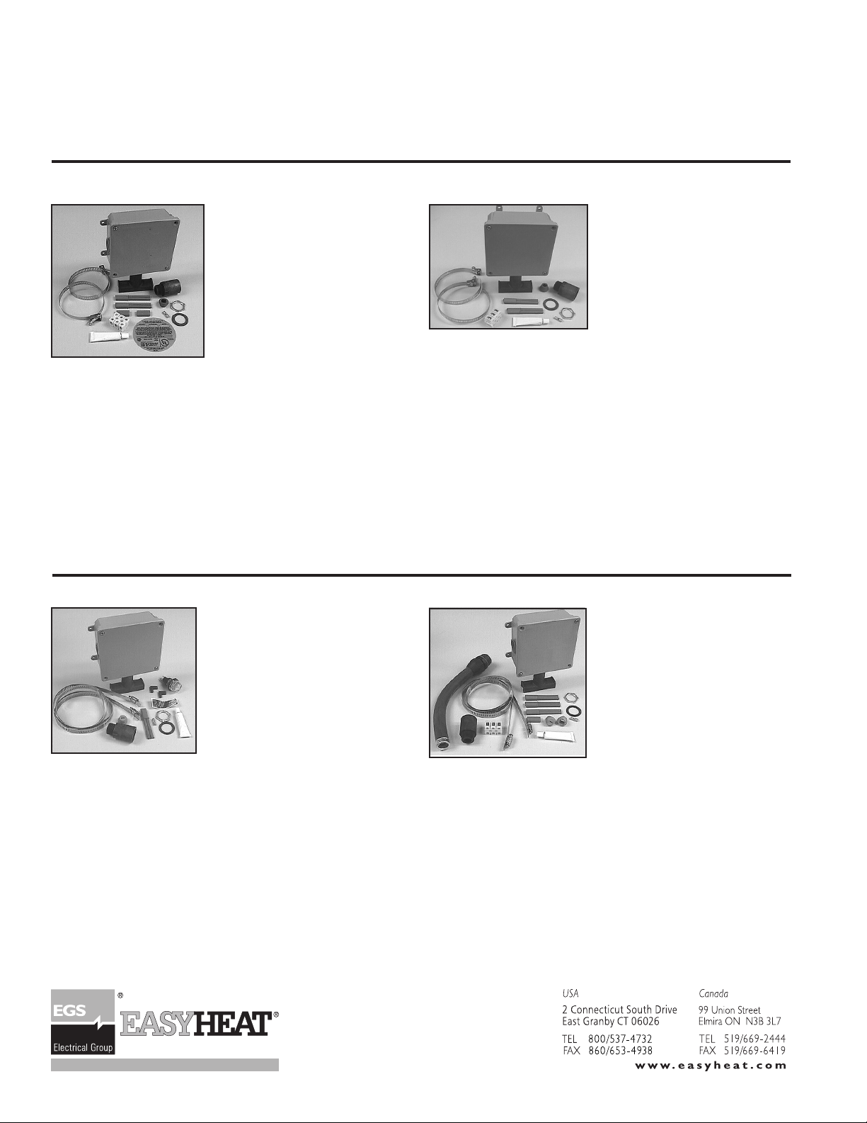
TSRP POWER CONNECTION KIT TSRS SPLICE KIT
TSR Cable Connection Kits Selection Guide
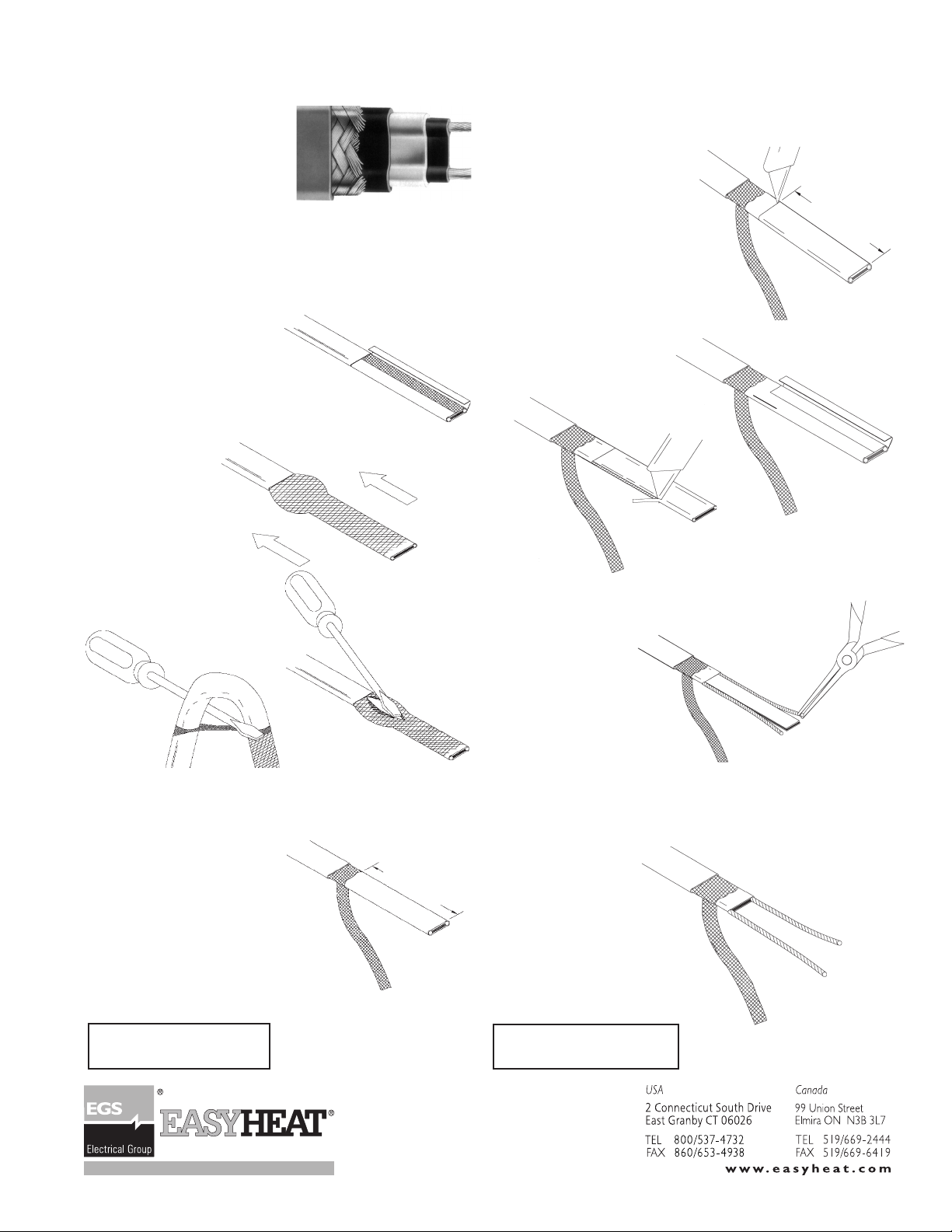
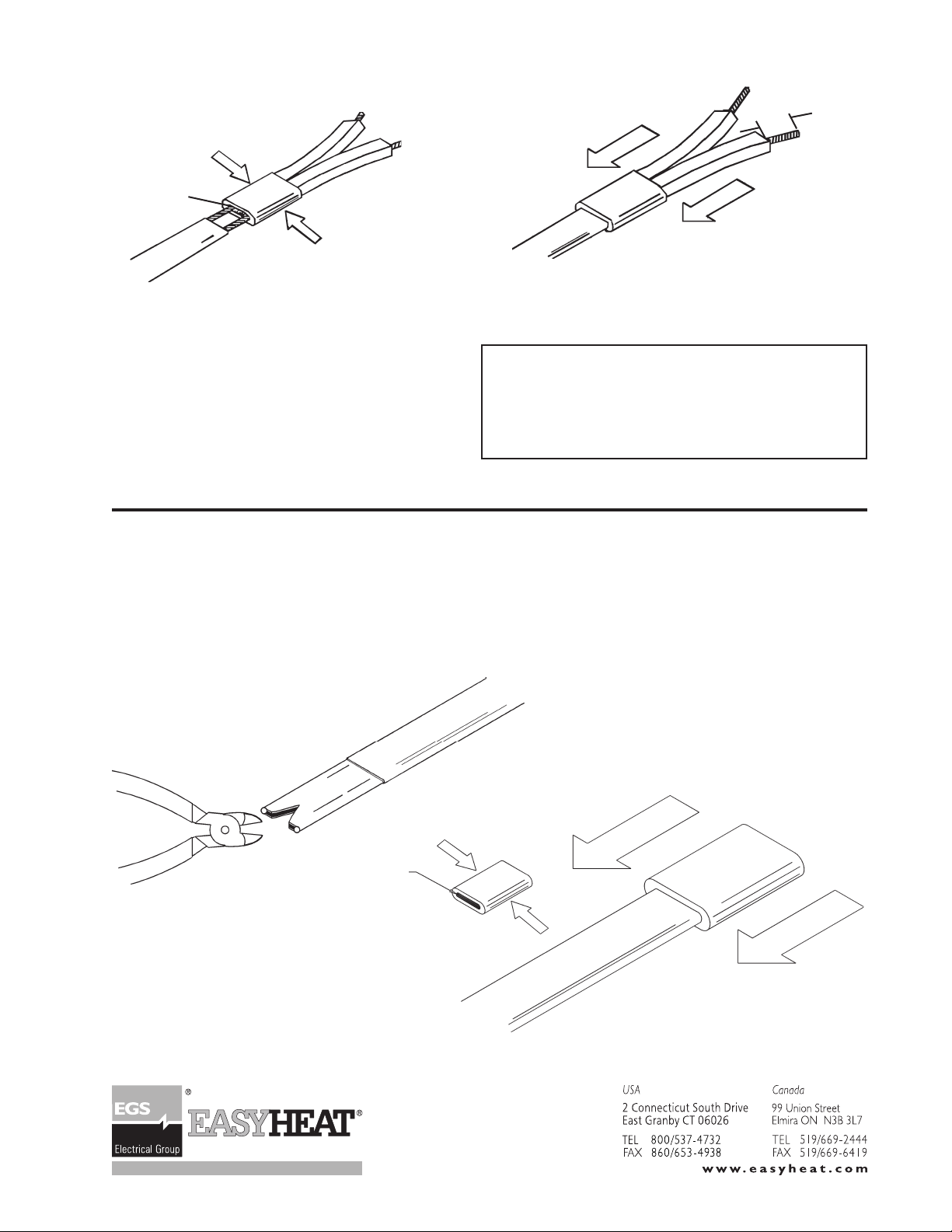
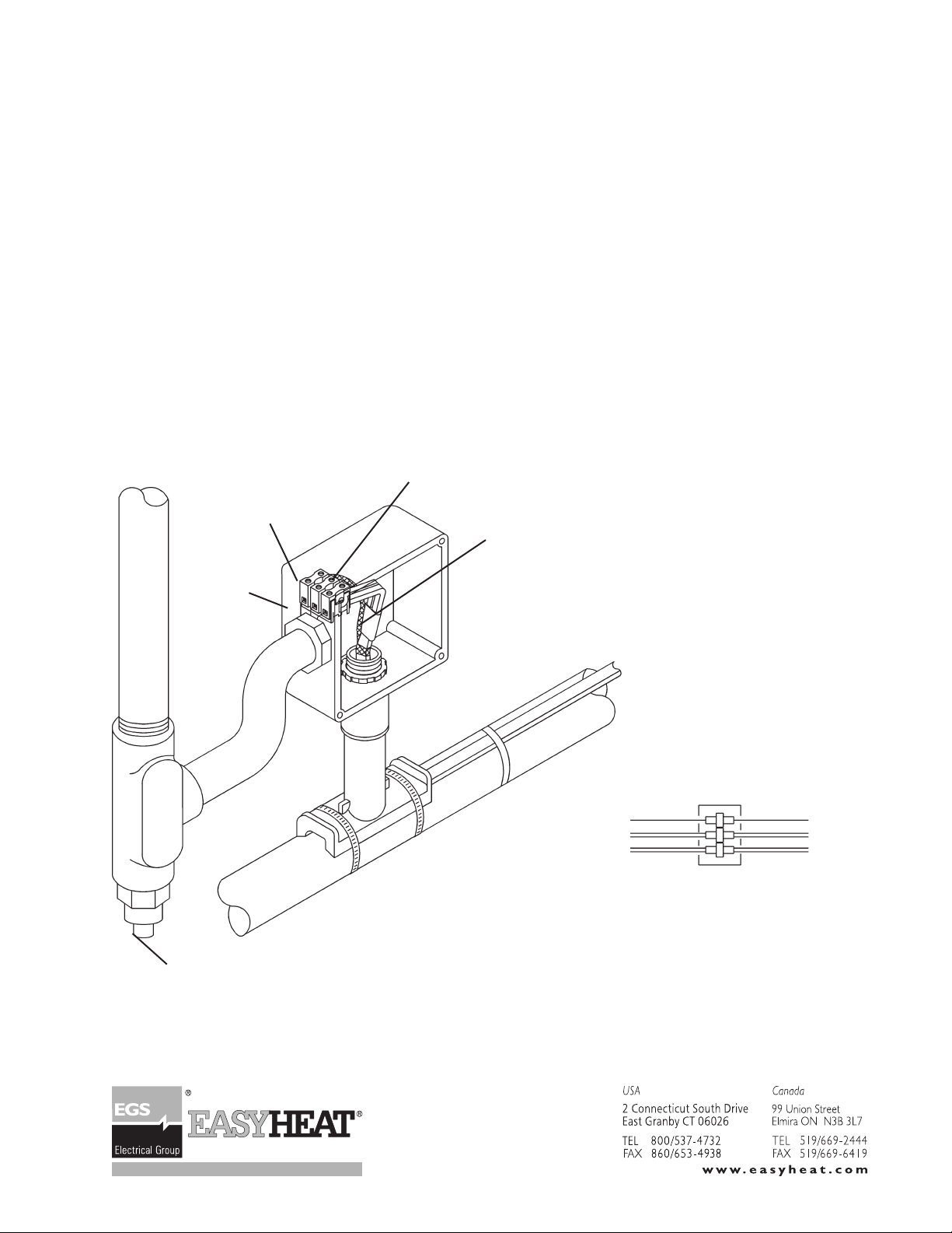
6 TSRP POWER CONNECTION KIT Installation Instructions
TSRL PILOT CIRCUIT KITS TSRT TEE SPLICE KIT
The TSRP Power Connection Kit
is suitable for connecting up to
two heating cables to customer
supplied power wiring. Seals
for up to 2 cable ends are also
provided.
Models: TSRP3, TSRP12,
TSRP20.
Kit Contents
1 Universal Base, Box Adapter, Sealing Gasket, and Lock-
nut Assembly
1 Nonmetallic Junction Box with Cover and Sealing Gas-
ket
1 Sealing Grommet
2 Power Terminations
2 Cable End Seals
1 Tube Adhesive Sealant
1 3-point Floating Terminal Block
1 Ground Connection Splice
2 Stainless Steel Pipe Clamps: TSRP3, 3"; TSRP12, 12";
TSRP20, 20"
1 Label
Kit Contents
1 Universal Base, Box Adapter, Sealing Gasket and Lock-
nut
1 Nonmetallic Junction Box with Cover and Sealing Gas-
ket
1 Sealing Grommet
2 Power Terminations
1 Tube Adhesive Sealant
1 3-point Floating Terminal Block
1 Ground Connection Splice
2 Stainless Steel Pipe Clamps: TSRS3, 3"; TSRS12, 12";
TSRS20, 20"
1 Label
The TSRS Splice Connection
Kit is designed for connecting
two heating cables together in
an in-line splice configuration.
Models:TSRS3,TSRS12,TSRS20.
Kit Contents
1 Universal Base, Box Adapter, Sealing Gasket, and Locknut
Assembly
1 Nonmetallic Junction Box with Cover and Sealing Gasket
1 Sealing Grommet
1 Power Termination
1 Tube Adhesive Sealant
1 Ground Connection Splice
2 Stainless Steel Pipe Clamps for pipe size up to 12"
1 Pilot Light Assembly
120 Volt model: TSRL112; 208 Volt model: TSRL812
240 Volt model: TSRL212; 277 Volt model: TSRL712
1 Label
The TSRL Pilot Light Kits are
designed as end-of-circuit indicating
light assemblies utilizing low temper-
ature neon lamps. Kits are available
for 120V, 208V, 240V and 277V op-
eration.Installation of pilot light tail kit
ensures that power is applied to the
entire cable, and that the heating
cable can be expected to operate as
designed. Note that if a thermostat
controls power to the cable, the pilot
light will operate ONLY when the
cable is energized. Kit Contents
1 Universal Base, Box Adapter, Sealing Gasket and Lock-
nut Assembly
1 Nonmetallic Junction Box with Cover and Sealing Gasket
1 Watertight Connection Fitting with 12" Hi-Temp Flexible
Tubing
1 Sealing Grommet
3 Power Terminations
2 Cable End Seals
1 Tube Adhesive Sealant
1 3-point Floating Terminal Block
1 Ground Connection Splice
2 Stainless Steel Pipe Clamps: TSRT3, 3"; TSRT12, 12";
TSRT20, 20"
1 Label
The TSRT Tee Connection Kit is
designed for connecting heating
cables in a tee splice configura-
tion. Seals for up to 2 cable ends
are also provided.
This manual suits for next models
16
Table of contents