Version v1.0 –February 15, 2015 www.easylibatteries.com 5
Imprimé sur papier 100% recyclé
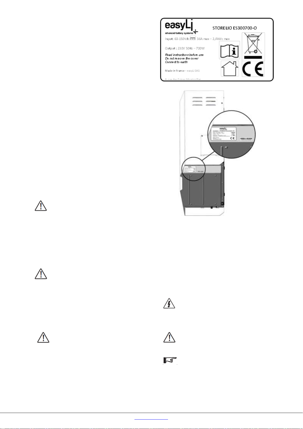
3.2.2.Battery box
Figure 3
1. Cover
2. Battery
3. Power connector
4. Communication connector
3.3. Operating principles
Photovoltaic energy from PV panels is converted into
alternating current and feed in a dedicated house grid
powered by Storelio off-grid. Excess current is temporary
stored into the Lithium battery for later release.
Dedicated grid is made of electrical devices which
cumulated power must be lower than the maximum
authorized power of Storelio off-grid. Only this dedicated
grid will be powered by Storelio off-grid.
DANGER!
Never connect the dedicated grid to the main
house grid powered by the distribution grid. It
can cause irreversible damages not covered by
the warranty.
When electrical devices of the dedicated grid
are requiring more than the maximum power of
Storelio off-grid, the system will reach the
« overload » state and the electrical devices will
not be powered anymore. It is mandatory to
unplug some devices to come back to a total
power lower than the authorized one.
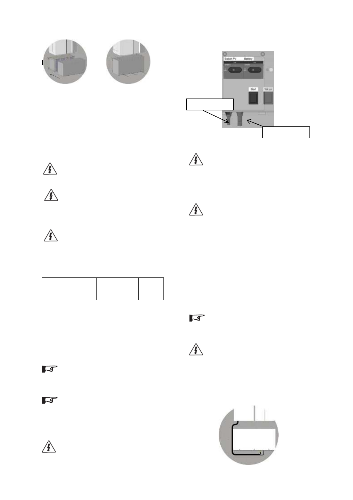
Storelio off-grid is equipped with an AC input. This input
must be connected after the house main current breaker
(see Figure 4). The available power of the AC input line
must be equal to the maximum power of Storelio off-grid.
Refer to chapter “Technical data”.
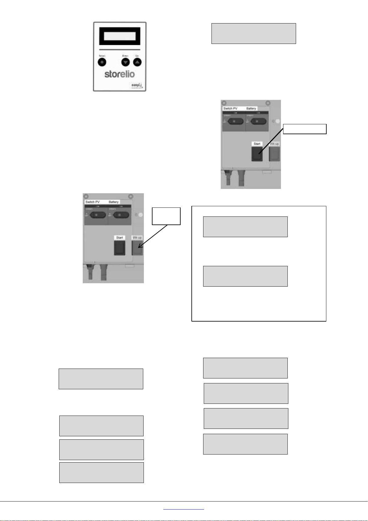
Figure 4
1. PV Input (+/-)
2. Battery box connection (provided cables)
3. AC Input
4. AC output (dedicated grid)
5. Main house breaker, connected to the distribution grid
Two operating modes are available:
« off-grid » mode
When the Lithium battery capacity level is over 0%, the
dedicated gridis powered by Storelio off-grid, from the solar
panels or the Lithium battery. This is the “off-grid” mode.
« grid » mode
When the Lithium battery is discharged and its level displays
0%, the dedicated grid is powered by the AC input line. This
is the “grid” mode.
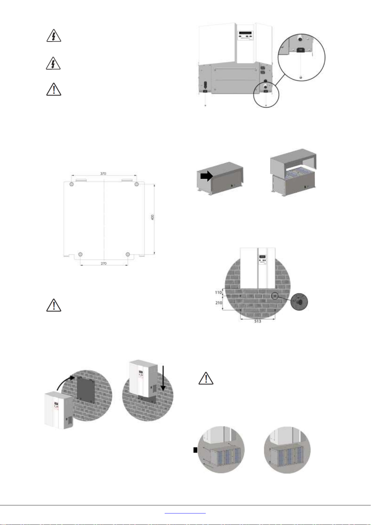
3.4. Environment requirements and installation
precautions
Storelio off-grid must be mounted indoor
Do not expose Storelio off-grid to any direct
sunlight or any source of heat or excessive dust.
Storelio off-grid must not be accessible to
children.
- Storelio off-grid must be installed in a dry area, away from
rain. Do not let water penetrate inside Storelio off-grid.
- Mount Storelio off-grid vertically. The mounting surface
must be able to withstand Storelio off-grid weight (up to 35
kg).
- Storelio off-grid is heavy. Make sure to handle it with 2
persons while mounting it onto the wall plate.
DANGER!
In case of drop or significant impact marks on
Storelio off-grid, do not follow on the installation
and do not attempt to repair Storelio off-grid.
Contact your easyLi authorized dealer.
- Storelio off-grid must be installed with 20 cm vertical and
horizontal clearance.
- Ambient temperature is 0°C/+40°C
- Recommended operating temperature is +5°C/+25°C
Never apply a DC input voltage higher than
specified. This causes permanent damage to
Storelio off-grid not covered by the warranty.
3.5. Lightning protection
In solar photovoltaic installations, precautions must be
taken to avoid damages from lightning surge. Storelio off-
grid is not equipped with surge protection. Make sure to
comply with local applicable regulations. The use of an
external photovoltaic surge protection from lightning may be
required. Storelio off-grid damages caused by lightning are
not covered by the warranty.
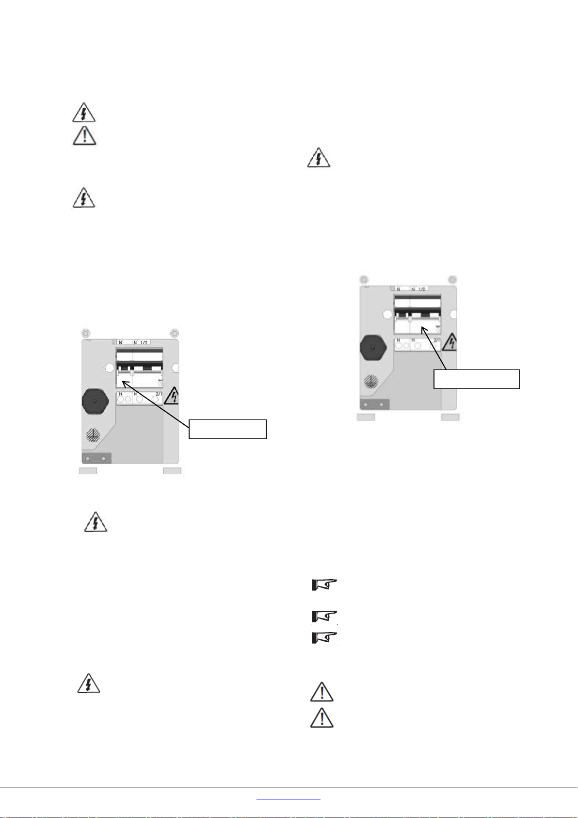
4. INSTALLATION
DANGER!
Switch OFF all AC 230V electrical sources before
starting any installation work.