Best Power KDE200A User manual

Preface
This manual provides you with relevant instructions and precautions for installation,
wiring, function parameter setting, routine maintenance, troubleshooting and troubleshooting
of the inverter.
In order to fully utilize the functions of the product and ensure the safety of users and
equipment, please read this manual carefully before using the inverter. Improper use may
cause the inverter to operate abnormally, malfunction, reduce the service life, and even
cause equipment damage, personal injury and other accidents!
Please pay special attention to the following safety precautions when handling this
product.
Please ensure to turn off the power when wiring.
The inverter must be properly grounded.
The AC power cord must never be connected to the inverter output terminals
U, V, W.
There is a high voltage circuit inside the inverter. It is strictly forbidden to
touch the internal parts by hand.
Only qualified electricians can install, wire, repair and repair the inverter.
Install the inverter in a suitable environment to prevent direct exposure to
high temperatures and sunlight, and to avoid splashing of moisture and water
droplets.
Please perform at least five minutes after the power is turned off during
inspection and maintenance.
Never modify the parts or circuits inside the inverter by yourself.
Do not test the voltage inside the inverter.
This series of products cannot be used in situations that endanger personal
safety.

Contents
Contents
Chapter 1 PoductInformation.................................................. 1
1-1 Safely Information................. ...... ...... .... ........ ...................................1
1-2 Name plate............................................................................................1
1-3 Technical Specifications.........................................................................5
Chapter 2 Installation of frequency inverter.......................... 6
2-1 Installation environment.........................................................................6
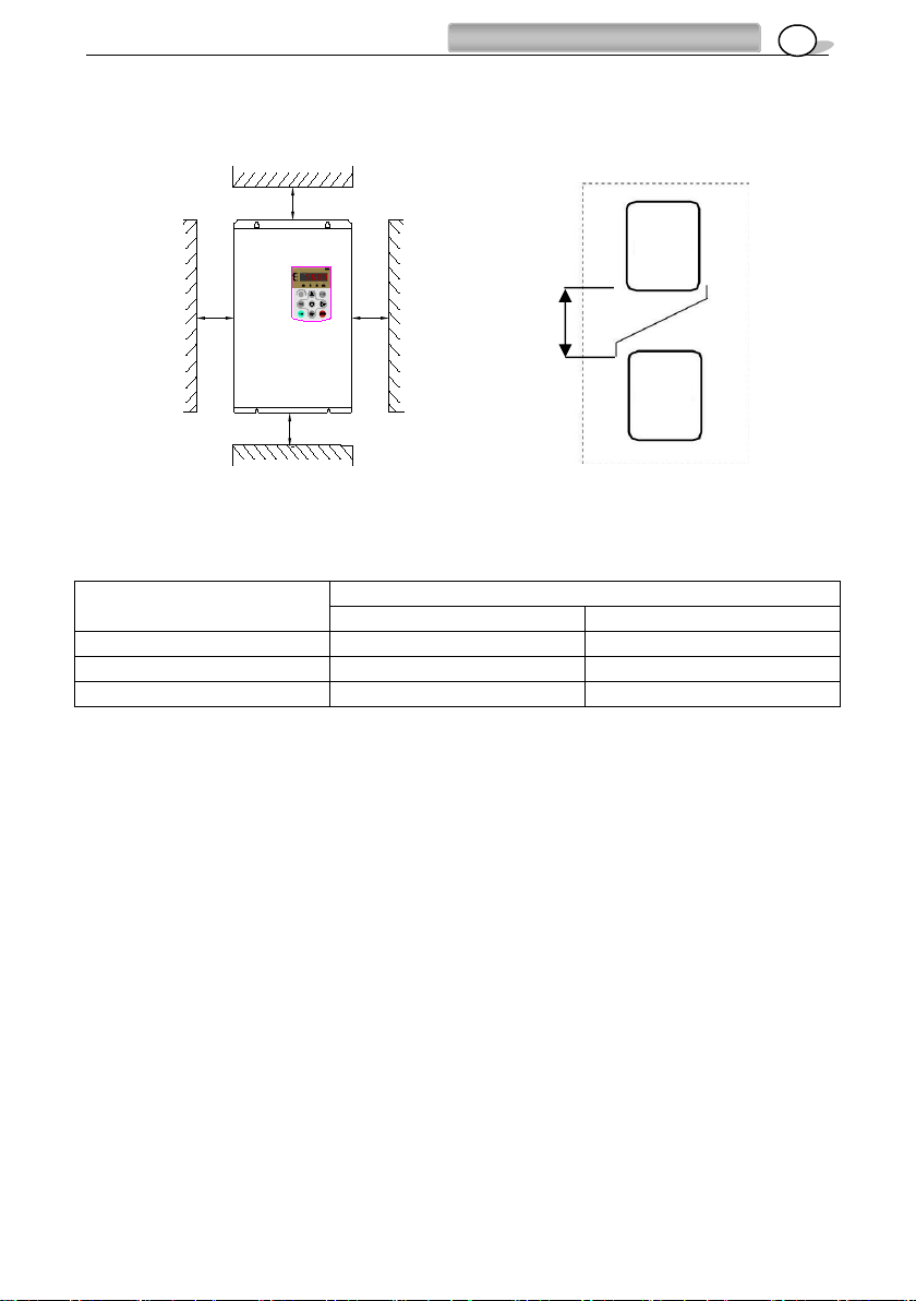
2-2 Installation direction and space..............................................................6
Chapter 3 Wiring.........................................................................8
3-1 Peripheral device connection..................................................................8
3-2 Standard wiring diagram.........................................................................9
3-3 Main circuit terminal description..............................................................10
3-4 Control circuit terminal description..........................................................12
Chapter 4 Keyboard operation..................................................14
4-1 Description of the keyboard panel..........................................................14
4-2 Function code modification, view instructions.........................................15
Chapter 5 Function Code...........................................................18
5-1 Standard function code...........................................................................18
5-2 Monitoring parameter .............................................................................48
Chapter 6 Parameter instruction................................................49
Group P0 Basic function group......................................................................49
Group P1 Motor 1 parameter.........................................................................57
Group P2 Vector control parameter...............................................................60
Group P3 V/F control parameter....................................................................63
Group P4 Input terminal.................................................................................69
Group P5 Output terminal..............................................................................80
Group P6 Start/Stop Control Parameters......................................................86
Group P7 Keypad display..............................................................................90
Group P8 Auxiliary Functions........................................................................93
Group P9 Fault and Protection......................................................................103
Group PA Process Control PID Function......................................................111
Group PB Swing Frequency, Fixed Length and Count.................................116

Contents
Group PC Multi-reference and simple PLC.................................................118
Group PP Password Setting....................................................................... 123
Group A0 Torque Control Function.............................................................124
Group A5 Control Optimization Parameters............................................... 125
Group A6 AICurve setting........................................................................... 127
Group AC AIAO correction.......................................................................... 129
Chapter 7 Fault Diagnosis and Solution...................................132
7.1 Fault Alarm and Countermeasures.......................................................132
7.2 Common Faults and Solutions............................................................. 138
Chapter 8 Repair and maintenance...........................................141
8-1 Repair and Maintenance.......................................................................141
8-2 Inspection and replacement of consumable parts.................................142
8-3 storage...................................................................................................142
8-4 Warranty of inverter................................................................................143
Chapter 9 Appendix.....................................................................144
Appendix A Communication protocol............................................................144
Appendix B Brake resistor selection list.........................................................155
Appendix C Inverter dimensions and installation dimensions.... ………….....156

Chapter 1、Product information
1
MODEL:XXXX - 7.5 G – T 4
Product
series
Power
7.5:7.5KW
Type
G:heavy duty
P:light duty
Phase
S: 1PH
T: 3PH
Voltage
2: 220V
4: 380V
6: 660V
Chapter 1 Production information
1-1 Inspection
Each inverter is subjected to strict quality control before being shipped from the factory, and
is made of enhanced anti-collision packaging. After the customer unpacks, please check the
following items:
Check if the inverter is damaged during transportation.
Check the package for instructions (with certificate and warranty card).
Check the inverter nameplate and confirm that it is the product model you
ordered.
If you ordered any option for the drive, please check to confirm.
1-2 Name plate
MODEL : XXXX-7.5G-T4
POWER : 7.5KW
INPUT : 3PH 380V±15% 50/60Hz
OUTPUT: 0-380V 0-500Hz 17A
Bar code
3 1 4 0 2 0 0 2 0
Model
Power
Input current
Output current
Product code
Product model description:

Chapter 1、Product information
2
1-3 Specification of lnverter
rated
power
kw
0.7
1.5
2.2
0.7
1.5
2.2
4
5.5
7.5
11
15
18.5
22
30
Output
Current
A
5
7
11
2.5
3.7
5.1
9
13
17
25
32
37
45
60
Rated
Voltage
V
1ph 220V
3ph 380V
Rated
power
kw
37
45
55
75
90
110
132
160
185
200
220
250
280
315
Output
current
A
75
90
110
150
176
210
250
300
340
380
415
470
520
600
Rated
voltage
V
3ph 380V
Item
Specifications
Standard
functions
Maximum frequency
Vector control:0~500Hz V/F control:0~500Hz
Carrier frequency
0.5kHz~16kHz (The carrier frequency is automatically
adjusted based on the load features.)
Input frequency
resolution
Digital setting: 0.01 Hz
Analog setting: maximum frequency x 0.025%
Control mode
Sensor-less flux vector control (SFVC)
Closed-loop vector control (CLVC) (+PG Card)
Voltage/Frequency (V/F) control
Startup torque
0.5Hz/150%(SVC);0Hz/180%(FVC)
Speed range
1:100 (SVC)
1:1000 (FVC)
Speed stability accuracy
±0.5%(SVC)
±0.02%(FVC)
Torque control accuracy
±5%(FVC)
Overload capacity
G type: 60s for 150% of the rated current, 3s for 180% of
the rated current
P type: 60s for 120% of the rated current, 3s for 150% of
the rated current
Torque boost
Auto boost;
Manual boost: 0.1%~30.0%

Chapter 1、Product information
3
V/F curve
Straight-line V/F curve
Multi-point V/F curve
N-powerV/F curve (1.2-power, 1.4-power, 1.6-power, 1.8-
power, square)
V/F separation
2 types: complete separation; half separation
Acceleration/deceleration
curve
Straight-line ramp
S-curve ramp
Four groups of acceleration/deceleration time with the
range of 0.00s~65000s
DC braking
DC braking frequency: 0.00 Hz ~ maximum frequency
Braking time: 0.0~100.0s
Braking trigger current value: 0.0%~100.0%
JOG control
JOG frequency range: 0.00Hz~50.00 Hz
JOG acceleration/deceleration time: 0.00s~65000s
Built-in PLC, multiple
speeds
It realizes up to 16 speeds via the simple PLC function or
combination of DI terminal states
Built-in PID
It realizes closed loop control system easily.
Auto voltage regulation
(AVR)
It can keep constant output voltage automatically when the
mains voltage fluctuation.
Overvoltage/ Over
current stall control
The current and voltage are limited automatically during
the running process so as to avoid frequently tripping due
to overvoltage/over current.
Rapid current limit
function
It can auto limit running current of frequency inverter to
avoid frequently tripping.
Torque limit and control
(Excavator characteristics) It can limit the torque
automatically and prevent frequently over current tripping
during the running process.
Torque control can be implemented in the VC mode.

Chapter 1、Product information
4
Item
specification
Individualized functions
High performance
Control of asynchronous motor is implemented through the
high-performance current vector control technology.
Instant power off not
stop
The load feedback energy compensates the voltage reduction
so that the frequency inverter can continue to run for a short
time.
Rapid current limit
To avoid frequently over current faults of the frequency
inverter.
Virtual IO
Five sets of virtual input and output for simple logic control
Timing control
Time range: 0.0~6500.0 minutes
Multi-motor
switching
Four sets of motor parameters for four motor switching control
Multiple
communication
protocols
Currently supports communication bus via Modbus-RTU and
later will support PROFIBUS-DP, CANopen, etc.
Motor overheat
protection
The optional I/O extension card enables AI3 to receive the
motor temperature sensor input (PT100, PT1000) so as to
realize motor overheat protection.
Multiple encoder
types
It supports incremental encoder and
encoders such as differential encoder, open-collector encoder,
resolver, UVW encoder, and SIN/ COS encoder.
Running command
giving
key panel
Control terminals
Serial communication port
You can switch between these giving in various ways.
Frequency giving
There are 10 kinds frequencygiving: digital setting, analog
voltage setting, analog current setting, pulse setting, serial
communication port setting, panel potentiometer, etc.
You can switch between these giving in various ways.
run
Auxiliary frequency
giving
There are 10 kinds auxiliary frequency giving. It can
implement tiny tuning of auxiliary frequency and frequency
synthesis.
Input terminal
Standard:
5 digital input (DI) terminals, one of which supports up to 100
kHz high-speed pulse input
2 analog input (AI) terminals, support 0V~10 V voltage input or
0 mA~20 mA current input
Expanding capacity:
5 DI terminals
1 AI terminal supports -10V~10 V voltage input.

Chapter 1、Product information
5
Output terminal
Standard
1 high-speed pulse output terminal (open-collector) that
supports 0–100 kHz square wave signal output
1 digital output (DO) terminal
1 relay output terminal
2 analog output (AO) terminals, support0 mA~20 mA current
output or 0 V~10 V voltage output.
Expanding capacity:
1 DO terminals
1 relay output terminals
Item
Specification
Display
LED display
It displays the parameters.
Parameters copy
It can implement copy parameters function by PC software.
Key locking and
function selection
It can lock the keys partially or completely and define
thefunction range of some keys so as to prevent misoperation.
Protection mode
Motor short-circuit detection at power-on, input/output phase
loss protection, overcurrent protection, overvoltage protection,
under-voltage protection, overheat protection and overload
protection, etc.
Environment
Installation location
Indoor, no direct sunlight, dust, corrosive gas, combustible
gas, oil smoke, vapor, drip or salt.
Altitude
Lower than 1000 m
Ambient temperature
-10°C~ +40°C (derated if the ambient temperature is between
40°C and 50°C)
Humidity
Less than 95%RH, without condensing
Vibration
Less than 5.9 m/s2(0.6 g)
Storage temperature
-20°C ~ +60°C

Chapter 2 Instllation
6
Chapter 2 Installation
2-1 Installation environment
Locations free of water droplets, vapors, dust and oily dust.
Non-corrosive, flammable gas and liquid.
No floating dust metal particles.
Strong and vibration-free place.
Locations without electromagnetic noise interference.
The environment temperature is -10 °C ∼40 °C. If the environment temperature
exceeds 40 °C, please place it in a well ventilated place and derate the inverter.
2-2 Installation method and space
The inverter should be installed on a structure that does not burn, such as metal,
otherwise a fire accident may occur.
The inverter should be installed vertically and securely with screws. Do not flip,
tilt or install horizontally. When the inverter runs, heat is generated. To ensure the
passage of the cooling air, a certain space is left during installation (as shown in the
figure).
When installing the inverter in the control cabinet, consider ventilation and heat
dissipation to ensure that the ambient temperature of the inverter does not exceed
the specified value. Do not install the inverter in a closed box with poor ventilation.
When installing multiple inverters in the same control cabinet, it is recommended
to install them side by side in order to reduce the thermal impact between each
other. If it is necessary to install up and down, a partition plate must be provided to
reduce the influence of heat generated in the lower part on the upper part (as shown
in the figure).
Do not allow foreign matter such as various fibers, paper sheets, chips (chips) or
metal fragments to enter the inverter.

7
Chapter 2 Instllation
Power level
Installation size
A
B
≤15kw
≥20mm
≥100mm
18.5~30kw
≥50mm
≥200mm
≥37kw
≥50mm
≥300mm
B
B
A
≥100mm
A
Single installation diagram
Upper and lower installation
Inverter
inverter

Chapter 3 Wiring
8
Chapter 3 Wiring
In order to ensure the safety of operators and inverters, it is necessary to be operated by
qualified professional electricians. The following are special considerations when wiring:
Make sure the input power is off before wiring.
The ground terminal of the inverter must be reliably grounded.
Verify that the rated voltage of the inverter matches the AC power supply
voltage.
The power cable must be connected to the R, S, and T terminals of the
inverter. The motor cable should be connected to the U, V, and W terminals.
Do not connect the fault. Otherwise, the inverter will be damaged internally.
Confirm that the terminals and wires are reliably connected, and the screws
of the main circuit terminals are secured.
Do not touch the main circuit terminals, otherwise there is danger of
electric shock.
3-1 Peripheral device connection
breaker
AC reactor
Electroma
gnetic
contactor
Noise filter
Brake unit
Noise filter
Select the
appropriate
model, the
rated current
is not less
than 1.5
times the
rated current
of the
inverter
Used to
improve
input power
factor
Used to
control
power on
and off
Used to
reduce the
radio
interference
generated
by the
inverter
It is optional
when the
braking
torque can’t
meet the
requirement
s of use. It is
suitable for
large inertia
load and
frequent
start and
stop.
It is used to
reduce the
radio
interference
on the output
side of the
inverter.
Configuration
name
instruction

Chapter 3 Wiring
9
3-2 Standard wiring diagram
MC
R/L1
S/L2
T/L3
三相电源
50/60Hz
R
S
T
X1
X2
X3
X4
X6
X5
COM
多功能输入1
多功能输入2
多功能输入3
多功能输入4
多功能输入6
+10V
AI1
AI2
GND
PE
频率给定: 0-10V
0-20mA输入
0-10V输入 J2跳线
频率设定用电源
多功能模拟量输入
W
V
U
PE
QF (+)/B1 B2 (-)
制动单元
制动电阻
BR
模拟输出 0-10V / 0-20mA
RY1
ROA
ROB
ROC
继电器输出
RY2
M
继电器吸合
电流小于30mA
I
AI2
V
J1跳线
I
AO
V
多功能输入5
+24V
Y1
Y2
BR
380V±15%
外引键盘接口
J6
出
厂
设
定
正转
正转点动
故障复位
多步速一
多步速二
无功能
出厂设定:运行频率
出厂设定:运行指示
出厂设定:方向指示
出厂设定: 故障输出
电位器
3-5K
公共端子
(单相220V变频器的电
源请从 L N端子输入)
Multi-function terminal 1
Multi-function terminal 2
Multi-function terminal 3
Multi-function terminal 4
Multi-function terminal 5
Multi-function terminal 6
FWD
FWD/JOG
Multi-speed 2
Fault reset
Multi-speed 1
No function
Public terminal
Single phase 220V
inverter input connect with
L N
Default:running
indicator
Default: Direction
indication
Default:Running
frequency
External keyboard port
Analog output
Breaker pull-in,
current less than 30A
Relay output
Default:fault output
Default
Frequency given 0-10V
0-10V input
0-20mA input
Potentiometer
3-5K
Frequency setting power supply
Multi-function analog inout
J1 jumper
J2 jumper
3phase
power supply

Chapter 3 Wiring
10
3-3 Main circuit terminal description
Terminal
symbol
Function description
R S T
Power input terminal for three-phase 380V inverter.
L N
(Power input terminal for single-phase 220V inverter)
U V W
The inverter output terminal is connected to a three-phase AC motor.
B1 B2
Braking resistor connection terminal (optional)
(+)(-)
External brake unit connection terminal (optional).
Ground terminal.
When wiring, please follow the electrical regulations to ensure the safety.
3-3-1 Power input terminal R,S,T
◆A circuit breaker is required between the three-phase AC input power supply and the
main circuit terminals (R, S, T). It is better to connect a magnetic contactor (MC) in series to
cut off the power supply when the inverter protection function is activated (the R-C surge
absorber is required at both ends of the electromagnetic contactor).
◆If the inverter is equipped with an earth leakage circuit breaker as a leakage fault
protection, in order to prevent the leakage circuit breaker from malfunctioning, please select
a sensitivity current of 200 mA or more and an operation time of 0.1 second or longer.
◆In order to prevent the high voltage and high current input into the power supply
circuit and damage the rectifier part, it is necessary to connect the AC reactor on the input
side, and also improve the power factor of the input side.
◆Do not use the main circuit power ON/OFF method to control the operation and stop
of the inverter. The drive's operation and stop should be controlled using the RUN and STOP
keys on the keypad panel or the control loop terminals. If the main power ON/OFF method
must be used to control the operation of the inverter, it can only be performed once per hour.
◆To reduce the interference of the inverter to surrounding equipment, the noise filter
can be connected to the input side.
◆Do not connect the three-phase power supply to the single-phase power supply.

Chapter 3 Wiring
11
3-3-2 Connection of inverter output terminals U, V, W
◆The inverter output terminals are connected to the 3-phase motor in the correct
phase sequence. If the motor rotates in the wrong direction, the wiring of any two phases of
U, V, W can be exchanged.
◆The output side of the inverter cannot be connected to the capacitor and the surge
absorber.
◆When the wiring between the inverter and the motor exceeds 50 meters, the
distributed capacitance between the lines will generate a large leakage current, which may
cause the inverter to over-current trip. At the same time, in order to avoid damage to the
motor insulation, the output reactor must be compensated. .
◆If the installation location of the inverter is quite sensitive to interference, please
install an output noise filter to reduce the carrier frequency of the inverter and reduce
interference.
3-3-3 Braking resistor and brake unit connection
◆When the load inertia is large and it is necessary to stop frequently or stop for a short
time, when the braking capacity of the inverter is insufficient or to increase the braking torque,
etc., the braking resistor or the braking unit may be selected as needed.
◆The main circuit B1, B2 terminal is connected to the braking resistor (there is B1, B2
terminal indicates that the inverter has built-in braking unit).
◆When the inverter has no built-in braking unit, the main circuit (+) and (-) terminals
are connected to the external braking unit.
◆Do not connect the main circuit (+) and (-) terminals to the braking resistor.
3-3-4 Inverter Grounding Terminal PE
◆For safety and noise reduction, the ground terminal PE of the inverter must be well
grounded.
◆Use the specified standard grounding wire and be as short and thick as possible
(grounding impedance 10Ω or less).
◆The grounding wire of the inverter must not be grounded together with large current
loads such as electric welders and high-power motors, but must be grounded separately.
◆The power supply line generally adopts 5 core wires, of which 3 are fire wires, 1
neutral wire, and 1 ground wire. It is strictly forbidden to use the neutral wire as ground wire.
◆When multiple inverters are installed together, all inverters must be directly

Chapter 3 Wiring
12
connected to the common ground.
Please refer to the following illustration:
(a) correct (b)Not recommended (c)Incorrect
3-4 Control circuit terminal description
classifi
cation
mark
Terminal name
Terminal description and Default Setting
Multi-
function
input
X1
Multi-function
input terminal 1
Default Setting:Forward
X2
Multi-function
input terminal 2
Default Setting:Forward Jog
X3
Multi-function
input terminal 3
Default Setting:Fault reset
X4
Multi-function
input terminal 4
Default Setting:Multi-speed 1
X5
Multi-function
input terminal 5
Default Setting:no function
X6
Multi-function
input terminal 6
Default Setting:Multi-speed 2,Can be used
as a high speed pulse input
COM
Public terminal
Multi-function input common, +24V power
supply reference ground
Analog
input
AI1
Analog input 1
0~10V input
AI2
Analog input 2
0~10V/0~20mA input (J2 optional)
+10V
Analog power
supply
+10V DC 10mA(Potentiometer 3~5K)

Chapter 3 Wiring
13
GND
Analog reference
ground
Analog input and output reference ground
Muti-
function
output
Y1
Multi-function
input terminal 1
Default Setting:running
Y2
Multi-function
input terminal 2
Default Setting:No output, can be used as
high speed pulse output
ROA
Relay output
ROA-ROB closed
ROA-ROC open
Default Setting:Inverter fault output
ROB
ROC
Analog
outpt
AO
Analog output
terminal
0~10V/0~20mA output (J1 optional)
GND means ground
Power
supply
+24V
+24V power
+24V DC 100mA COM Power ground。
Commu
nication
485+
485 Positive
signal
Standard RS-485 serial communication
interface
Please use twisted pair or shielded wire
485-
485 Negtive
signal
Use a multi-core shielded cable or stranded wire to connect the control terminals. When
using a shielded cable (on one end of the drive), it should be connected to the ground
terminal PE of the drive. When wiring, the control cable should be away from the main circuit
and high-voltage lines (including power lines, motor lines, relays, contactors, etc.) more than
20CM, and avoid parallel placement. It is recommended to use vertical wiring to prevent
external interference from generating inverter errors. action.

Chapter 4 Keypad operation
14
Chapter 4 Keypad operation
4-1 Description of the keyboard panel
Keyboard panel
Panel indicator description
RUN
When the light is off, the inverter is in the stop state. When the light is on, the
inverter is in the running state.。
L/R
Keyboard operation, terminal operation and communication operation indicator, the
light off indicates the keyboard operation control status, the light is on indicates the
terminal operation control status, and the light flashes to indicate that it is in the
communication operation control state.
F/R
Positive and negative indicators, when the light is on, it indicates that it is in reverse
running mode.
TUNE
Tuning/torque control/fault indicator. When the light is on, it indicates that it is in
the torque control mode. When the light is flashing slowly, it indicates that it is in
the tuning state. If the light is flashing, it indicates that it is in the fault state.
Hz
Lights indicate
frequency units
A
Lights up to indicate
current unit
V
The light is on to
indicate the voltage
unit
RMP
The Hz lamp and the A lamp are simultaneously lit to indicate the speed unit.
%
The A and V lamps are lit at the same time to indicate the percentage unit.
Unit indicator
Running indicator
Command source indicator
Light on: terminal control
Light off: key pad control
Blinking: communication control
Potentiometer
Programming button
Running
Tuning/torque control fault
indicator
Positive and negative indicator
Light on: reverse
Light off: forward
enter
Increment button
Shift button
Decrement button
Stop/reset button
Multi-function selection button

第四章、键盘操作
15
Chapter 4 Keypad operation
15
Digital display area:
A total of 5 LED displays, which can display the set frequency, output frequency, various monitoring
data and alarm codes, etc.
Keyboard button description
button
name
function
PRG
Programming key
Enter or exit menu level I.
ENTER
Enter
Enter the menu interfaces level by level, and confirm
the parameter setting.
Increasing key
Increase data or function code.
Decreasing key
Decrease data or function code.
Menu move
selection /
monitoring key
Select the displayed parameters in turn in the stop or
running state, and select the digit to be modified when
modifying parameters.
RUN
Running key
Start the frequency inverter in the operation panel
control mode.
STOP/RE
S
Stop/Reset
Stop the operation when it is in the running state and
perform the reset operation when it is in the fault
state. The functions of this key are restricted by F7-
18.
JOG/REV
Multi-functional
Selection Key
Regulate the speed directly by panel potentiometer
when F0-10 is set to 10.
Table 4-1 Keypad function

Chapter 4 Keypad operation
16
50.00
4-2 Function code modification, view instructions
Function code modification instructions
The operation panel of the inverter adopts a three-level menu structure for parameter
setting and other operations. The three levels of menu are: function parameter group (first
level menu) → function code (second level menu) → function code setting value (third level
menu)。
The operation process is shown in Figure 4-2.
Figure 4-2 Three-level
menu operation flow
Chart
Note: When operating in a three-level menu, press the PRG or ENTER key to return to the
secondary menu. The difference between the two is: press the ENTER key to save the set
parameters and return to the second level menu, and automatically transfer to the next function
code; press the PRG key to return directly to the second level menu, do not store the parameters,
and return to the current function code .
Example: An example of changing the function code P3-02 from 10.00 Hz to 15.00 Hz. (black
mark indicates flashing bit)
In the third level menu, if there is no flashing bit in the parameter, it
means that the function code cannot be modified. The possible
reasons are as follows:
1) The function code is an unmodifiable parameter. Such as the
actual detection parameters, operating record parameters.
2) The function code cannot be modified in the running state, and
can be modified after it needs to be stopped.
50.00
050.00
P0
P0-08
Change
parameter group
C
Change function
parameter selection
C
Change function
parameter value
PRG
Enter
Enter
Enter
PRG
PRG
PRG
Menu
level1
Menu
level2
Menu
level3
PRG
PRG
P0
P3
P3.00
P3.02
010.00
010.00
015.00
P3-03
P3
Enter
Enter

Chapter 4 Keypad operation
17
How to view status parameters
In the stop or running state, the shift key can be used to switch between displaying
various status parameters. The function code P7-03 (operation parameter 1), P7-04
(operation parameter 2), P7-05 (stop parameter) is selected according to the binary bit to
display whether the parameter is displayed.
For example, in the stop state, P7-05 (stop parameter) is set to 33,
P7-05=0000 0000 0011 0011B=33 The four status parameters of Bit00/Bit01/Bit04/Bit05
are selected: set frequency, bus voltage, AI1 voltage, AI2 voltage, and the key sequence
switches to display the selected parameter.
In the running state, P7-03 (operation parameter 1) is set to 7F,
P7-05=0000 0000 0111 1111B=7F The 7 status parameters of
Bit00/Bit01/Bit03/Bit03/Bit04/Bit05/Bit06 are selected: running frequency, set frequency, bus
voltage, output voltage, output current, output Power, output torque, key sequence switching
to display the selected parameters,
After the inverter is powered off and then powered on, the displayed parameters are
defaulted to the parameters selected before the inverter is powered down.
P7-03
LED
Running
display
parameters
1
0000~FFFF
Bit0: Operating frequency 1(Hz)Bit1: Setting frequency
(Hz)
Bit2: bus voltage(V)Bit3: The output voltage(V)
Bit4: Output current(A)Bit5: Output Power(KW)
Bit6: Output current(%)Bit7: Input status
Bit8: Output status Bit9: AI1 Voltage(V)
Bit10: AI2 Voltage(V)Bit11: AI3 Voltage(V)
Bit12: Count value Bit13: Length value
Bit14: Load speed display Bit15: PID set up
P7-04
LED
Running
display
parameters
2
0000~FFFF
Bit0:PID Feedback Bit1:PLC Stage
Bit2:Pulse input frequency(kHz )
Bit3:Operating frequency 2(Hz)
Bit4:Remaining running time
Bit5:AI1 Pre-correction voltage(V)
Bit6:AI2 Pre-correction voltage(V)
Bit7:AI3 Pre-correction voltage(V)
Bit8:Line speed Bit9:Current power-on time(Hour)
Bit10:Current running time(Min)Bit11:PULSE Input
pulse frequency(Hz)Bit12:Communication setting
Bit13:Encoder feedback speed(Hz)Bit14:Main
frequency X display(Hz)Bit15:Auxiliary frequency Y
display(Hz)
P7-05
LED Stop
display
parameter
0000~FFFF
Bit00: Setting frequency(Hz)Bit01: bus voltage(V)
Bit02: X Input status Bit03: DO Output status
Bit04: AI1 Voltage(V)Bit05: AI2 Voltage(V)
Bit06: AI3 Voltage(V)Bit07: Count value
Bit08: Length value Bit09: PLC stage
Bit10: Load speed Bit11: PID set
Bit12:PULSE Input pulse frequency(kHz)
User password setting
The inverter provides the user password protection function. When PP-00 is set to non-zero, it
is the user password. Exiting the function code editing status password protection takes effect.
Press PRG again, “-----” will be displayed. Enter the user password correctly to enter the
normal menu, otherwise you will not be able to enter, so you must remember the password
after setting the user password.
To cancel the password protection function, only enter with a password and set PP-00 to 0.
This manual suits for next models
34
Table of contents
Popular Inverter manuals by other brands

Eguana
Eguana Evolve LFP AU - 14 kWh Installation & start?up guide

SMA
SMA Sunnu Boy 3000TL user manual

Shenzhen Huangjintai Electronic
Shenzhen Huangjintai Electronic NK-GP600 user manual

Mitsubishi Electric
Mitsubishi Electric 800 Series instruction manual

Goodwe
Goodwe SBP SERIES user manual

Each Energy
Each Energy PHS3K-M1A user manual

Kramer
Kramer MultiTOOLS 850 user manual

Mitsubishi Electric
Mitsubishi Electric FR-D720-008 Installation guidelines

solarwatt
solarwatt AC-SENSOR FLEX installation instructions

GRIDFREE
GRIDFREE Weekend Warrior installation manual

PowerStar
PowerStar LW Series Product information guide

Lenze
Lenze 8200 series operating instructions