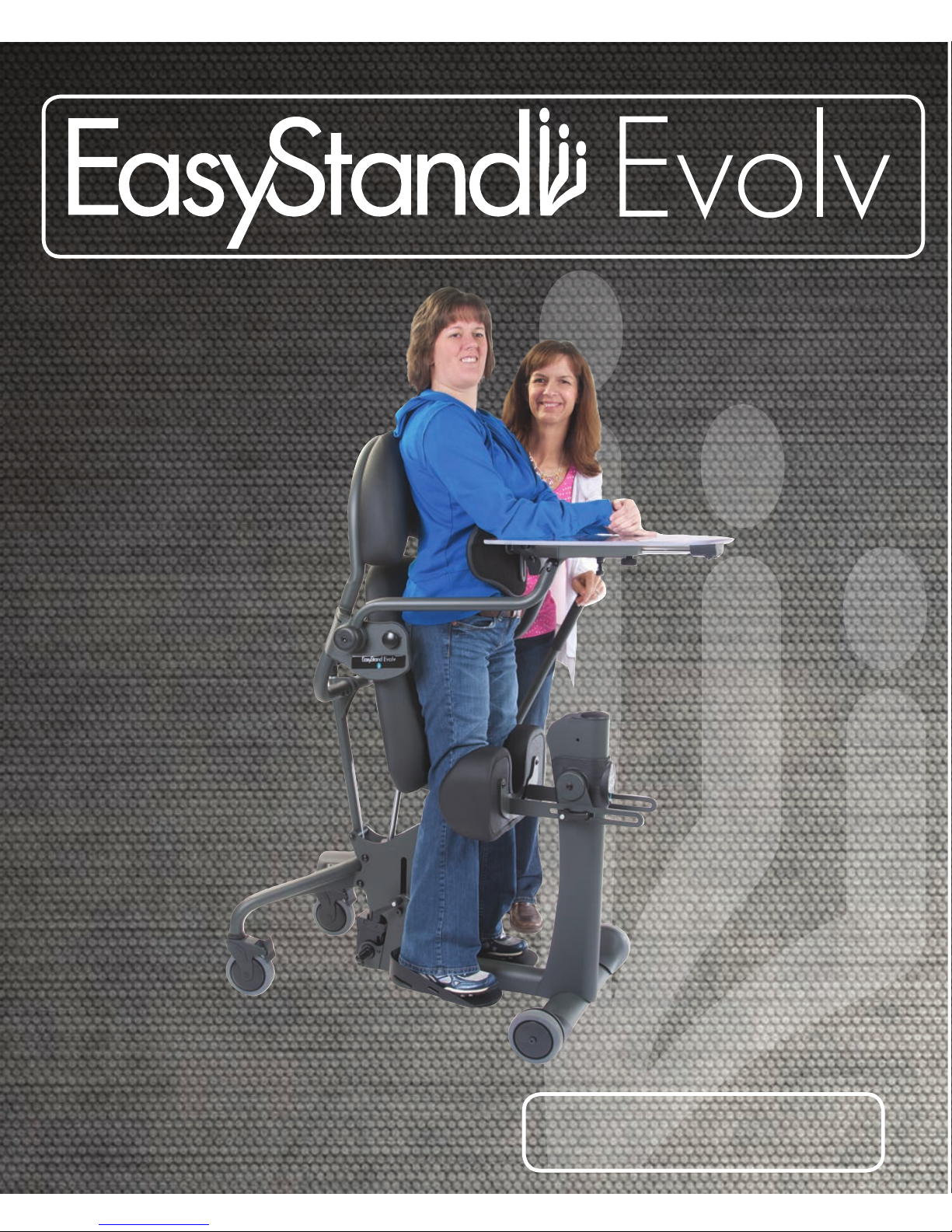
EasyStand Evolv User manual

Owner’s Manual
®

800.342.8968 www.easystand.com
SYMBOL LEGEND
!CAUTION/ATTENTION
PINCHPOINT
SERIAL NUMBER
SN
ENVIRONMENTAL
CONDITIONS
DATE OF MANUFACTURE
Please be environmentally responsible and recycle this product through your recycling facility at its end of
life.
Afin de préserver l’environnement, veuillez confier ce produit à votre centre de recyclage à la fin de sa
durée de vie.
Nachdem dieses Produkt ausgedient hat, entsorgen Sie es bitte auf umweltfreundliche Weise, indem Sie es zu der
entsprechenden Recyclingstelle bringen.
Wees a.u.b. milieubewust en recycleer dit product via uw recycleerder na het verstrijken van de levensduur.
Sea responsable con respecto al medio ambiente y recicle este producto al finalizar su vida útil en el lugar de reciclaje
correspondiente.
Siate responsabili verso l’ambiente e riciclate questo prodotto, al termine della sua vita d’uso, presso la vostra sede di
riciclaggio.
Kierrätä tämä tuote sen käyttöiän lopussa ympäristövastuullisella tavalla paikallisella kierrätyslaitoksella.
Var miljömedveten och återvinn denna produkt efter dess användning.
Vi ber deg ta hensyn til miljøet og resyklere dette produktet ved hjelp av de rette resykleringsfasilitetene når produktet
ikke lenger kan brukes.
Vis venligst hensyn til miljøet ved at levere produktet til det nærmeste genbrugsanlæg, når det ikke længere fungerer.
Por favor, assuma responsabilidade ambiental, reciclando este produto em suas instalações de reciclagem no final de
sua vida útil.
SEE INSTRUCTIONS FOR USE
TYPE BF APPLIED PART

Introduction .............................1
Safety Precautions ........................ 2
EasyStand Evolv Assembly.................. 3
Swing-Away Front ..................... 7
Shadow Tray ......................... 9
Mobile ............................. 11
Pow’r Up Lift Option .................. 13
Option Assembly ..................... 18
Adjusting the Evolv.......................27
Shadow Tray Adjustments .................30
Evolv Options & Parts Detail ............... 31
Perfect Fit Guide ........................ 35
Transferring ............................ 36
Standing............................... 37
Maintenance ............................38
Troubleshooting .........................39
Limited Warranty ....................... .40
page 39
Videos on assembly & fitting can be viewed at www.easystand.com/videos
Date Purchased Serial #
Note: The serial number is located
under the seat in the seat column.
Table of Contents

Introduction
page 1 page 38
Introduction
Congratulations on the purchase of an EasyStand standing frame! We at Altimate Medical have designed the
EasyStand with comfort and happiness in mind.
EasyStand Description
The EasyStand line of products is intended for individuals who are able to transfer independently or with
assistance from a caregiver and/or lifting device. It is a useful tool for rehabilitation, home, school, and work
use. EasyStand standing frames support the user from sitting to the standing position. Various options such
as support, choice of manual or Pow’r Up Lift may be added to facilitate individual needs.
Indications for Use
The EasyStand Evolv line of products is intended to assist individuals who have difficulty rising from a seat-
ed position to a standing position and is indicated for individuals weighing up to 200 lbs. (Medium), 280 lbs.
(Large), and 350 lbs. (XT).
This manual is an integral part of the standing system and should be read completely and thoroughly
by anyone operating the unit. This will ensure the EasyStand is assembled properly and used in the most
beneficial manner.
Altimate Medical recommends that an attendant be present when the EasyStand is being used. Should
any problem arise that cannot be solved by reading this manual, please contact a local supplier or call
Altimate Medical, Inc., at 800-342-8968 or 507-697-6393.
It is necessary to inspect the EasyStand Evolv at least weekly to ensure it is in safe operating condition.
EasyStand adjustments that are listed in the product owner’s manual can be made by the operator by
following the instructions for use. After an adjustment is made, inspect the EasyStand to ensure all
hardware and adjustable components are properly secured per the instructions for use. Replacement of
worn parts, major adjustments, or any other important corrections should be handled by an authorized
supplier or service center. Only Altimate Medical, Inc., approved replacement parts should be used to
ensure safety and performance.
Do not use the EasyStand without consulting a physician. Failure to consult a qualified
physician prior to using the EasyStand could lead to severe medical problems. We recommend
a good standing program be established and supervised by a qualified physician or physical
therapist.
Join the Standing Community!
Our goal is simple - to empower people with disabilities to stand up for their health. Connect, share, and
learn from other people with disabilities, special needs parents, clinical professionals, and the experts in
standing on one of our social networks. By keeping your standing program “top of mind” you will have the
greatest chance of maintaining a standing routine that maximizes all the benefits of standing!
Read, share, and comment on the EasyStand Blog at blog.easystand.com
Find EasyStand on these social networking sites:

page 37 page 2
Safety Precautions
Safety Precautions
• If a user does not meet these specifications and has not been properly fitted by a qualified therapist or physician, Altimate
Medical, Inc., does not recommend using the EasyStand.
Evolv Medium - is designed to accommodate most individuals from 4’0”-5’6” (122-168 cm) and up to 200 lbs. (90 kg)
Evolv Large - is designed to accommodate most individuals from 5’0”-6’2” (152-188 cm) and up to 280 lbs. (127 kg)
Evolv XT - is designed to accommodate most individuals from 6’0”-6’10” (183-209 cm) and up to 350 lbs. (159 kg)
For more detailed specifications visit our website www.easystand.com
• Altimate Medical, Inc., recommends consulting with a therapist or physician prior to starting a standing program.
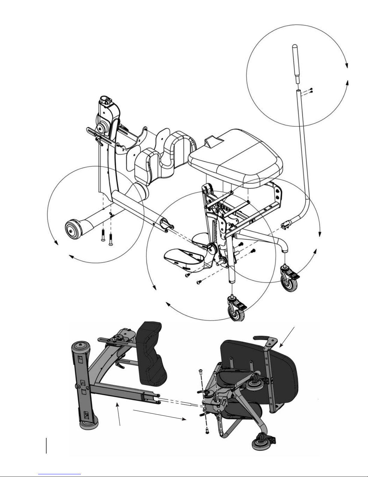
• Check the EasyStand periodically ensure that all nuts, bolts and adjustable parts are tightened securely.
• Never make adjustments to the EasyStand while a user is in the standing position.
• Never reposition the foot plates while a user is in the standing position. Consult with a therapist or physician for proper foot
placement and angle.
• It is necessary to inspect the EasyStand Evolv at least weekly to ensure it is in safe operating condition. Pay particular attention for
loose hardware. If the EasyStand is equipped with the optional Pow’r up lift please inspect the electrical cables for any wear and to
ensure they are attached properly. Replacement of worn parts, major adjustments, or any other important corrections should be
handled by an authorized dealer or service center. Only Altimate Medical, Inc., approved replacement parts should be used to ensure
safety and performance.
• If the EasyStand is being used in the home environment, please inspect the unit prior to each use to ensure there is no damage or
unexpected wear to the EasyStand that may have been caused unintentionally by pets, pests or children.
• If the unit was exposed to temperatures of less than 50˚F (10˚C), the unit must warm to room temperature before use.
• Operating Conditions: Temperature: 41˚F (5˚C) -104˚F (40˚C), Relative humidity: 20% - 90% at 86˚F (30˚C), Atmospheric
Pressure: 700 to 1060hPa.
• Storage/Transport Conditions: Temperature: 14˚F (-10˚C) -122˚F (50˚C), Relative humidity: 20% - 90% at 86˚F (30˚C),
Atmospheric Pressure: 700 to 1060hPa.
• The EasyStand can be used at a maximum altitude of 3,050 meters (10,000 feet).
• The expected service life of an EasyStand is considered 5 years under normal use conditions. Note: This may vary based upon use.
• Use body weight to lower the seat. Do not use excessive force.
• The EasyStand is for indoor use on level surfaces only.
• Violently thrusting in the EasyStand may cause it to tip.
• Always put the rear casters and/or wheels in the locked position before transferring into the EasyStand. Use these locks to keep the
EasyStand stationary.
• The EasyStand Evolv meets EN12182:1999 (test standard) for strength, durability and tipping stability.
• Please contact Altimate Medical, Inc., for relevant clinical data and literature, strength, durability and test results as applicable.
• The EasyStand Evolv Electric Lift meets the requirements of IEC 60601-1 and 60601-2.*
• Altimate Medical products are specifically designed to be used with Altimate Medical accessories and options. Unless otherwise
noted, accessories and options from other manufacturers have not been tested by Altimate Medical and are not recommended for
use with Altimate Medical products.
• Product Modifications made without express written consent (including, but not limited to, modification through the use of
unauthorized parts or attachments) are not recommended and will void the product warranty.
• The wheel lock on the mobile option is to keep the unit in place while transferring or standing stationary and it is not intended to be
used as a dynamic brake to stop a rolling mobile unit.
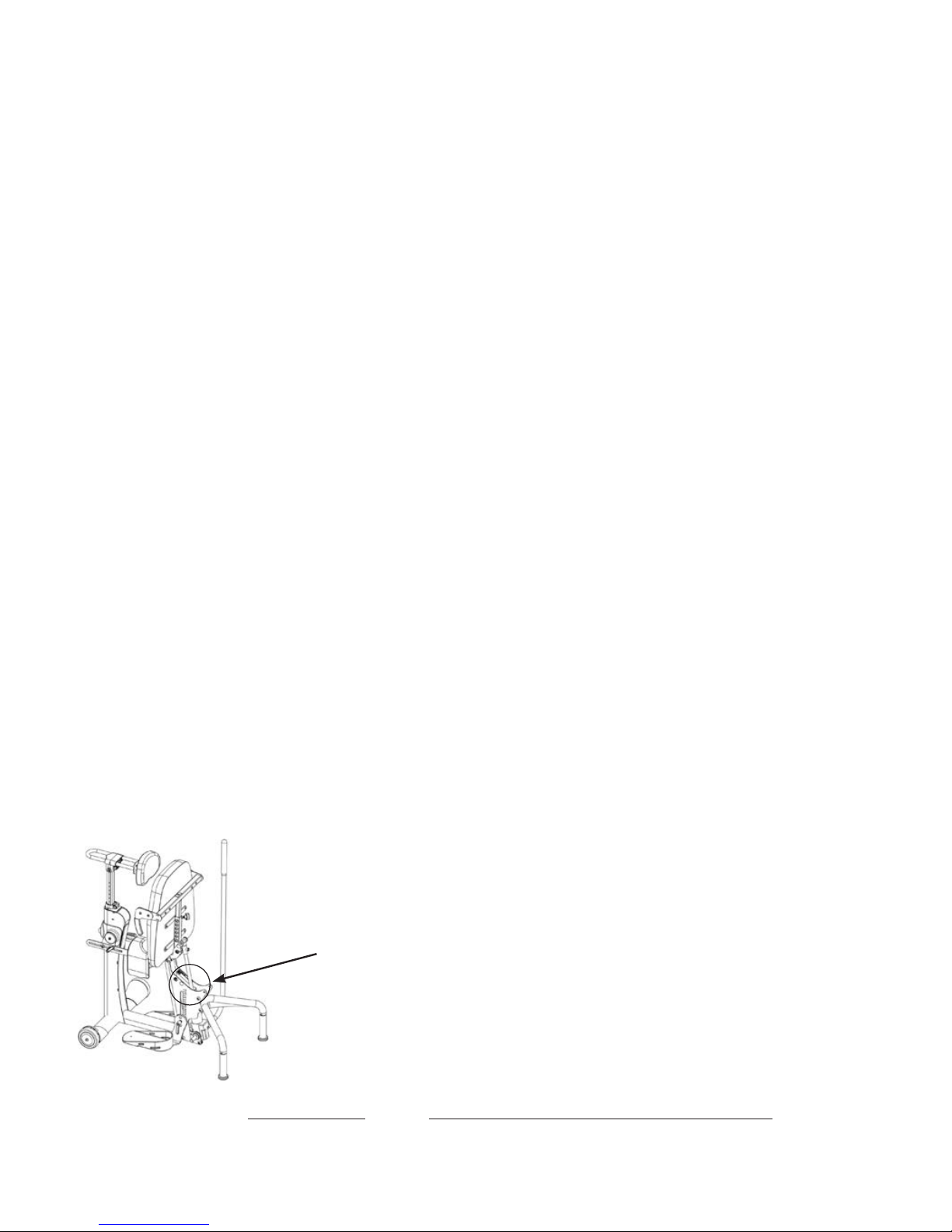
Caution: This equipment is designed to accommodate a range of users; therefore the unit has various adjustment slots and holes.
Avoid placing fingers or other body parts in any of these areas.
Caution: While in use this equipment has various moving parts, familiarize yourself with the unit and avoid placing hands or fingers
near any of these areas.
Caution: Advise bystanders to keep clear of the unit while in use.
Caution: Do not use the EasyStand Evolv Mobile option on an incline, it is intended for level surfaces only. Doing so may cause the
unit to tip.
* Evolv Pow’r Up Lift Option Only
!
!
!
!

EasyStand Evolv Assembly
®®
page 3 page 36
Videos of EasyStand Evolv assembly & fitting can be viewed at
www.easystand.com/videos
FIG. 3B
FIG. 2
FIG. 1
FIG. 3A
FIG. 2B
Front Frame
Seat Assembly
EasyStand Evolv Assembly

EasyStand Evolv Assembly
FIG. 2A
FIG. 3A
page 35 page 4
For Mobile assembly refer to p. 11
If the Evolv XT was ordered, the unit will be fully assembled
except for the tray and back option. Refer to p. 18 for the
back option assembly, p. 23 for the tray assembly and p. 9 for
the Shadow Tray. For any other option assembly, please refer
to pp. 18-26.
FIG. 1- Attach the front caster frame to the front frame with
bolts and tighten securely.
FIG. 2A- Attach the casters to the rear base frame. Tighten
securely using the provided wrench. Ensure the casters are
flush with the rear base frame. The casters are supplied with
a locking compound pre-applied to the threaded stem. Do not
remove this material, it is important to prevent the casters
from loosening over time.
FIG. 2B- Place the front frame and the seat assembly on it’s
side, slide the front frame into the opening of the seat
assembly as shown. Line up holes and insert all four bolts
first, then place nuts onto bolts and tighten securely with hex
wrench and 19mm open-ended wrench. Place unit upright on
its wheels.
If the Swing-Away Front option was ordered, slide the front
frame into the opening of the seat assembly as shown on p.
7. To help with installation, place folded cardboard or a block
of wood underneath the frame for support. Start all four bolts
first, then tighten securely.
For more Swing-Away Front assembly, refer to p. 7.
Lift seat up and flip foot plates down. Then insert ratchet
handles (located in bag with owner’s manual, E3 model
will have ratchet handle already attached) into foot plates.
Tighten securely.
FIG. 3A- Attach the pump handle to the pump on the seat
assembly with bolts and nuts, tighten securely.
FIG. 3B- Insert top of handle into pump handle and tighten
bolts securely.

page 5
EasyStand Evolv Assembly
FIG. 6
FIG. 4
FIG. 5

page 33 page 6
EasyStand Evolv Assembly
FIG. 5
FIG. 4
Evolv E3
Spacer
If the Swing-Away Front was ordered, please refer to pp. 7-8.
If the Independent Kneepads were ordered refer to p. 25.
FIG. 4- Remove ratchet handle and hardware from the knee
bracket. Place the bracket and hardware onto the column in
the order shown. Ensure the spacer is placed between the
two steel brackets. Place the washer and bracket bolt into
the bracket assembly and tighten snug, ensuring the knee
bracket moves freely. Do NOT overtighten bolt. Place the
washer and ratchet handle into the bracket assembly. Tighten
ratchet handle once desired position is reached.
Remove the three bolts from the kneepad making sure the
plastic insert stays in place. Place the kneepad onto the
bracket and insert top two bolts before inserting the middle
bolt. Tighten securely. If the independent kneepads were
ordered, place pads into knee bracket, make sure the larger
end of the pad is on the outside of the unit (see drawing on
p. 25).
If the Shadow Tray was ordered, please refer to pp. 9-10.
FIG. 5- Insert the tray post into the front column with the
holes in the post facing upward. The tray clamp on the front
frame may need to be adjusted to fit the tray post into the
frame. Place tray onto the tray post, insert nut into slot and
bolt into hole, tighten securely.
If any additional options were ordered, please refer to the
drawings on pp. 18-26.
FIG. 6- Install the seat onto the seat assembly after all other
options are added. For easier installation, pump the seat half-
way up. Start all four bolts first, then tighten
securely.
For Evolv adjustments, see pp. 27-30.
Evolv Options & Parts Detail (rear)

page 7
Swing-Away Front Assembly
FIG. 7
FIG. 9
FIG. 8
Tray Frame
H-Frame
Front Caster Frame
Tray
Kneepad
Bracket
FIG. 8
FIG. 7
Swing-Away Front
for Shadow Tray
Crossbar

page 31 page 8
Swing-Away Front Assembly
FIG. 7- Insert the H-frame into the front caster frame. Insert
pins into the holes provided (crossbar should face seat).
If the Front Swivel Casters were ordered refer to p. 24.
If the Independent Kneepads were ordered refer to p. 25.
FIG. 8- Place the kneepad bracket onto the H-frame. Remove
the three bolts from the kneepad making sure the plastic
insert stays in place. Place the kneepad onto the bracket
and insert the top two bolts before inserting the middle bolt.
Tighten securely.
If the Shadow Tray was ordered, skip to p. 9.
FIG. 9- Insert the tray frame into the H-frame, tighten knobs
securely. Place the tray onto the tray frame, install knobs.
Tighten nuts securely.
Note: Tray will not move if nuts are overtightened.
To use the Swing-Away Front:
To swing away the front for transferring, remove pull pins
from the bottom of the H-frame. Lift collar and swing away.
After positioning client in stander, swing front back into
front caster frame and replace pins, making sure the collar is
secure.
Caution: Collar and pins must be securely in place before the
user transitions into the standing position.
For Evolv adjustments, see p. 27.
FIG. 8
FIG. 9
!

page 9
Shadow Tray Assembly
Shadow Tray Bracket Set-up
®
FIG. 10- On the support arm, remove the plastic
bag with two mounting bolts and a silver pin.
Using a hex wrench, remove the end cap from
the Shadow Tray arm.
End Cap
FIG. 11- Release the plunger by pulling it down,
twist to keep it released.
FIG. 12- Insert the silver pin into the support arm as
shown, while supporting the silver pin, place the support
arm into the Shadow Tray bracket until it clicks into place.
Silver Pin
Shadow Tray Bracket
Support Arm
FIG. 13- The knobs on the end of the support arm should
be exposed. Rotate the arm down to 90˚. Lock the plunger
into place.
Knobs
FIG. 14- Use a rubber mallet to tap the black cap into the
Shadow Tray bracket. Replace the end cap and tighten
securely.
These assembly instructions are
shown for the right side mounted
Shadow Tray, for the left side
mounted Shadow Tray, installation
will be on the opposite side.

FIG. 16
page 29 page 10
Shadow Tray Assembly
FIG. 15
FIG. 15- To install the support arm, first remove the nut from
the pre-assembled bolt on the arm, leaving the bolt and the
two halves of the fitting (one plastic and one metal) in place
on the tube. Thread the bolt into the hip plate, as shown in
Fig. 16. Once the bolt has been secured and the support arm
has the desired level of tension, install the nut and lock
washer on the bolt protruding through the opposite side of
the hip plate, closest to the user. Use either the small end
of the wrench from the supplied tool kit, or a 17mm socket
wrench (preferred) to securely tighten the nut, see p. 30. A
setscrew in the metal half of the support arm fitting may be
used to adjust the level of the tray once the installation is
complete.
FIG. 16- Install the tray arm rest to the unit with the two
bolts attached. Tighten bolts securely.
FIG. 17- Place chest pad onto tray tubes. Place tray onto
bracket and insert the bolts into the bracket and tighten
securely.
For Shadow Tray adjustments, see p. 30.
FIG. 16
FIG. 17

page 11 page 28
Mobile Assembly
Mobile Assembly
FIG. 18
FIG. 20
Mobile
Assembly
Mobile
Bracket
Mobile
Bracket
Knee pad
Bracket
FIG. 19
Wheel Frame
FIG. 21
FIG. 22

page 27 page 12
Mobile Assembly
FIG. 18- Place the front frame onto the wheel frame. Line up
the two bolts with the holes on the wheel frame, start both
bolts before tightening securely.
FIG. 19- Attach the casters to the rear base frame. Tighten
securely using the provided wrench. Ensure the casters are
flush with the rear base frame. The casters are supplied with
a locking compound pre-applied to the threaded stem. Do not
remove this material, it is important to prevent the casters
from loosening over time.
FIG. 20- Place the front frame and the seat assembly on its
side, slide the front frame into the opening of the seat
assembly as shown. Line up holes and insert all four bolts
first, then place nuts onto bolts and tighten securely with hex
wrench and 19mm open-ended wrench. Place unit upright.
FIG. 21- Place the left-side mobile assembly onto the wheel
frame. Line up holes and insert top bolt through the inside as
shown. Place the nut onto the bolt and hand tighten. Line up
holes and insert bottom bolt through the outside, as shown.
Hand tighten the nut onto the bolt, then tighten both bolts
securely with a 19mm wrench and hex wrench. Repeat on
the opposite side before continuing to the next step.
FIG. 22- Place mobile bracket onto the kneepad bracket.
Place kneepad onto the mobile bracket. Insert three bolts
into the back of the kneepad. Tighten bolts securely. Remove
bolts from mobile bracket. Flip down kneepad and align
bracket on mobile assembly. Tighten bolts and nuts securely
with 13mm wrench and hex wrench. Repeat steps on the
opposite side before continuing to the next step.
Lift seat up and flip foot plates down. Then insert ratchet
handles into foot plates. Tighten securely.
FIG. 23- The Mobile is equipped with wheel locks for safety
while transferring and stability while performing stationary
activities. Note the directional arrows imprinted in the center
hub of each handrim.
To assemble the tray and seat, go to pp. 6, FIG. 5.
Wheel
Locks
Front Frame
Wheel Frame
FIG. 18
FIG. 21
FIG. 22
FIG. 23

page 13 page 26
Pow’r Up Lift Option
Charging the Battery
The EasyStand Evolv Pow’r Up Lift uses two 12 volt sealed lead batteries rated at 2.9 amps each.
An EasyStand Evolv can be lifted approximately 100 times on one full battery charge. An audible
alarm will sound when the battery is low. Please charge the battery after the alarm sounds. A bat-
tery needing to be fully recharged will take approximately 8 hours.
The EasyStand Evolv can be raised to the standing position while
being charged. The function of the charger is to detect a full bat-
tery and then provide a constant potential power supply to hold the
battery at a full condition without overcharging. When the battery
EMF rises to a factory preset point, the charger circuit will not allow
the peak output voltage to exceed that value. This factory setting
protects a battery from excessive depletion of electrolyte, which
can occur from overcharging. The charger can be found in the tool
pouch on the back of the unit.
CAUTION: Use only the Linak charger, model numbers 00CH01-XX
OR 10CH01S-00, provided by Altimate Medical with the Pow’r Up
option.
1. Plug the receptacle into a wall outlet. The light on the charger will
be green indicating an open circuit.
2. FIG. A- Plug the charger cord into the side of the hand control.
The light on the charger will turn yellow indicating the batteries are
being charged.
3. FIG. B- The unit will arrive unplugged from the battery, plug in the
white cord that supplies power to the actuator and the black cord
that supplies power to the remote. The black cord has a notch on it
to orient the connector properly. Fully charge battery before use.
Note: The white cord has a rubber washer on it, which makes it very
sticky and sometimes will not get pushed in completely, make sure
to push the cord all the way into the battery.
4. When the batteries are charged, the light on the charger will turn
green.
5. Fully charge the batteries every three months or less during periods of intermittent or non-use.
CAUTION: Ensure the cables are attached properly per the instructions for use. Do not allow the
cables to drag on the floor or to catch on objects.
FIG. A
FIG. B
!
!
Pow’r Up Lift
The hand pendant
is a Type BF applied
part.

page 25 page 14
Pow’r Up Lift Option
Standard Unit
Mobile Unit
!
Assembly of the Hand Control
FIG. C1- If the Mobile Option was ordered, assemble the hand
control as illustrated in Fig. C1.
FIG. C2- If no Mobile Option was ordered, assemble the hand
control as illustrated in Fig. C2.
CAUTION: The Evolv Pow’r Up Option is not designed for
continuous use. Duty Cycle 5% Max, 1 min. / 19 min.
Raising the Lift - Press the UP (arrow up) button on the hand
control to lift the seat.
Lowering the Lift - Press the DOWN (arrow down) button on
the hand control to lower the seat.
Battery Replacement
The batteries are enclosed in the control box of the Pow’r Up
Lift (the black box where the cords are plugged in). Once the
batteries have reached the end of their life and need to be
replaced, do not open the control box; please contact Altimate
Medical customer service or a medical equipment dealer for
information about purchasing a replacement control box. It is
recommended that the batteries be replaced every four years.
Please contact a local recycling authority for information about
disposing old batteries.
IP Rating
The IP rating is a classification system indicating the protection
degree from dust, water and impact for electrical equipment
and enclosures. Pow’r Up Lift components are rated at IP21. The
definition for IP21 is as follows:
First character definition: 2 - Protected against solid foreign
objects of 12.5mm diameter and greater.
Second character definition: 1 - Protected against vertically
falling water drops.
Electromagnetic compatibility
Pow’r Up Option components have been designed and tested
to meet the applicable EMC requirements. Problems with the
EasyStand due to inadequate electromagnetic compatibility is
unlikely, however, if any unusual (such as intermittent)
behavior of the Pow’r Up option and the EasyStand is noticed
and it is being used next to possible interfering equipment such
as mobile phones, microwaves, or radio broadcast masts, this
could be an indication of electromagnetic interference. If such
behavior occurs, use the mechanical release to lower the unit
to the seated position and move the EasyStand away from the
interfering equipment. Please report any instance of
possible electromagnetic interference to AMI’s Customer
Service Department.
FIG. C2
FIG. C1

page 15 page 24
Pow’r Up Lift Option
Guidance and Manufacturer’s Declaration - Electromagnetic Emissions
The EasyStand Evolv is intended for use in the electromagnetic environment specified below. The customer or the user
of the EasyStand Evolv should assure that it is used in such an environment.
Emissions Test
RF emissions CISPR 11 Group 1 The EasyStand Evolv uses RF energy only for its
internal function. Therefore, its RF emissions are
very low and are not likely to cause any interference
in nearby electronic equipment.
The EasyStand Evolv is suitable for use in all estab-
lishments, including domestic establishments and
those directly connected to the public low-voltage
power supply network that supplies buildings used
for domestic purposes.
Compliance Electromagnetic Environment - Guidance
RF emissions CISPR 11 Class B
Harmonic emissions
IEC 61000-3-2
Class A
Voltage fluctuations/
Flicker emissions
IEC 61000-3-3
Complies
Guidance and Manufacturer’s Declaration - Electromagnetic Immunity
The EasyStand Evolv is intended for use in the electromagnetic environment specified below. The customer or the user
of the EasyStand Evolv should assure that it is used in such an environment.
Immunity Test
Electrostatic
Discharge (ESD)
IEC 61000-4-2
± 6 kV contact
± 8 kV air
± 6 kV contact
± 8 kV air
Floors should be wood, concrete, or ceramic tile. If
floors are covered with synthetic material, the rela-
tive humidity should be at least 30 %.
Mains power quality should be that of a typical com-
mercial or hospital environment.
IEC 60601
Test Level
Electromagnetic Environment - Guidance
Electrical Fast
Transient/Burst
IEC 61000-4-4
± 2 kV for power
supply lines
± 1 kV for input/
output
lines
Surge
IEC 61000-4-5
± 1 kV line(s) to
line(s)
± 2 kV line(s) to
earth
Compliance
Level
± 2 kV for power
supply lines
± 1 kV for input/
output
lines
± 1 kV line(s) to
line(s)
± 2 kV line(s) to
earth
Mains power quality should be that of a
typical commercial or hospital environment.
Voltage dips, short
interruptions and
voltage variations on
power supply input
lines
IEC 61000-4-11
<5 % UT
(>95 % dip in UT)
for 0,5 cycle
40 % UT
(60 % dip in UT)
for 5 cycles
70 % UT
(30 % dip in UT)
for 25 cycles
<5 % UT
(>95 % dip in UT)
for 5 s
<5 % UT
(>95 % dip in UT)
for 0,5 cycle
40 % UT
(60 % dip in UT)
for 5 cycles
70 % UT
(30 % dip in UT)
for 25 cycles
<5 % UT
(>95 % dip in UT)
for 5 s
Mains power quality should be that of a typical
commercial or hospital environment. If the user of
the EasyStand Evolv requires continued operation
during power mains interruptions, it is recommended
that the EasyStand Evolv be powered from an
uninterruptible power supply or a battery.
Power frequency
(50/60 Hz) magnetic
field
IEC 61000-4-8
3 A/m 3 A/m Power frequency magnetic fields should be at levels
characteristic of a typical location in a typical
commercial or hospital environment.
NOTE: UTis the a.c. mains voltage prior to application of the test level.

Portable and mobile RF communications equipment
should be used no closer to any part of the EasyStand
Evolv, including cables, than the recommended
separation distance calculated from the equation
applicable to the frequency of the transmitter.
Recommended separation distance
d= 1.2 √
d= 1.2 √80 MHz to 800 MHz
d= 2.3 √800 MHz to 2.5 GHz
Where Pis the maximum output power rating of the
transmitter in watts (W) according to the transmitter
manufacturer and dis the recommended separation
distance in meters (m).
Field strengths from fixed RF transmitters, as deter-
mined by an electromagnetic site surveya, should
be less than the compliance level in each frequency
range.b
Interference may occur in the vicinity of equipment
marked with the following symbol:
page 23 page 16
Pow’r Up Lift Option
Guidance and Manufacturer’s Declaration - Electromagnetic Immunity
The EasyStand Evolv is intended for use in the electromagnetic environment specified below. The customer or the user
of the EasyStand Evolv should assure that it is used in such an environment.
Immunity Test
Conducted RF
IEC 61000-4-6
3 Vrms
150 kHz to 80
MHz
3 Vrms
IEC 60601
Test Level
Electromagnetic Environment - Guidance
NOTE 1: At 80 MHz and 800 MHz, the higher frequency range applies.
NOTE 2: These guidelines may not apply in all situations. Electromagnetic propagation is affected by absorption and
reflection from structures, objects, and people.
Compliance
Level
Radiated RF
IEC 61000-4-3
3 V/m
80 MHz to 2.5
GHz
3 V/m
aField strengths from fixed transmitters, such as base stations for radio (cellular/cordless) telephones and land mobile
radios, amateur radio, AM and FM radio broadcast and TV broadcast cannot be predicted theoretically with accuracy.
To assess the electromagnetic environment due to fixed RF transmitters, an electromagnetic site survey should be
considered. If the measured field strength in the location in which the EasyStand Evolv is used exceeds the
applicable RF compliance level above, the EasyStand Evolv should be observed to verify normal operation. If abnormal
performance is observed, additional measures may be necessary, such as re-orienting or relocating the
EasyStand Evolv.
bOver the frequency range 150 kHz to 80 MHz, field strengths should be less than 3 V/m.
P
P
P

page 17 page 22
Pow’r Up Lift Option
Recommended separation distances between
portable and mobile RF communications equipment and the EasyStand Evolv
The EasyStand Evolv is intended for use in an electromagnetic environment in which radiated RF disturbances are
controlled. The customer or the user of the EasyStand Evolv can help prevent electromagnetic interference by
maintaining a minimum distance between portable and mobile RF communications equipment (transmitters) and the
EasyStand Evolv as recommended below, according to the maximum output power of the communications
equipment.
Rated maximum output
power of transmitter
150 kHz to 80 MHz 80 MHz to 800 MHz 800 MHz to 2.5 GHz
Separation distance according to frequency of transmitter
d= 1.2 √P
m
d= 1.2 √Pd= 2.3 √P
.12 .12 .23
.38 .38 .73
1.2 1.2 2.3
3.8 3.8 7.3
12 12 23
W
0.01
0.1
1
10
100
NOTE 1: At 80 MHz and 800 MHz, the higher frequency range applies.
NOTE 2: These guidelines may not apply in all situations. Electromagnetic propagation is affected by absorption and
reflection from structures, objects, and people.
For transmitters rated at a maximum output power not listed above, the recommended separation distance din meters
(m) can be estimated using the equation applicable to the frequency of the transmitter, where Pis the maximum output
power rating of the transmitter in watts (W) according to the transmitter manufacturer.
FIG. E
!
Activating the Mechanical Emergency Release
All Altimate Medical electric lift products are equipped with a
mechanical release to be used in emergency situations.
CAUTION: Using the emergency mechanical release as the
primary means to return to the seated position can cause
damage to the unit. Only use the mechanical release in emer-
gency situations.
FIG. E- The release allows the user to be lowered to a seat-
ed position in the unlikely occurrence of the battery losing
charge while the user is in a standing position. The actuator
only retracts if the release is pulled and there is weight on
the seat. The release is located on the left side of the seat
and is signified by a red tag with the word “EMERGENCY”.
1. To activate the emergency mechanical release pull out the
quick release pin located on the left side of the seat.
2. Squeeze the handle and if necessary, push down on the
seat.
Other manuals for Evolv
2
Table of contents
Popular Blood Glucose Meter manuals by other brands

Pogo
Pogo Automatic quick start guide

All Medicus
All Medicus GlucoDr SuperSensor user manual

Lifescan
Lifescan ONE TOUCH BASIC BLOOD GLUCOSE MONITORING... owner's booklet

EPS Bio Technology
EPS Bio Technology Easy Pain Supreme user manual

Abbott
Abbott AlphaTRAK 2 Quick user guide

OSANG Healthcare
OSANG Healthcare GluNEO M3 user manual