manuals.online logo
Brands
  1. Home
  2. •
  3. Brands
  4. •
  5. Eaton
  6. •
  7. Rack & Stand
  8. •
  9. Eaton RE 2 User manual

Eaton RE 2 User manual

Other Eaton Rack & Stand manuals

Eaton Powerware Series User manual

Eaton

Eaton Powerware Series User manual

Eaton 9E1000IR Assembly instructions

Eaton

Eaton 9E1000IR Assembly instructions

Eaton xStorage Home Quick start guide

Eaton

Eaton xStorage Home Quick start guide

Eaton PDI Universal User manual

Eaton

Eaton PDI Universal User manual

Eaton TRIPP LITE Series User manual

Eaton

Eaton TRIPP LITE Series User manual

Eaton AMT Vari-Depth Manual

Eaton

Eaton AMT Vari-Depth Manual

Eaton KA146W5 Instruction manual

Eaton

Eaton KA146W5 Instruction manual

Eaton ALL-PRO WPFLD-TRN User manual

Eaton

Eaton ALL-PRO WPFLD-TRN User manual

Eaton Two Post Rack User manual

Eaton

Eaton Two Post Rack User manual

Eaton Paramount Enclosure User manual

Eaton

Eaton Paramount Enclosure User manual

Eaton Series NRX Manual

Eaton

Eaton Series NRX Manual

Popular Rack & Stand manuals by other brands

Dynex DX-MP3MT Quick setup guide

Dynex

Dynex DX-MP3MT Quick setup guide

Konig & Meyer 24185 manual

Konig & Meyer

Konig & Meyer 24185 manual

ECG LD 326501 instruction manual

ECG

ECG LD 326501 instruction manual

Philips SB7S19S/00 quick start guide

Philips

Philips SB7S19S/00 quick start guide

Woodline KIT-250 lb instructions

Woodline

Woodline KIT-250 lb instructions

ricoo S1222 installation instructions

ricoo

ricoo S1222 installation instructions

Kanto P301 user manual

Kanto

Kanto P301 user manual

VidaBox VB MNT FFS2 installation guide

VidaBox

VidaBox VB MNT FFS2 installation guide

PROEL PLWIN60C user manual

PROEL

PROEL PLWIN60C user manual

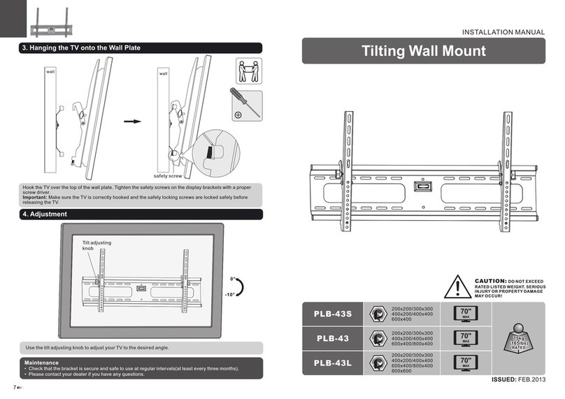
AllMounts PLB-43S instruction manual

AllMounts

AllMounts PLB-43S instruction manual

VMP VH-001 instruction sheet

VMP

VMP VH-001 instruction sheet

Nederman SYSTEM 920/400 instruction manual

Nederman

Nederman SYSTEM 920/400 instruction manual

Glasdon ORBIS POST MOUNTING KIT installation guide

Glasdon

Glasdon ORBIS POST MOUNTING KIT installation guide

Songmics LGR105 manual

Songmics

Songmics LGR105 manual

Grape GM401 user manual

Grape

Grape GM401 user manual

FourStarGroup 11225296 manual

FourStarGroup

FourStarGroup 11225296 manual

CHIEF FLR100 installation instructions

CHIEF

CHIEF FLR100 installation instructions

FEC XDCAM EX PMW-EX30 manual

FEC

FEC XDCAM EX PMW-EX30 manual

manuals.online logo
manuals.online logoBrands
  • About & Mission
  • Contact us
  • Privacy Policy
  • Terms and Conditions

Copyright 2025 Manuals.Online. All Rights Reserved.

1
Installation Guide
RE 2 Post Rack Assembly and Installaon Guide Issue 1
RE 2 Post Rack System
2
Installation Guide
RE 2 Post Rack Assembly and Installaon Guide Issue 1
TABLE OF CONTENTS
SAFETY WARNINGS 3
Frame Assembly Guide 4 - 6
Vertical Cable Manager Assembly Guide 7 + 8
Adjustable Cable Spools 9 + 10
Vertical Cable Basket 11
Earth Bonding 12
3
Installation Guide
RE 2 Post Rack Assembly and Installaon Guide Issue 1
1. SAFETY WARNINGS
This manual contains important instructions that you should follow during installation and main-
tenance of the RE 2 Post Rack system. Please read all instructions before operating the equip-
ment and save this manual for future reference.
1. WARNING! RE 2 Post Rack components can be very heavy. When lifting heavy
components or electronic equipment, ensure that all safety regulations are observed.
2. WARNING! The enclosure must be stabilized (bolted to floor) before installing any
accessory, component or electronic device. Failure to stabilize prior to installing equipment
may cause the enclosure to tip over.
3. WARNING! First, load the heaviest electronic devices and accessories into the bottom of
the rack to prevent the rack from becoming top-heavy and ensure the 19” equipment is
evenly loaded front to back in the RE 2 Post Rack (see diagram below);
4. WARNING! It is the customer’s responsibility to ensure that the floor has a structural load
capacity that will safety bear the weight of the RE 2 Post Rack and installed components.
5. WARNING! There must be an uninterruptable safety earth ground from the main power
source to the Power Distribution Unit’s PDU (if fitted) power cord set. Whenever it is likely
that ground has been impaired, disconnect the PDU’s power cord until the ground has been
restored.
6. WARNING! High leakage current may be present. Grounding connection essential before
connecting supply.
7. WARNING! Rack is intended to be used with equipment complying with IEC 60950. Use
with non-compliant equipment may result in electrical hazard.
8. WARNING! The installer is responsible for grounding the RE 2 Post Rack to the building
electrical system. Additional equipment can be electronically bonded to the rack's frame
using additional grounding points and appropriate fixings.


4
Installation Guide
RE 2 Post Rack Assembly and Installaon Guide Issue 1
ITEM DESCRIPTION QTY
1RE 2 POST VERTICAL MOUNTING RAIL 2
2RE 2 POST BOTTOM ANGLE 2
3RE 2 POST TOP ANGLE 2
4M8 SHAKEPROOF WASHER 8
5M8 x 20mm HEX HEAD BOLTS 8
6BRACKET ASSEMBLY FOR PDU & CABLE BASKET 2
5
1
2
4
3
1
2
3
4
5
2. RE 2 Post Rack Frame Assembly Guide
5
Installation Guide
RE 2 Post Rack Assembly and Installaon Guide Issue 1
 Step -1
Lay vertical mounting rails on a flat surface with
the open sides of the channel facing each other.
The rails should be approximately 450mm apart.
 Step - 2
Place the bottom angle on the vertical mounting
rails as shown in Figure 1.
Align the bottom angle holes with the holes in the
vertical mounting rails. Fasten using 4 x M8
washers and 4 x M8 x 20 Hex Head bolts, then
FINGER TIGHTEN.
 Step - 3
Place the top angle on the vertical
mounting rails as shown in Figure 2.
Align the top angle holes with the holes in
the vertical mounting rails. Fasten using 2
x M8 washers and 2 x M8 x 20 Hex Head
bolts, then FINGER TIGHTEN.
Figure -1
Item 1
Item 2
Item 4
Item 5
Figure - 2
Item 1
Item 3
Item 4
Item 5
 Step - 4
Turn the rack over and repeat Steps 2 and 3.
6
Installation Guide
RE 2 Post Rack Assembly and Installaon Guide Issue 1
 Step - 5
Stand the rack up and square as shown in Figure 3.
Tighten all fixings to 12 Nm (tolerance +/- 2 Nm)
 Step - 6
The bottom angles need to be secured to the floor
(floor fixings not included)
 Step - 7
If required, install the 2 Cable Basket / PDU brackets to
the RE 2 Post Rack vertical mounting rail side or, using
cage nuts, to the 19” rail.
Once secured to the floor the rack is now ready for
equipment installation.
SQUARE
Figure - 3
7
Installation Guide
RE 2 Post Rack Assembly and Installaon Guide Issue 1
3. RE 2 Post Rack Vertical Cable Manager Assembly
Guide
4
1
2
3
5
2
4
3
5
4
3
5
ITEM DESCRIPTION QTY
1RE 2 POST FRAME 1
2RE CABLE MANAGER 2
3M10 x 20 HEX HEAD BOLTS 6
4M10 WASHER 6
5M10 HEX FULLNUTS 8
8
Installation Guide
RE 2 Post Rack Assembly and Installaon Guide Issue 1
 Step -1
Ensure the RE 2 post frame is securely
fastened to the floor.
2 person assembly - Person one offers
the cable manager to the RE 2 Post
frame whilst Person two passes the Item
-3 through the frame (The fixing must pass through
the obround slot in the 2 Post frame) into the Cable
manager securing on the inside of the
manager with a Item-4+5 then FINGER
TIGHTEN. See figure-1
 Step - 2
Fix the Cable manager in 3 places -
Top, Middle & Bottom.
Figure -1
Item 2
Item 3
Item 4
Item 5
 Step - 3
Position the Cable Manager and Tighten all fixings
to 12 Nm (tolerance +/- 2 Nm)
 Step - 4
Repeat step 1-2 on the opposite side of the RE 2 Post rack
9
Installation Guide
RE 2 Post Rack Assembly and Installaon Guide Issue 1
4. RE 2 Post Rack Adjustable Cable Spools
ITEM DESCRIPTION QTY
1RE 2 POST RACK 1
2ADJUSTABLE CABLE SPOOL 5 PER KIT
3M5 THUMB NUTS 2 PER SPOOL
1
2
3
10
Installation Guide
RE 2 Post Rack Assembly and Installaon Guide Issue 1
 Step -1
Ensure the RE 2 Post
Rack frame is securely
fastened to the floor.
Remove the thumb
screws from spools
where fitted See figure-1
 Step - 2
Offer up a cable spool to the 2 holes in the
vertical rail (Note there are 5 positions
available on the rail). Thread on and
tighten the thumb nuts.
Figure -1
 Step - 3
Repeat step 1-2 where required.