ECCO STOVE 678EC User manual

678/03.05.23/V2
P a g e | 1of 28
Ecco Stove | Foster House | 2 Redditch Road | Studley | B80 7AX | United Kingdom
T| +44 (0) 1527 857 814 E| [email protected] W| www.eccostove.com
For all patents –See Addendum
ECCO STOVE MODEL 678EC and E850 Manual
SAVE THESE INSTRUCTIONS
TESTED TO EN15250 AND EN13240
CAUTION: HOT WHILE IN OPERATION. DO NOT TOUCH, KEEP CHILDREN, CLOTHING AND FURNITURE AWAY.
CONTACT MAY CAUSE SKIN BURNS –SEE NAME PLATE AND INSTRUCTIONS.
WARNING NOTE:
Properly installed, operated and maintained this stove will not emit fumes into the dwelling. Occasional fumes
from de-ashing and re-fuelling may occur. However, persistent fume emission is potentially dangerous and must
not be tolerated. If fume emission does persist, then the following immediate action should be taken:-
a) Open doors and windows to ventilate the room and then leave the premises.
b) Let the fire go out.
c) Check for flue or chimney blockage and clean if required.
d) Do not attempt to relight the fire until the cause of the fume emission has been identified and corrected.
If necessary seek expert advice.
The most common cause of fumes emission is flueway within the stove or chimney blockage. For your own safety
these must be kept clean at all times.
A CO detector must be fitted in the same room as this appliance to conform to UK requirements of installation.
The Clean Air Act 1993 and Smoke Control Areas
“Under the Clean Air Act local authorities may declare the whole or part of the district of the authority to be a
smoke control area. It is an offence to emit smoke from a chimney of a building, from a furnace or from any fixed
boiler if located in a designated smoke control area. It is also an offence to acquire an "unauthorised fuel" for use
within a smoke control area unless it is used in an "exempt" appliance ("exempted" from the controls which
generally apply in the smoke control area). The Secretary of State for Environment, Food and Rural Affairs has
powers under the Act to authorise smokeless fuels or exempt appliances for use in smoke control areas in England.
In Scotland and Wales this power rests with Ministers in the devolved administrations for those countries. Separate
legislation, the Clean Air (Northern Ireland) Order 1981, applies in Northern Ireland. Therefore it is a requirement
that fuels burnt or obtained for use in smoke control areas have been "authorised" in Regulations and that
appliances used to burn solid fuel in those areas (other than "authorised" fuels) have been exempted by an Order
made and signed by the Secretary of State or Minister in the devolved administrations. Further information on the
requirements of the Clean Air Act can be found here : http://smokecontrol.defra.gov.uk/Your local authority is
responsible for implementing the Clean Air Act 1993 including designation and supervision of smoke control areas
and you can contact them for details of Clean Air Act requirements “The Ecco Stoves 678EC2 has been
recommended as suitable for use in smoke control areas when burning wood logs with a maximum moisture
content of 20%”

678/03.05.23/V2
P a g e | 2of 28
Ecco Stove | Foster House | 2 Redditch Road | Studley | B80 7AX | United Kingdom
T| +44 (0) 1527 857 814 E| [email protected] W| www.eccostove.com
For all patents –See Addendum
ADDENDUM
Patents
United Kingdom: №: 2 213 945 (E)
№: 2 467 433
United States: №: 10 627 112
№: 9 523 505
Canada: №: 2 691 409
Germany: №: 60 2010 064 710.2
Belgium: №: 2 213 945 (E)
Switzerland: №: 2 213 945 (E)
Finland: №: 2 213 945 (E)
France: №: 2 213 945 (E)
Ireland: №: 2 213 945 (E)
Lithuania: №: 2 213 945 (E)
Netherlands: №: 2 213 945 (E)
Russia: №: 2 213 945 (E

678/03.05.23/V2
P a g e | 3of 28
Ecco Stove | Foster House | 2 Redditch Road | Studley | B80 7AX | United Kingdom
T| +44 (0) 1527 857 814 E| [email protected] W| www.eccostove.com
For all patents –See Addendum
IMPORTANT
•Any national or local regulations and codes of practice shall be complied with
•National and local requirements on appliance operation and fuel (permissible fuels) to be met
when operating the appliance in the specific country of destination
•No modifications to the appliance should be carried out without written consent of Landy Vent
UK Ltd
•Only parts manufactured by Landy Vent UK Ltd shall be used within this appliance
1. INTRODUCTION
2. PURPOSE
3. MATERIALS
4. FLUE OUTLET
5. GLASS
6. CLEAR GLASS OPERATION
7. AIRATED BACK PLATES
8. ASH GRATE
9. ROPE SEALS
10. FINISHES
11. AIR CONTROLS
A) TERTIARY CONTROL
B) PRIMARY AIR
C) AIR WASH
D) OUTSIDE AIR
12. FIRING THE STOVE
1. COMMISSIONING AND HANDOVER
A) INITIAL FIRING
B) SUBSEQUENT FIRING
C) RE-FUELLING AFTER STARTING
13. CATALYSER
A) INITIAL/INSTALLATION
B) REMOVAL AND CLEANING
14. EXTRA CONTROLS
15. ASH REMOVAL
16. FUELS
A) WOOD
17. RE-FUELLING
18. TAR DEPOSITS

678/03.05.23/V2
P a g e | 4of 28
Ecco Stove | Foster House | 2 Redditch Road | Studley | B80 7AX | United Kingdom
T| +44 (0) 1527 857 814 E| [email protected] W| www.eccostove.com
For all patents –See Addendum
19. FLUE CONNECTION AND FLUE LININGS
20. FLUE CLEANING; CLEANING; MAINTENANCE & OVER SUMMER
21. PAINT FINISHES
22. ASSEMBLY
22A. HEARTH CONSTRUCTIONAL (LOAD BEARING)
22B. HEARTH (DECORATIVE)
23. TECHNICAL
A) OUTPUTS
B) WEIGHT
C) AIR SUPPLY
D) EXTRACTOR FANS
E) FLUE DRAUGHT
F) FLUE GAS MASS
G) FLUE GAS TEMPERATURE
H) FLUE OUTLET (DIMENSION AND POSITION)
I) HEAT ENERGY STORED
J) CO CONCENTRATION
24. DUCTED WARM AIR
25. GENERAL
A) SAFE OPERATION
DISTANCES (COMBUSTABLE AND NON COMBUSTABLE)
B) MODIFICATIONS
C) PARTS
D) CHIMNEY FIRES
E) SLOW HEAT RELEASE
F) CONTINUOUS BURNING
G) FAULT FINDING
H) WOOD DIMENSIONS
I) TESTED TECHNICAL DATA
26. TOOLS (REQUIRED)
RATCHET STRAPS –TO PULL SIDES IN TO GRATE SECTION AND DOOR FRAME AND TO SECURE
LOWER FRONT TOP SECTION BEFORE UPPER TOP SECTION IS LOCATED.
SPIRIT LEVEL –TO LEVEL BOTTOM SECTION BEFORE WORK COMMENCES.
WINCH FRAME –TO MANOUVRE BOTTOM SECTION SAFELY AND LIFT AND PLACE THE UPPER
TOP SECTION.
27. ECCO STOVE WARRANTY
28. WARRANTY REGISTRATION
29. PAINTED STOVE NOTICE

678/03.05.23/V2
P a g e | 5of 28
Ecco Stove | Foster House | 2 Redditch Road | Studley | B80 7AX | United Kingdom
T| +44 (0) 1527 857 814 E| [email protected] W| www.eccostove.com
For all patents –See Addendum
IMPORTANT FIRST FIRING MUST BE A LOW INEFFICIENT FIRE FOR THE MINIMUM TWO HOURS TO DRY
THE REFACTORY SILICON CARBIDE SLOWLY: FAILURE TO DO SO WILL CRACK THE APPLIANCE.
PLEASE READ THIS ENTIRE MANUAL BEFORE YOU USE YOUR ROOM HEATER. FAILURE TO FOLLOW
INSTRUCTIONS MAY RESULT IN PROPERTY DAMAGE, BODILY INJURY OR EVEN DEATH.
1. INTRODUCTION
We would like to thank you for choosing our product and wish you every success and happiness with
your Ecco Stove.
Your stove is tested to EN15250 when burning wood logs only.
Installation of this appliance must be carried out with regard to any in country building requirements of
BS8303-2:1994 (UK only)
Please read these instructions. The installation and use of the Eco Stove is regulated by installation
regulations specific to the country it is to be installed in (building regulations in the UK). The installer
must be aware that all local regulations, including those referring to National and European standards
need to be complied with when installing the appliance.
Not every stove can be connected to every existing chimney. Your installer must check the efficiency
and suitability of the chimney to ensure its suitability for us. If the two are not compatible this can lead
to poor burning and blackening of the glass.
The local authority will be able to inform you of the type of fuel you are allowed to burn in the area the
stove is to be installed. Currently the Ecco stove is tested for wood burning but wood maybe burned in
a smokeless designated zone provided it is operated to the following instructions (see Item 12).
Additionally your installer will be able to advise you on the size of stove required for the space you have.
You will need a sufficient flow of oxygen into the room for combustion, which may require a fresh air
vent to be installed into the room where the appliance will stand.
Some of the technical information you or your installer require is included in this handbook. Our
information leaflet and a technical data table are at the rear of the Ecco Stove catalogue for your
guidance.

678/03.05.23/V2
P a g e | 6of 28
Ecco Stove | Foster House | 2 Redditch Road | Studley | B80 7AX | United Kingdom
T| +44 (0) 1527 857 814 E| [email protected] W| www.eccostove.com
For all patents –See Addendum
2. PURPOSE
Woodburning Stoves are intended as a secondary form of heating to support the existing home heating
system. Over use or over heating of the appliance may damage it therefore it should be used within its
normal parameters as outlined in this manual.
3. MATERIALS
The Ecco Stove is constructed primarily from a mix of Silicon Carbide, a material that has a high affinity
to absorb heat but radiate it slowly and gently, therefore permeating greater distances within the home
than conventional materials of stove construction.
The Ecco Stove has triple baffle system prior to exit of flue gasses to exhaust, to enable the maximum of
heat to be extracted and utilised within the appliance and hence the air space within which the
appliance is situated.
Radiant heat is emitted by heat from the external surfaces and initial heat from the front glass door
panel.
4. FLUE OUTLET
Your Eco Stove is only delivered with a top flue connection subject to specific order. If the installation
demands, a 45° elbow can be taken directly from the top of the stove and back into the chimney Brest
and hence the chimney flue. The flue pipe must include a soot door / access plate within 200mm of
stoves top for stoves flue ways and chimney flue cleaning.
The flue outlet is 150mm
The Ecco Stove must have its own dedicated flue; it cannot be shared with another appliance.
Do not connect this appliance to a chimney serving another unit.
Access must be provided for cleaning the chimney and stove /connector pipe.
5. GLASS
Glass panel provided with your stove is deemed a consumable and may need to be replaced during the
life of the stove. Consumables are not covered by the manufacturers guarantee. In the event of having
to replace the glass in the stove please note that any fixtures should not be more than hand tight. If
captive nuts are used on your stove; please take care not to over tighten them.
Do not over fill the stove as damage or breakage of the glass is normally associated with the door being
closed onto a larger log than the firebox can accommodate.
6. CLEAR GLASS OPERATION
Blackening of the door glass results from poor quality fuel (unseasoned wood) and initial firing until the
stove has reached its optimum working temperature.

678/03.05.23/V2
P a g e | 7of 28
Ecco Stove | Foster House | 2 Redditch Road | Studley | B80 7AX | United Kingdom
T| +44 (0) 1527 857 814 E| [email protected] W| www.eccostove.com
For all patents –See Addendum
Chimney draft if less than 0.06 inches water guage will impair the stove performance and hence its
capability to keep the door glass clean. Your installer will check this for you.
The whole stove body should be a minimum of 150°C to enable the air wash to operate satisfactorily on
the inside of the glass face. (200°C is the optimum operating temperature).
Do not load logs with the end grain pointing toward the glass as this will result in excessive glass
blackening. Always arrange the logs in a crossways fashion within the firebox. We cannot guarantee
that the stove glass will not blacken. However, high temperature (150°C +) burning with the secondary
air control in use will clear the glass. (200°C is the optimum operating temperature).
7. AIRATED BACK PLATES
The back panels (pre-drilled vermiculite or ceramic coated panels at the rear of the stove) are
consumables and will deteriorate in use. The panels are not covered by the manufacturer’s warranty.
Damage can be caused by excessive firing but more usually by logs being smashed against them when
loading stove. Loading must be carried out with care.
8. ASH GRATE
The grate within your Eco Stove is made from cast iron being a highly durable material providing ash is
not allowed to sit in the grate bars from the ash tray beneath.
Ash removal is recommended before the grate bars become flooded with ash. The grate is easily
removed by simply lifting it out through the opened glass door.
9. ROPE SEALS
Regular maintenance of the stove is in part related to rope seals. Seals between the sections are factory
fitted and may remain in place without maintenance unless the appliance is stripped and moved, at
which time all compressive seals between sections must be replaced with like for like diameter rope or
flat tape as fitted to the stove at the time of its construction.
Door/ ash pit/cleaning plug and hob cleaning plug seals should be replaced when showing signs of wear
or every two years whichever comes first. Rope seals are not covered by the manufacturer’s warranty.
10. FINISHES
On initial firing and perhaps three to five firings after the initial period, your stove will produce what
would appear to be toxic fumes and is often mistaken for smoke leaking out of the appliance. The paint
on the appliance will be “stoved” or cured by your early firings of the appliance. Do not be concerned
that this smoke (which does not smell as wood smoke wood, it has a factory smell associated with it).

678/03.05.23/V2
P a g e | 8of 28
Ecco Stove | Foster House | 2 Redditch Road | Studley | B80 7AX | United Kingdom
T| +44 (0) 1527 857 814 E| [email protected] W| www.eccostove.com
For all patents –See Addendum
Please ensure that the room is adequately ventilated and allow the smoke to dissipate in due course
without adding more fuel at that time.
If the paint finish should change colour and become grey or white in appearance due to mis-use or over
heating you should approach your Ecco Stove dealer who will provide you with spray aerosol paint in the
appropriate colour to make a paint repair.
The Ecco Stove is produced from a self coloured material and as such variations in colour and texture of
that material may be evident but adding to the uniqueness of the product, unless ordered as a pre-
factory painted or as ready for paint on site finish to co-ordinate with home decor.
WARNING –Never spray aerosols in the vicinity of the stove when the stove is under fire.
11. AIR CONTROLS
Your Ecco Stove has three systems of air inlets for combustion.
11A. TERTIARY AIR
MODEL 678EC
The aerated back plates provide tertiary air from a permanently open air inlet at the back of the stove.
This air supply has no facility for being closed and is set permanently open.
Tertiary air is introduced to put the level of the air wash / baffle to re-combust volatiles before they exit
unburnt into the triple pass flue ways and chimney flue.
11A (1) ECCO STOVE 678EC OUTSIDE AIR OPTION
TERTIARY AIR
The tertiary air opening at the back of the stove is permanently open and non-adjustable at all times.
Pulling the rear horizontal handle (knob) far right closes the primary air opening at the back of the stove
leaving the permanently open Tertiary air supply open and unchanged.
Tertiary air is introduced to put the level of air wash/baffle to re-combust volatiles before they exit
unburnt into the triple pass flue ways and chimney flue. This air supply is set permanently open.

678/03.05.23/V2
P a g e | 9of 28
Ecco Stove | Foster House | 2 Redditch Road | Studley | B80 7AX | United Kingdom
T| +44 (0) 1527 857 814 E| [email protected] W| www.eccostove.com
For all patents –See Addendum
11B. PRIMARY AIR
The ash pit door is to be used to introduce initial combustion air when the stove
is started from cold or re-fuelled with its body temperature below 150°C on the
top plate.
The ash pit door must be drawn out 3-5mm to allow draft until the top plate has
reached 150 degrees centigrade and then closed and the air wash control
takeover. (see 11C.)
ashpit drawer
11C. SECONDARY AIR (AIRWASH)
After Stoves top plate has reached 150°C. the ashpit should be closed whereby the preset (fixed)
Secondary air (airwash) system will continue combustion (from the rear of the stove via the tubed baffle
system).
The airwash in conjunction with the tertiary air supply will produce clean combustion and clear any the
majority of blackening on the door glass apart from a band at the top or fly ash deposits on the inner
face of the glass (when the stove reaches 150°C or above).
It is important to note that the stoves performance is directly relative to the flue chimneys draft. The
stronger the draft the faster the stove will heat from cold and respond to the air controls.
Excessive draft will cool the stove faster when combustion is finished (draft should not be above .06
water gauge).
11C (1) SECONDARY AIR (AIR WASH) AND OUTSIDE AIR OPTION MODEL 678EC
No controls need to be altered for secondary airwash air to operate as the rear back plates transfer this
air to the secondary air ports automatically when the control lever (horizontal knob handle) is in the
tertiary air position(far right). The action of moving the knob handle to the right closes the primary air
leaving the secondary air permanently open.
11D. OUTSIDE AIR
Outside air is an extra option. When fitted the appliance draws its combustion air predominantly from
outside, therefore reducing drafts to the room in which the appliance stands. This air is preheated
before being delivered into the same points of combustion as with the standard stove operation 1)
primary air to beneath the grate bed 2) secondary air down the face of the glass and tertiary air through
the same rear pre-drilled back boards. The combustion characteristics haven’t changed.

678/03.05.23/V2
P a g e | 10 of 28
Ecco Stove | Foster House | 2 Redditch Road | Studley | B80 7AX | United Kingdom
T| +44 (0) 1527 857 814 E| [email protected] W| www.eccostove.com
For all patents –See Addendum
Operate the lever (at the rear) to the left for initial start-up and to the right when the stoves top has
reached 150°C or above. No other changes to the control are needed.
When re-lighting do so with the control lever to the left (as you face the stove).
Air from outside is still necessary to conform to UK document J Building Regulations as when the stoves
door is opened for fuelling displacement air from the room is essential.
OUTSIDE AIR DOES NOT MEAN AIR IS NOT NEEDED INTO THE ROOM.
OUTSIDE AIR CONNECTED DIRECTLY ONTO THE APPLIANCE STILL REQUIRES AIR INTO THE ROOM.
COMPONENTS FOR OUTSIDE AIR
Model 678EC has an added air box mounted between the back panel and base section joint.
1 metre alloy tube with an insulation tube over and air vent to be fitted on the outside wall with spigot
and 2 clamps are included.
12. FIRING THE STOVE
Commissioning
Ensure all parts are fitted in accordance with these installation instructions.
Ensure that any wet items such as fire cements or adhesives for rope seals are allowed to dry before
lighting the stove.
When the stove is first lit, check all seals for soundness and check the flue is functioning correctly and all
products of combustion are venting safely to atmosphere via the chimneys terminal.
Ensure the homeowner is given the operating instructions and a brief run through using the instructions
to demonstrate operation is made to familiarise the new user with the procedures as set out in the
operating instructions.
Clearly state fuels suitable for use on this stove (wood logs).
IMPORTANT advise the new user that should smoke or fumes be emitted from the stove close the ash
pit control on the stove; windows and doors should be opened immediately to ventilate the room; and
the room evacuated until specialist help and advice (sweep or fire brigade) has been sought.
Do not over fire the stove for its initial firing within its first twenty four hours run period to ensure
damage does not occur within the castings. Maximum 100°C TOP TEMPERATURE.
On initial firing and when or if the stove has been unfired for a period in a cold or damp room or
airspace, condensation may form within the stove especially on the door glass.
This will soon clear when the stove flue ways and body begin to warm up, however wipe off before
stains occur

678/03.05.23/V2
P a g e | 11 of 28
Ecco Stove | Foster House | 2 Redditch Road | Studley | B80 7AX | United Kingdom
T| +44 (0) 1527 857 814 E| [email protected] W| www.eccostove.com
For all patents –See Addendum
a) Initial Firing
The stove may be started with a firelighter or paper twists and kindling.
Start with .5kg kindling.
b) Initial firing
First fuelling 0.5kgs kindling 1.2kgs split logs maximum length 300mm maximum cross section 60mm
Light kindling with a firelighter or paper twists and run for 3 minutes with ashpan open 1mm maximum.
After this first kindling burn, load logs 2 crossways in firebox 2 back to front in a splayed fashion (1.2kgs).
Close ash pan for continued burn
RELOADING SECOND FUELING
Onto hot embers (tap embers down), no kindling needed. 1.2kgs split logs maximum length 300mm,
maximum 60mm cross section, load logs 2 crossways and 2 backwards in a splayed fashion with bark
facing down with ashpit open maximum 1mm for 30 seconds, then close ash pan for continued burning.
RELOADING THIRD FUELING
Onto hot embers (tap embers down), no kindling needed. 1.2kgs split logs maximum length 300mm
maximum 60mm cross section load logs 2 crossways and 2 backwards in a splayed fashion with bark
facing down, with ashpan open maximum 1mm for 30 seconds then close ashpan.
RELOADING FOURTH FUELING
Same as third fueling.
Total batch load of 4.8kgs split logs.
A raging lively fire will be seen which is ideal.
Ash Pit drawer
d) Over Firing warning Model 678EC
Never over fill the fire box, 1.2kgs or so of split logs is a typical full load. Running the stove above 200˚C
constitutes over firing the stove and after which point damage may occur to the stove.
678/03.05.23/V2
P a g e | 12 of 28
Ecco Stove | Foster House | 2 Redditch Road | Studley | B80 7AX | United Kingdom
T| +44 (0) 1527 857 814 E| [email protected] W| www.eccostove.com
For all patents –See Addendum
Under firing warning
If when re-firing; re-fuelling or lighting the Ecco stove, it must be fired up to 150°C or more for each new
wood load for proper combustion –if allowed to “tick over” below this temperature tar build up will
occur and subsequent blocking of the flue ways.
13. CATALYSER –The 678EC only is fitted with a Catalyser in the head of the stove above the baffle
system
When building the stove
To install or replace/reinstall the catalyser; prior to fitting the box section baffle system; place the 2
catalysers into place within the indents in the catalyser brick.
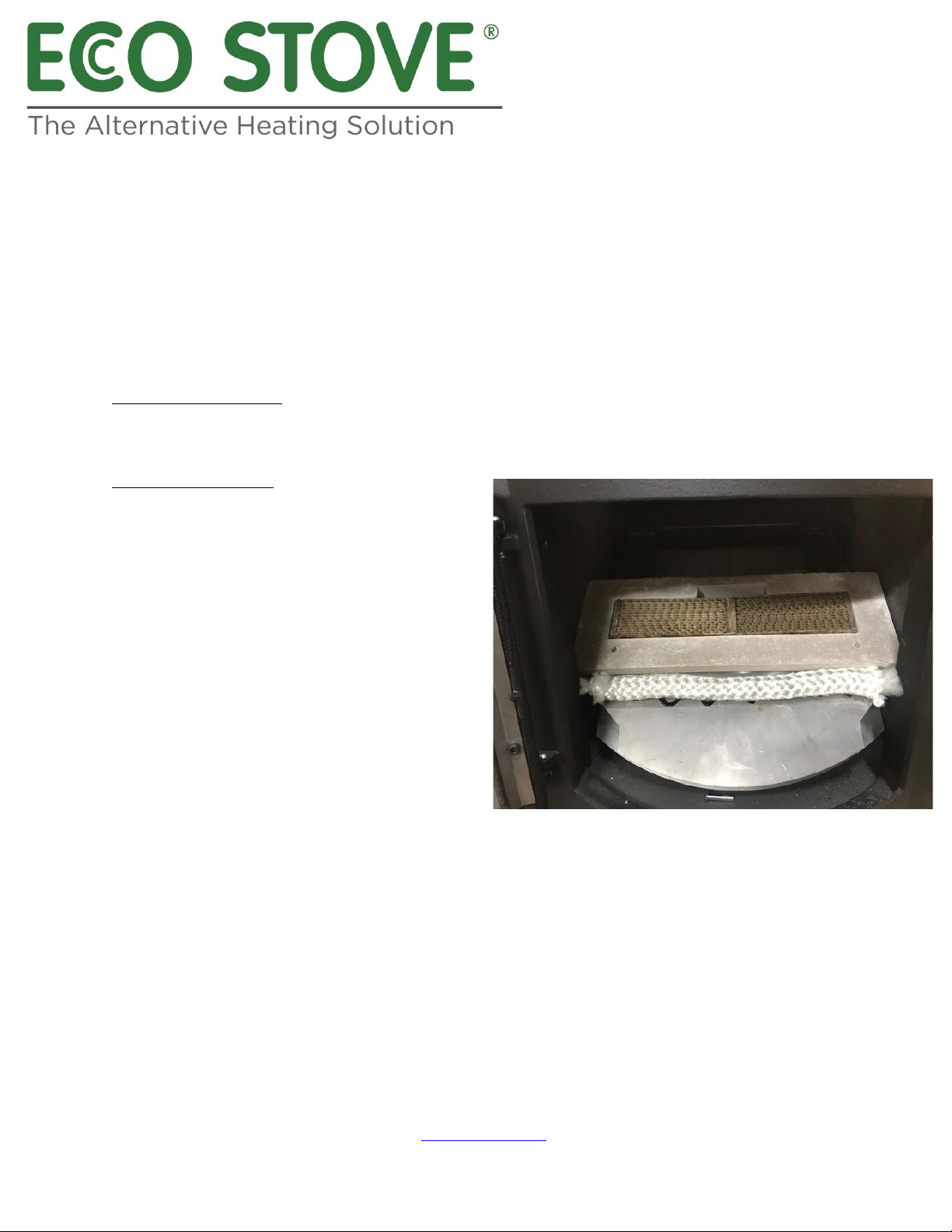
Cleaning the Catalysers
The catalyser can be viewed through the front left
and right cleaning plugs when the stove is not alight
or by removing the pins in the inner door frame
which holds the curve double leaf front of the baffle
up in place. Lift the weight of the baffle off the pins;
remove the pins and the baffle will hinge down and
rest on the stoves grate base section. The catalysers
can be vacuumed in place or lifted out and
vacuumed to ensure the dust entrapped is removed.
Replace the catalysers into their space in the baffle
brick and refit in reverse ensuring the 25mm rope is
in place both above the air box at the back and
25mm rope above the baffle front top.
THE CATALYSERS WILL ENTRAP DUST AND UNDERHEAVY USE MAY REQUIRE INSPECTION AND CLEANING
MONTHLY. This will be evidenced by performance or smoking back.
The catalyser will need replacing after two years or earlier dependent on usage and witnessed by a
breakdown of the cells within which will appear distorted and closed.
The Catalyser will gather dust and needs checking / cleaning monthly
Each month or so remove the pins and lower the underside baffle; vacuum the catalytic honeycomb
(catalyser) carefully and rehinge baffle and re-pin into place by fitting the pins beneath the curved edge
of the baffle into the door frame.

678/03.05.23/V2
P a g e | 13 of 28
Ecco Stove | Foster House | 2 Redditch Road | Studley | B80 7AX | United Kingdom
T| +44 (0) 1527 857 814 E| [email protected] W| www.eccostove.com
For all patents –See Addendum
14. EXTRA CONTROLS
Excessive draft over .006 inches of water gauge may be moderated by installing a draft diverter or
damper into the flue pipe off the top of the stove and duly balanced. Speak to your retailer for advice or
fitting.
The Ecco stove is equipped to accept an outside primary air facility which requires an extra tube
extension and back box for installation.
Dampers left open.
Operation with the air control or appliance dampers open can cause excess smoke. The appliance must
not be operated with air controls, appliance dampers or door left open except as directed in the
instructions.
15. ASH REMOVAL
Ash removal must only be carried out when the stove is not alight as by removing the ash draw would
overfire the appliance.
To remove ash collected in the ash draw, simply pull out the ash draw to its quarter extended position;
pull up safety catch lever on the side of the ash draw upon which the ash draw may be fully extracted
for cleaning.
Always re-fit the ash draw after emptying fully following the lighting / firing procedure at 21 C in this
instruction manual.
16. FUELS
16a Wood
Wood as a fuel must be maximum 20% moisture content and split logs are nominally 300mm maximum
in length and up to 60mm in cross section or below for best combustion, (measured at any one point
over the width of the split log) see 25h) for explanation.
Harder, more dense logs or wood will generally burn more slowly. Timber should be loaded flat across
the width of the stoves fire box to ensure the end grain does not release volatiles towards the glass door
and hence blacken it quickly.
Under no circumstances must the Eco stove be used as an incinerator to burn household or industrial
waste of any description –only untreated 20% humidity wood must be used.
Liquid fuels must not be burned on this appliance.

678/03.05.23/V2
P a g e | 14 of 28
Ecco Stove | Foster House | 2 Redditch Road | Studley | B80 7AX | United Kingdom
T| +44 (0) 1527 857 814 E| [email protected] W| www.eccostove.com
For all patents –See Addendum
Fuel Overloading - The maximum amount of fuel specified in this manual should not be exceeded,
overloading can cause excess smoke.
17. RE-FUELLING (for smoke control areas)
When the Eco Stove has been on a minimum or 2-3 hours burning, re-fuelling should either be carried
out with two or three split logs at each time, to ensure proper and complete combustion, and produce
minimum smoke. (Fuel loaded to be maximum 60mm cross section and 300 maximum length).
Ideally re-fuel on a bright fire. If the fire has burned down to sparse embers the stove may be re-fuelled
with two or three logs upon which the ash pit draw should be drawn out maximum 1 mm for 30 seconds
to create initial combustion, then closed to allow clean air controls (tertiary and air wash) to take over.
(Follow initial lighting procedures).
Smoke may escape the door if re-fuelling is carried out on a bright or lively fire if the stove body is below
150˚C. Open the door to the fire box slowly when re-fuelling to minimise smoke spillage into the room
as the door will create a vacuum drawing the smoke out of the fire box unless the flue ways are above
150°C. UNDER NO CIRCUMSTNCES MUST THE STOVE BE OPERATED WITH THE DOOR OPEN APART FOR
REFUELLING OTHERWISE EXCESSIVE SMOKE WILL BE PRODUCED.
Refuelling on to a low fire bed
If there is insufficient burning material in the firebed to light a new fuel charge, excessive smoke
emission can occur.Refuelling must be carried out onto a sufficient quantity of glowing embers and ash
that the new fuel charge will ignite in a reasonable period.If there are too few embers in the fire bed
add suitable kindling to prevent excess smoke.
18. TAR DEPOSITS
Tar deposits will not form in the stove or on its flue ways if adequately seasoned logs (below 25%
moisture content are used) and the stove generally burned above 150°C with a bright fire.
If tar deposits form in either the fire box or the flue way, the fuel being burned is not adequately
seasoned and damage will occur within the stove along with poor performance.
19. FLUE CONNECTION AND FLUE LININGS

678/03.05.23/V2
P a g e | 15 of 28
Ecco Stove | Foster House | 2 Redditch Road | Studley | B80 7AX | United Kingdom
T| +44 (0) 1527 857 814 E| [email protected] W| www.eccostove.com
For all patents –See Addendum
Under no circumstances should the diameter of any flue or lining leaving the stove
be reduced less than its 150mm diameter flue outlet.
The flue outlet on the stoves top is 150mm+ and accepts a 150mm stove pipe which
must be bedded into the outlet with fire cement for a gas tight seal (Minimum 1mm
thick metal pipe). Ensure a heat expansion joint is used as metal expands at a
different rate to Silicon Carbide and may result in cracking around the flue which
would not be covered under the guarantee.
The nominal flue outlet of the Ecco Stove is 150 mm diameter for which a 150 mm
flue liner insulated around within the masonry chimney with perlite grains or similar
or rockwool wrap is strongly advised, or a suitably insulated pre-fabricated twin
wall stainless steel flue system.
Any joints must be self tap screwed and jointed with fire cement.
Flue’s up to 9m in height are adequate in 150 mm inner diameter.
Flues over 9m in height should be 175 mm in the diameter.
High temperature hot face inner linings or coatings are suitable materials but ideally with a maximum
flue area of 225 x 225 mm.
Pumice hot face linings with insulation or leka pelletts are suitable.
Under no circumstances should the Ecco Stove be connected directly to clay linings within chimneys,
unless those clay liners have a hot face lining fitted within, in order to reduce condensation within the
chimney flue.
ANY FLUE INTENDED FOR USE MUST BE SWEPT IN ADVANCE AND TESTED FOR SUITABILITY PRIOR TO
THE APPLIANCE BEING INSTALLED. IF INSTALLINGTHIS STOVE ONTO AN EXISTING FLUE WHICH IS
DEEMED/TESTED AS SUITABLE WHICH WAS PREVIOUSLY USED FOR AN OPEN FIRE, THE FLUE MUST BE
SWEPT AGAIN WITHIN A MONTH OF INSTALLATION AS THE HGIHER TEMPERATURE OF FLUE GASES
MAY LOOSEN THE OLD OPEN FIRES BUILT UP DEPOSITS, TO ENSURE BLOCKAGE DOESN’T OCCUR.
20. CLEANING AND MAINTENANCE
Flue ways within the Eco Stove should be cleaned two monthly in continuous combustion for which the
stove should be let out (not burning).
Cleaning access points are located on the stoves top surface (4 hot plates) which must be lifted vertically
to access the vertical flue ways (2 each side).
After brushing down (and up) the deposits can be scraped or vacuumed out by removing the clearing
plugs located on the front of the bottom section (2 discs).
The first section of flue pipe vertically off the appliances top flue outlet MUST include a flue cleaning
access.

678/03.05.23/V2
P a g e | 16 of 28
Ecco Stove | Foster House | 2 Redditch Road | Studley | B80 7AX | United Kingdom
T| +44 (0) 1527 857 814 E| [email protected] W| www.eccostove.com
For all patents –See Addendum
Clean down through this into the stoves top; brush along the top flue chamber beneath the flue outlet
and vacuum out that chamber by sliding a flexible vac hose to left and right.
Seasonal Use. During a period when the stove will not be fired for example, during the summer
period, leave the ash pit door open, 2mm, to minimise condensation build up within the stove.
Clean the flue ways as described in the previous paragraphs (20. Cleaning and Maintenance) and
clean out both the ashtray and fire box. You may oil the outer paint surface with a light mist of
releasing oil, similar to WD40 and leave for the next heating season.
Check the rear back baffle boards and replace if cracked or broken.
Check all seals are fixed firmly in place on the door; ash pit front and cleaning plugs.
Remove and or clean above the steel gull wing baffle plate in the top of the firebox.
Ensure the chimney flue and stove pipe are swept early summer time or after stoves shut down
for the summer.
Oil the door hinges and door catch mechanism all in readiness for the new heating season.
a) Adverse flue conditions (downdraught or pressurisation) will result in poor performance; door
glass blackening and sooting in the flue ways. Such conditions must be rectified by improving
flue performance immediately. Clean any tar/deposits off the door glass.
b) Repairs or replacements must be carried out by a competent engineer.
Flueways are accessed by removing the cleaning plugs at a+ b + c + d and brushing vertically with the
flue brush provided.
Horizontal flue ways should be cleaned via the cleaning plugs at a + b + c + d and debris swept down in
to the vertical flue ways.
After cleaning vertically and horizontally the cleaning plugs at c and b should be removed and cleaned
out with a vacuum cleaner or suction hose.
Lastly remove the gull wing baffle at g and shake off –slide the whole assembly toward the rear of the
stove and then left or right to drop down. Re-instate in reverse order.
Always check the flue is clear after a prolonged period of shutdown or non use.
Vertical side flueways are cleaned through the top cleaning plugs along with the flue channels under the
head of the stove through those self same plugs and soot / deposits should be vacuumed out through
the face lower cleaning plugs to remove the debris cleaned down. These plugs must always be re-fitted
firmly in place before lighting or whilst running the Eco Stove. The firebox door and ash pit door should
remain closed at all times other than re-fuelling (fire box door) and ash pit door after following the
lighting and re-fuelling procedures stated in these instructions.
The Grate should be de-ashed by raking through the fire box door to ensure combustion air can flow
through the grate bars (only carry out these works when the stove is not alight).
The stove is now ready for re-use after all cleaning plugs have been re-fitted.

678/03.05.23/V2
P a g e | 17 of 28
Ecco Stove | Foster House | 2 Redditch Road | Studley | B80 7AX | United Kingdom
T| +44 (0) 1527 857 814 E| [email protected] W| www.eccostove.com
For all patents –See Addendum
The door glass may be cleaned of either grey transparent fly ash deposits or tar deposits from its inner
surface with a proprietary glass cleaner available from your retailer.
21. PAINT FINISHES
Paint finishes on your Eco Stove may produce a heavy chemical smell for a number of initial firings from
being newly painted.
You may colour co-ordinate your Eco Stove by painting its outer surfaces with non oil based or non-
flammable paints. (Certain paints may discolour however) .
22. ASSEMBLY
The Ecco Stove is delivered in 7 main structural parts: bottom section, grate section, left and right sides,
back section, baffle brick and top section.
Secondary points are two rear baffles (Vermiculite); vermiculite spacer blocks; one fixed front grate
plug. Two slide in vermiculite flueway dividers for left and right sides; one cast iron grate;
Eleven further non-structural parts are included being door section and frame; ash can; two lower
bottom section cleaning plugs; 4 top section cleaning plugs and 1 front lower top section airwash control
with spinner.
Six inner components are separate being back vermiculite tertiary airwash boards (two) and upper steel
top baffle.
One flue cleaning brush, one operating tool and one thermometer are included.
22a) HEARTH CONSTRUCTIONAL
The Eco Stove must stand on a load bearing hearth capable of carrying 500 kg with an overall width of
678mm and depth of 525mm (allowing 50mm gap behind the stove) or to suit in-country requirements
if different from the above.
22b) HEARTH (DECORATIVE)
Must extend 150mm either side or 225 mm in front of the Eco Stove as a minimum or to suit in country
requirements if different from the above.
APPLIANCE ASSEMBLY
Items shown with an * should be lifted in with a proprietary lifting frame.
All other items should be lifted by two or more people.

678/03.05.23/V2
P a g e | 18 of 28
Ecco Stove | Foster House | 2 Redditch Road | Studley | B80 7AX | United Kingdom
T| +44 (0) 1527 857 814 E| sales@eccostove.com W| www.eccostove.com
For all patents –See Addendum
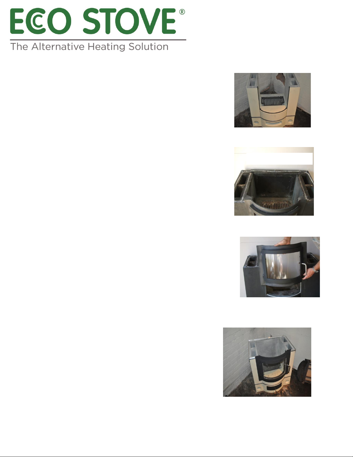
PARTS
A* LOWER BOTTOM PART
To be placed on level structural hearth, this section must be laid
level and minimum 50 mm from rear wall or if combustible. (The
circular hole at the rear of the appliance must remain plugged with
the
vermiculite plug fitted).
PHOTOGRAPH 1 Position the ‘T’ shaped joint seal/trim onto the top
horizontal face ready for the next layer to hold in place.
B GRATE SECTION
This inner section is lowered into Part A and the cast iron grate fitted
within. (No seals are fitted to this part). Ensure it is located on its domed
carbide locating pips by shuffling to bed into place.
Ba. Fit the cast iron grate into the recess within the Silicon Carbide
grate section.
C LEFT SIDE
This section to be stood firmly onto Part A using the locating pips to
position accurately. Ensure this section neatly holds the joint seal / trim
into place. Shuffle it to bed into its carbide locating pips.
E BACK SECTION
Aa POSITION TRIM (no trim with trimless models)
Ab Slide the ash can assembly into the opening in the lower
bottom part.
Ac Fit the two smaller cleaning plugs into the holes on the
Front of the lower bottom part.
D RIGHT SIDE
This section to be stood firmly onto Part A using the locating pips
to position accurately. Ensure this section neatly holds the joint
seal/trim into place. Shuffle it to bed onto its carbide locating pips.
678/03.05.23/V2
P a g e | 19 of 28
Ecco Stove | Foster House | 2 Redditch Road | Studley | B80 7AX | United Kingdom
T| +44 (0) 1527 857 814 E| sales@eccostove.com W| www.eccostove.com
For all patents –See Addendum
The back section has a tapered base which fits into the taper on the
bottom section. Stand the back section carefully in place gently
wedging off the rear wall of the stoves chosen location until held
in position by the rear top section:
E. DOOR SECTION
Door section should now be lowered over the sides until it sits firmly and
squarely onto the bottom section. Seals must be fitted (10mm round rope)
into the groove down left and right hand sides and across the grate section
to enable the door frame to seal onto.
NOTE: The tertiary air intake hole should be at the
bottom and not the top of the back section. This hole is to be left
permanently open. Ensure the rear section locates down inside the
rear trim and doesn’t ride high on the trims flange.
F. POSITION TRIM (no trim with trimless model)
The ‘T’ shaped joint seal / trim onto the top horizontal face ready
for the next section to hold in place. This seal butts up to the door
frame left and right.
Steel baffle has air tubes linking it to the vermiculite
pre-drilled back boards to introduce hot air to mix with the air
wash/secondary burn process. The rear section of the steel baffle
must sit into the stoves back panel and house the vermiculite
back boards in front of its half box section.

678/03.05.23/V2
P a g e | 20 of 28
Ecco Stove | Foster House | 2 Redditch Road | Studley | B80 7AX | United Kingdom
T| +44 (0) 1527 857 814 E| [email protected] W| www.eccostove.com
For all patents –See Addendum
H. FLUEING.
The stove may be connected with a 150mm stove pipe to the flue it will
operate on SEE SECTION 19 (FLUE CONNECTIONS) The connecting stove pipe
pushes into the flue outlet. Ensure there is an adequate heat expansion joint
used such as ceramic glass tape and then sealed with fire cement.
I.
It will be necessary to beat the trims into shape for an improved fit to reduce gaps as each piece moulds
differently with each appliance.
CAUTION ONLY A RUBBER MALLETT MUST BE USED.
THE STOVE MAY NOW BE LIT
23.
MODEL 678EC
TECHNICAL SLOW HEAT RELEASE APPLIANCE BS15250
a) Outputs:
G. Fit the four cast iron or alloy cleaning plugs into place.
Important: Wherever seals are fitted the installer must ensure
they are fixed firmly in place before locating each part with its
previous part without the use of cements or mastics
This manual suits for next models
1
Table of contents
Other ECCO STOVE Stove manuals


Popular Stove manuals by other brands

Ducasa
Ducasa SCANDY 7 INSTALLATION, USAGE AND MAINTENANCE MANUAL

Regency
Regency F2500 manual

PENTAGAST
PENTAGAST cookmax CXE498AQ operating instructions

Kingsman
Kingsman FV5000 installation instructions

Harman Stove Company
Harman Stove Company TLC 2000 Stove Installation & operating manual

Stanley
Stanley Argon Arranmore Installation and operating instructions

Bayou Classic
Bayou Classic PS100 owner's manual

RAIS
RAIS 600 Series Manual guide

JAYLINE
JAYLINE UL200 Owner operating instructions

Coleman
Coleman Camp Stove 413G Directions for operating and servising

Dovre
Dovre 500e Installation and operating manual

De Vielle
De Vielle DEF979415 Installation instructions manual


