Ecco Reflex 5590 Series Owner's manual

Page 1 of 7
Specications:
Size: 5590XXX 15” x 9” x 2.5”
5590XXX-VM 15” x 9” x 3.1”
5590XXX-MG 15” x 9” x 2.7”
5597XXX 15” x 9” x 2.5”
5597XXX-VM 15” x 9” x 3.1”
5597XXX-MG 15” x 9” x 2.7”
Weight: Permanent mount approx. 4.0 lbs.
Vacuum-Magnet Mount approx. 6.3 lbs.
Magnet Mount approx. 6.25 lbs.
Input Voltage: 12 to 48 VDC systems
Current Draw:
Maximum power consumption:
5590/5597: 6.0 Amps Maximum
Maximum power consumption: 84 watts
Flash Rate:
See Flash Pattern Chart
Temp. Range: -30ºC to +50ºC
Installation & Mounting:
Carefully remove the Minibar and place it on a at surface. Examine the
unit for transit damage, and locate all parts. If damage is found, or parts
are missing, contact the transit company or ECCO. Do not use damaged or
broken parts.
Installation and Operation Instructions
5590 Series LED Minibars
IMPORTANT! Read all instructions before installing and using. Installer: This manual must be delivered to the end user.
WARNING!
Failure to install or use this product according to manufacturer’s recommendations may result in property damage, serious injury, and/
or death to those you are seeking to protect!
Do not install and/or operate this safety product unless you have read and understood the safety information
contained in this manual.
1. Proper installation combined with operator training in the use, care, and maintenance of emergency warning devices are essential to
ensure the safety of emergency personnel and the public.
2. Emergency warning devices often require high electrical voltages and/or currents. Exercise caution when working with live electrical
connections.
3. This product must be properly grounded. Inadequate grounding and/or shorting of electrical connections can cause high current arcing,
which can cause personal injury and/or severe vehicle damage, including re.
4. Proper placement and installation is vital to the performance of this warning device. Install this product so that output performance of
the system is maximized and the controls are placed within convenient reach of the operator so that they can operate the system without
losing eye contact with the roadway.
5. Do not install this product or route any wires in the deployment area of an air bag. Equipment mounted or located in an air bag
deployment area may reduce the eectiveness of the air bag or become a projectile that could cause serious personal injury or death.
Refer to the vehicle owner’s manual for the air bag deployment area. It is the responsibility of the user/operator to determine a suitable
mounting location ensuring the safety of all passengers inside the vehicle particularly avoiding areas of potential head impact.
6. It is the responsibility of the vehicle operator to ensure daily that all features of this product work correctly. In use, the vehicle operator
should ensure the projection of the warning signal is not blocked by vehicle components (i.e., open trunks or compartment doors),
people, vehicles or other obstructions.
7. The use of this or any other warning device does not ensure all drivers can or will observe or react to an emergency warning signal.
Never take the right-of-way for granted. It is the vehicle operator’s responsibility to be sure they can proceed safely before entering an
intersection, drive against trac, respond at a high rate of speed, or walk on or around trac lanes.
8. This equipment is intended for use by authorized personnel only. The user is responsible for understanding and obeying all laws
regarding emergency warning devices. Therefore, the user should check all applicable city, state, and federal laws and regulations. The
manufacturer assumes no liability for any loss resulting from the use of this warning device.
IMPORTANT! This unit is a safety device and it must be connected
to its own separate, fused power point to assure its continued
operation should any other electrical accessory fail.
CAUTION!
When drilling into any vehicle surface, make sure that the
area is free from any electrical wires, fuel lines, vehicle
upholstery, etc. that could be damaged.

Page 2 of 7
Permanent Mount:
1. Select the desired location on a at surface for the
Minibar to be mounted. The visibility of the ash and
ease of wiring access should be taken into
consideration in the selection of the mounting location.
2. Remove lens screws, then remove lens. Use the four holes
in the corners of the base to mark the mounting hole
locations.
3. Drill the holes using a 7/32” drill size.
4. A fth hole may be drilled for wire access.
5. Connect the power wires as shown in the wiring section
(see Figure 3).
6. Mount the minibar with M5 hardware provided.
Vacuum-Magnet Mount:
1. Remove round black stickers for vacuum placement
2. Remove lens screws, then remove lens.
3. Unclip and remove wire harness
4. Position vacuum magnets, place, and tighten screws.
5. Insert pinned end of cable through the wire harness hole
from the bottom of the base. Pull at least 6 inches of slack.
6. Turn pins crimp side up, and insert pins into connector as
shown in Figure 1.
7. Place zip-tie 1.0” from base of the connectors shown in
Figure 2. Zip-tie must not slide on cord.
8. Trim excess zip-tie.
9. Clip connector to the PCA board and pull slack until zip-tie
touches base.
10. Install lens, reverse of removal.
11. Slide o-ring onto screw until it reaches head, before placing
into lens. If o-rings are damaged, replace with new ones.
Vacuum Mount Installation for 5590 Series:
Figure 1
Figure 2
Wiring:
The wiring for the permanent mount minibar is as shown in Figure 3. All
wiring should be a minimum of 18AWG. The positive line must have a 10A
fuse, as shown. A switch may be used to control the on/o function.
Figure 3
The Vacuum-Magnet Mount feature includes suction cups on the bottom of the
minibar, with a magnet inside of the suction cup, for a secure, temporary mount.
The minibar should be placed in the center of the roof where the least amount of
curvature occurs. Before installing, make sure the mounting surface is clean and
there is no debris on the bottom of the minibar or on the roof of the vehicle, which
could reduce the holding power of the suction cup and magnet. Place and remove
the minibar without sliding to avoid scratching the paint on the vehicle. After
placement, the minibar should adhere rmly to the surface. If the unit slides or
moves easily, a proper installation has not been obtained. To release the vacuum,
lift the tab to release the airlock (see Figure 4). To protect the Vacuum-Magnet
Mount assembly, return minibar to the box when not in use. Do not attempt to
attach the minibar to an ice-covered surface.
Figure 4
Flash Mode Selection:
Flash patterns can be selected on permanent mount minibars by touching the
BLUE wire to the BLACK power wire for less than a second. Contacting the BLUE
and BLACK wires for longer than a second toggles to the preceding ash pattern.
The VM and MG mount models have ash pattern select via a momentary switch
on the cigarette plug.
Flash Pattern Synching
The 5590 and 5597 permanent mount models sync with other compatible ECCO
products via the yellow wire:
1. Determine the desired style of ash pattern for each unit and set each unit in-
dividually (without the YELLOW wires connected together) to avoid confusion.
It is also strongly recommended that the same style of ash pattern be used
on all units to produce the most eective warning pattern. (NOTE: Phases
A and B for each style of ash pattern in the table denote the relative timing
between units connected in a synchronizing installation. To operate simultane-
ously, each unit must be set to the same phase (A + A or B + B); to operate
alternately, units must be set to have the opposite phase (A + B or B + A)).
2. Connect the YELLOW (SYNC) wires together and check that the units are
ashing in a synchronized manner as expected. If a pattern on one module
appears to be wrong, the BLUE (PATTERN SET) wire can be used to cycle
forward or backward on that individual unit until the correct pattern is selected.
Note: This will only change the pattern in the one unit and will not aect
the other units connected to the YELLOW (SYNC) wire.
3. If the YELLOW wire is unused, leave unconnected and insulated.
IMPORTANT! Disable power before wiring up the Minibar.
NOTE: Operating the vehicle without the outer lens installed
on the product may result in damage that will NOT be
covered under warranty.
RED
SWITCH
(USER SUPPLIED)
FUSE (10A)
(USER SUPPLIED)
GROUND
SWITCH
(USER SUPPLIED)
WHITE
(DUAL COLOR
ONLY)
FLASH PATTERN SELECT
(MOMENTARY TO GROUND)
DIMMING (+)
BLUE
YELLOW
SYNC
BLACK
GROUND
Dimming Feature
The 5590 has the ability to dim the lightbars light output, which may be useful
when using the lightbar at night. To activate the dimming feature, connect the
blue wire to fused battery power (+). This can be done using a switch provided
by the user.
WHITE Wire Operation (Dual Color Models Only)
The 5590 dual color models have an additional WHITE wire which can be used
to easily select between two desired ash patterns. To use this option, power the
lightbar with the RED wire and select the desired ash pattern from the list below.
For example, “Single Color 1 Phase 1”. Remove power from the RED wire. Apply
power to the WHITE wire and select the desired ash pattern from the list below.
For example, “SAE/T13 Triple Color 2 Phase 1”. Now anytime the RED wire is
powered the lightbar will ash the “Single Color 1 Phase 1” pattern and anytime
the WHITE wire is powered the lightbar will ash the “SAE/T13 Triple Color 2
Phase 1” pattern. Any pattern from the list can be assigned to either wire.
PIN 1-RED
PIN 3-BLUE
PIN 4-WHITE
PIN 5-BLACK

Page 3 of 7
1. Refer to the appropriate Vacuum Mount Installation for
the 5500 series, steps 2 through 9, and the corresponding
Figures for wiring instructions for the cord.
2. Place hex nut into the hex shaped retaining cavity on the
inside of the minibar base.
3. Place an internal star washer onto the enclosed M5 x 20
hex bolt and insert the hex bolt through the hole in the cup
magnet as shown. Hold the magnet/bolt assembly with the
bolt extended through the magnet as far as possible and
feed the hex nut and the shank of the bolt through one
of the openings at the 4 corners of the underside of the
minibar base. Maintain tension on the bolt/nut by holding
onto the cup magnet while tightening the assembly. Repeat
this process for all four corners. See Figure 5.
4. Place the adhesive magnet covers over the magnets.
5. Replace the lens.
Magnet Mount Installation for 5590 Series:
Figure 5
Operator is responsible for ensuring auxiliary plug
ts correctly into auxiliary power plug outlet used.
For proper operation, verify auxiliary power outlet
circuit is rated to supply a minimum of 10 amps.
(See specications section for rated current in
amperes).
Do not exceed the current rating for the auxiliary
power outlet recommended by vehicle manufac-
turer.
Keep auxiliary plug and outlet clean and free of
debris.
Do not use the auxiliary plug when wet.
Insert auxiliary plug fully into the outlet for proper
connection.
Grasp auxiliary plug, NOT cord, to remove from
outlet.
Remove auxiliary plug completely from outlet when
light is not in use.
WARNING!
Maximum recommended vehicle speed for safe operation
using the Vacuum Mount model is 65 mph (104 km/h) when
tted to the center of a vehicle roof of steel construction. Higher
speeds could cause the mount to fail, resulting in the minibar ying
o of the vehicle, which could cause damage to other vehicles and
injury or death to the passengers. The vacuum-magnet mount is
not intended as a permanent mount for the minibar. The vacuum-
magnet mount unit must be mounted on a magnetic surface (i.e. no
berglass, etc.). Ensure that the magnet ts kept clean.
Note: The Magnet Mount is not recommended for use on a
moving vehicle, nor is it inteded as a permanent mount for
the light. Long duration usage of the magnet in the presence
of moisture will cause the steel to rust.
WARNING!
Failure to follow these instructions can result in re
or injury from excessive heat build up.

Page 4 of 7
Pattern Mode Description Sync FPM SAEJ845 CAT13
1SingleFlashPhase1(DEFAULT) Yes YES YES
2 SingleFlashPhase2 Yes YES YES
3 SingleFlashAlternatingSplit Yes NO YES
4 SingleFlashPhase1Yes YES NO
5 SingleFlashPhase2 Yes YES NO
6 SingleFlashAlternatingSplit Yes NO NO
7 DoubleFlashPhase1 Yes YES YES
8 DoubleFlashPhase2 Yes YES YES
9 DoubleFlashAlternatingSplit Yes NO YES
10 DoubleFlashPhase1 Yes YES NO
11 DoubleFlashPhase2 Yes YES NO
12 DoubleFlashAlternatingSplit Yes NO NO
13 QuadFlashPhase1 Yes YES YES
14 QuadFlashPhase2 Yes YES YES
15 QuadFlashAlternatingSplit Yes NO YES
16 QuadFlashPhase1 Yes YES NO
17 QuadFlashPhase2 Yes YES NO
18 QuadFlashAlternatingSplit Yes NO NO
19 TripleFlashPhase1 Yes YES YES
20 TripleFlashPhase2 Yes YES YES
21 TripleFlashAlternatingSplit Yes NO YES
22 QuintFlashPhase1 Yes YES NO
23 QuintFlashPhase2 Yes YES NO
24 QuintDiagonalRotate Yes NO NO
25 DoubleDiagonalPhase1 Yes YES NO
26 DoubleDiagonalPhase2 Yes YES NO
27 DoubleDiagonalRotate Yes NO NO
28 QuadDiagonalPhase1 Yes YES NO
29 QuadDiagonalPhase2 Yes YES NO
30 QuadDiagonalRotate Yes NO NO
11 31 FastRotate Yes 120 NO NO
12 32 Rotate/Quad Yes 150/75 NO NO
13 33 WaveRotate Yes 70 NO NO
14 34 Random No NO NO
15 35 SteadyBurn No NO NO
10 150
3 75
4 120
5 75
1 75
2 120
9 150
SINGLECOLORFLASHPATTERNCHAR
T
6 120
7 75
8 150

Page 5 of 7
Pattern Mode1 Mode2 Mode1+2 Description Sync Phase FPM SAEJ845 CAT13
1 1 SAE/T13SingleColor1Phase1(DEFAULT) Yes A YES YES
2 2 SAE/T13SingleColor1Phase2 Yes B YES YES
3 SAE/T13SingleSplitColorPhase1 Yes A NO YES
4 SAE/T13SingleSplitColorPhase2 Yes B NO YES
15 SAE/T13SingleColor2Phase1(DEFAULT) Yes A YES YES
26 SAE/T13SingleColor2Phase2 Yes B YES YES
3 3 7 SAE/T13SingleDualColorPhase1(DEFAULT) Yes A YES YES
4 4 8 SAE/T13SingleDualColorPhase2 Yes B YES YES
5 5 9 SAE/T13SingleAlternatingSplitColor1&Color2 Yes NO YES
6 10 SingleColor1Phase1 Yes A YES NO
7 11 SingleColor1Phase2 Yes B YES NO
12 SingleSplitColorPhase1 Yes A NO NO
13 SingleSplitColorPhase2 Yes B NO NO
614 SingleColor2Phase1 Yes A YES NO
715 SingleColor2Phase2 Yes B YES NO
8 8 16 SingleDualColorPhase1 Yes A YES NO
9 9 17 SingleDualColorPhase2 Yes B YES NO
10 10 18 SingleAlternatingSplitColor1&Color2 Yes NO NO
11 19 SAE/T13DoubleColor1Phase1 Yes A YES YES
12 20 SAE/T13DoubleColor1Phase2 Yes B YES YES
21 SAE/T13DoubleSplitColorPhase1 Yes A NO YES
22 SAE/T13DoubleSplitColorPhase2Yes B NO YES
11 23 SAE/T13DoubleColor2Phase1 Yes A YES YES
12 24 SAE/T13DoubleColor2Phase2 Yes B YES YES
13 13 25 SAE/T13DoubleDualColorPhase1 Yes A YES YES
14 14 26 SAE/T13DoubleDualColorPhase2 Yes B YES YES
15 15 27 SAE/T13DoubleAlternatingSplitColor1&Color2 Yes NO YES
16 28 ECER65/SAEDoubleColor1Phase1 Yes A YES NO
17 29 ECER65‐SAEDoubleColor1Phase2 Yes B YES NO
30 ECER65/SAEDoubleSplitColorPhase1 Yes A NO NO
31 ECER65/SAEDoubleSplitColorPhase2 Yes B NO NO
16 32 ECER65/SAEDoubleColor2Phase1 Yes A YES NO
17 33 ECER65/SAEDoubleColor2Phase2 Yes B YES NO
18 18 34 ECER65/SAEDoubleDualColorPhase1 Yes A YES NO
19 19 35 ECER65/SAEDoubleDualColorPhase2 Yes B YES NO
20 20 36 ECER65/SAEDoubleAlternatingSplitColor1&Colo
r
Yes NO NO
21 37 SAE/T13TripleColor1Phase1 Yes A YES YES
22 38 SAE/T13TripleColor1Phase2 Yes B YES YES
39 SAE/T13TripleSplitColorPhase1 Yes A NO YES
40 SAE/T13TripleSplitColorPhase2 Yes B NO YES
21 41 SAE/T13TripleColor2Phase1 Yes A YES YES
22 42 SAE/T13TripleColor2Phase2 Yes B YES YES
23 23 43 SAE/T13TripleDualColorPhase1 Yes A YES YES
44 SAE/T13TripleDualColorPhase2 Yes B YES YES
24 24 45 SAE/T13TripleAlternatingSplitColor1&Color2 Yes NO YES
25 46 SAE/T13QuadColor1Phase1 Yes A YES YES
26 47 SAE/T13QuadColor1Phase2 Yes B YES YES
48 SAE/T13QuadSplitColorPhase1 Yes A NO YES
49 SAE/T13QuadSplitColorPhase2 Yes B NO YES
25 50 SAE/T13QuadColor2Phase1 Yes A YES YES
26 51 SAE/T13QuadColor2Phase2 Yes B YES YES
27 27 52 SAE/T13QuadDualColorPhase1 Yes A YES YES
28 28 53 SAE/T13QuadDualColorPhase2 Yes B YES YES
29 29 54 SAE/T13QuadAlternatingSplitColor1&Color2 Yes NO YES
1 75
2 120
3 75
4 120
5 75
6 75
DUALCOLORFLASHPATTERNCHART

Page 6 of 7
Pattern Mode1 Mode2 Mode1+2 Description Sync Phase FPM SAEJ845 CAT13
30 55 ECER65/SAEQuadColor1Phase1 Yes A YES NO
31 56 ECER65/SAEQuadColor1Phase2 Yes B YES NO
57 ECER65/SAEQuadSplitColorPhase1 Yes A NO NO
58 ECER65/SAEQuadSplitColorPhase2 Yes B NO NO
30 59 ECER65/SAEQuadColor2Phase1 Yes A YES NO
31 60 ECER65/SAEQuadColor2Phase2 Yes B YES NO
32 32 61 ECER65/SAEQuadDualColorPhase1 Yes A YES NO
33 33 62 ECER65/SAEQuadDualColorPhase2 Yes B YES NO
34 34 63 ECER65/SAEQuadAlternatingSplitColor1&Color
2
Yes NO NO
35 64 DoubleDiagonalAlternateColor1Phase1 Yes A NO NO
36 65 DoubleDiagonalAlternateColor1Phase2 Yes B NO NO
66 DoubleDiagonalAlternateSplitColorPhase1 Yes A NO NO
67 DoubleDiagonalAlternateSplitColorPhase2 Yes B NO NO
35 68 DoubleDiagonalAlternateColor2Phase1 Yes A NO NO
36 69 DoubleDiagonalAlternateColor2Phase2 Yes B NO NO
37 37 70 DoubleDiagonalAlternateDualColorPhase1 Yes A NO NO
38 38 71 DoubleDiagonalAlternateDualColorPhase2 Yes B NO NO
39 72 QuadDiagonalAlternateColor1Phase1 Yes A NO NO
40 73 QuadDiagonalAlternateColor1Phase2 Yes B NO NO
74 QuadDiagonalAlternateSplitColorPhase1 Yes A NO NO
75 QuadDiagonalAlternateSplitColorPhase2 Yes B NO NO
39 76 QuadDiagonalAlternateColor2Phase1 Yes A NO NO
40 77 QuadDiagonalAlternateColor2Phase2 Yes B NO NO
41 41 78 QuadDiagonalAlternateDualColorPhase1 Yes A NO NO
42 42 79 QuadDiagonalAlternateDualColorPhase2 Yes B NO NO
43 80 FastRotateColor1 Yes A NO NO
43 81 FastRotateColor2 Yes A NO NO
82 FastRotateDual(Color1thenColor2) Yes A NO NO
44 83 Rotate/QuadColor1Yes A NO NO
44 84 Rotate/QuadColor2 Yes A NO NO
85 Rotate/QuadDual(Color1thenColor2) Yes A NO NO
45 86 WaveRotateColor1 Yes A NO NO
45 87 WaveRotateColor2 Yes A NO NO
88 WaveRotateDual(Color1thenColor2) Yes A NO NO
13 89 Random‐Color1&Color2 NO NO NO
46 90 Steadyburn‐Color1 NO NO NO
46 91 Steadyburn‐Color2 NO NO NO
14
10 120
11 150/75
12 70
DUALCOLORFLASHPATTERNCHART
8150
9150
7 120

Page 7 of 7
Manufacturer Limited Warranty and Limitation of Liability:
Manufacturer warrants that on the date of purchase, this product will conform to Manufacturer’s specications for this product (which are
available from the Manufacturer upon request). This Limited Warranty extends for sixty (60) months from the date of purchase.
DAMAGE TO PARTS OR PRODUCTS RESULTING FROM TAMPERING, ACCIDENT, ABUSE, MISUSE, NEGLIGENCE, UNAPPROVED
MODIFICATIONS, FIRE OR OTHER HAZARD; IMPROPER INSTALLATION OR OPERATION; OR NOT BEING MAINTAINED IN ACCOR-
DANCE WITH THE MAINTENANCE PROCEDURES SET FORTH IN MANUFACTURER’S INSTALLATION AND OPERATING INSTRUC-
TIONS VOIDS THIS LIMITED WARRANTY.
Exclusion of Other Warranties:
MANUFACTURER MAKES NO OTHER WARRANTIES, EXPRESSED OR IMPLIED. THE IMPLIED WARRANTIES FOR MERCHANT-
ABILITY, QUALITY OR FITNESS FOR A PARTICULAR PURPOSE, OR ARISING FROM A COURSE OF DEALING, USAGE OR TRADE
PRACTICE ARE HEREBY EXCLUDED AND SHALL NOT APPLY TO THE PRODUCT AND ARE HEREBY DISCLAIMED, EXCEPT TO
THE EXTENT PROHIBITED BY APPLICABLE LAW. ORAL STATEMENTS OR REPRESENTATIONS ABOUT THE PRODUCT DO NOT
CONSTITUTE WARRANTIES.
Remedies and Limitation of Liability:
MANUFACTURER’S SOLE LIABILITY AND BUYER’S EXCLUSIVE REMEDY IN CONTRACT, TORT (INCLUDING NEGLIGENCE), OR
UNDER ANY OTHER THEORY AGAINST MANUFACTURER REGARDING THE PRODUCT AND ITS USE SHALL BE, AT MANUFAC-
TURER’S DISCRETION, THE REPLACEMENT OR REPAIR OF THE PRODUCT, OR THE REFUND OF THE PURCHASE PRICE PAID BY
BUYER FOR NON-CONFORMING PRODUCT. IN NO EVENT SHALL MANUFACTURER’S LIABILITY ARISING OUT OF THIS LIMITED
WARRANTY OR ANY OTHER CLAIM RELATED TO THE MANUFACTURER’S PRODUCTS EXCEED THE AMOUNT PAID FOR THE
PRODUCT BY BUYER AT THE TIME OF THE ORIGINAL PURCHASE. IN NO EVENT SHALL MANUFACTURER BE LIABLE FOR LOST
PROFITS, THE COST OF SUBSTITUTE EQUIPMENT OR LABOR, PROPERTY DAMAGE, OR OTHER SPECIAL, CONSEQUENTIAL,
OR INCIDENTAL DAMAGES BASED UPON ANY CLAIM FOR BREACH OF CONTRACT, IMPROPER INSTALLATION, NEGLIGENCE, OR
OTHER CLAIM, EVEN IF MANUFACTURER OR A MANUFACTURER’S REPRESENTATIVE HAS BEEN ADVISED OF THE POSSIBILITY
OF SUCH DAMAGES. MANUFACTURER SHALL HAVE NO FURTHER OBLIGATION OR LIABILITY WITH RESPECT TO THE PRODUCT
OR ITS SALE, OPERATION AND USE, AND MANUFACTURER NEITHER ASSUMES NOR AUTHORIZES THE ASSUMPTION OF ANY
OTHER OBLIGATION OR LIABILITY IN CONNECTION WITH SUCH PRODUCT.
This Limited Warranty denes specic legal rights. You may have other legal rights which vary from jurisdiction to jurisdiction. Some jurisdic-
tions do not allow the exclusion or limitation of incidental or consequential damages.
An ECCO SAFETY GROUP™ Brand
ECCOSAFETYGROUP.com
833 West Diamond St, Boise, Idaho 83705
Customer Service USA 800-635-5900
UK +44 (0)113 237 5340 | AUS +61 (0)3 63322444
ECCOESG.com
© 2012 ECCO, Inc. All rights reserved.
920-4300-00 Rev. H

Página 1 de 4
Especicaciones:
Tamaño 5590XXX 38,1 cm x 22,8 cm x 6,3 cm
(15 pulg. x 9 pulg. x 2.5 pulg.)
5590XXX-VM 38,1 cm x 22,8 cm x 7,9 cm
(15 pulg. x 9 pulg. x 3.1 pulg.)
5590XXX-MG 38,1 cm x 22,8 cm x 6,7 cm
(15 pulg. x 9 pulg. x 2.7 pulg.)
5597XXX 38,1 cm x 22,8 cm x 6,3 cm
(15 pulg. x 9 pulg. x 2.5 pulg.)
5597XXX-VM 38,1 cm x 22,8 cm x 7,9 cm
(15 pulg. x 9 pulg. x 3.1 pulg.)
5597XXX-MG 38,1 cm x 22,8 cm x 6,7 cm
(15 pulg. x 9 pulg. x 2.7 pulg.)
Peso: Montaje permanente aprox. 4 libras (1,8 kg.)
Montaje de vacío aprox. 6,3 libras (2,8 kg.)
magnético
Montaje magnético aprox. 6,25 libras (2,8 kg.)
Tensión de entrada: Sistemas de 12 a 24 V CC
Consumo de corriente:
5590/5597: 6.0 amperes máxima
Consumo máximo de energía: 84 vatios
Velocidad de destello:
Consulte la tabla de patrones de intermitencia
Rango de temp.: -30ºC a +50ºC
Instalación y montaje:
Retire la Minibar con cuidado y colóquela sobre una supercie plana.
Examine la unidad para detectar si se produjeron daños durante el
traslado y ubique todas las piezas. Si se encuentran daños o si faltan
piezas, comuníquese con la empresa de transporte o con ECCO. No
utilice piezas dañadas o rotas.
Instrucciones de instalación y operación
unidades Minibar LED serie 5590
¡ADVERTENCIA!
Si no sigue las instrucciones del fabricante a la hora de instalar o usar el producto, pueden producirse daños materiales, y lesiones
graves o incluso mortales a aquellos que pretende proteger!
No instale ni opere este producto de seguridad, a menos que haya leído y comprendido la información de
seguridad contenida en este manual.
1. Para garantizar su propia seguridad y la de las personas a las que intenta proteger, es esencial una instalación correcta, combinada con
la formación de operador en el uso, cuidado y mantenimiento de los dispositivos de alerta de emergencia.
2. Los dispositivos de advertencia de emergencia a menudo requieren altos voltajes y/o corrientes eléctricas. Tenga cuidado cuando
manipule conexiones eléctricas con corriente.
3. Este producto debe estar conectado a tierra correctamente. Una conexión a tierra incorrecta o unas conexiones eléctricas
cortocircuitadas pueden provocar arcos de corriente alta, lo que puede ocasionar lesiones personales o daños graves en el vehículo,
incluso un incendio.
4. La colocación e instalación adecuadas son vitales para el buen funcionamiento de este dispositivo de alarma. Instale este producto
de forma que permita un rendimiento óptimo del sistema y los controles estén situados de modo que el operador pueda alcanzarlos
cómodamente y manejar el sistema sin perder en ningún momento el contacto visual con la calzada.
5. No instale este producto ni coloque los cables en la zona de despliegue de un airbag. Si el equipo se monta o coloca en la zona de
despliegue de un airbag, el airbag perderá ecacia o el equipo puede salir despedido, lo cual puede causar lesiones graves o incluso
mortales. Consulte el manual del propietario del vehículo para conocer la zona de despliegue de los airbags. El usuario u operador son
responsables de determinar una posición de montaje adecuada que garantice la seguridad de todos los ocupantes del vehículo, y deben
evitar zonas que puedan provocar golpes en la cabeza.
6. Es responsabilidad del operador del vehículo asegurarse de que todas las características de este producto funcionan correctamente
durante su uso. Durante su uso, el operador del vehículo debe asegurarse de que no haya componentes del vehículo (como los maleteros
o puertas del habitáculo abiertos), personas, vehículos u otros obstáculos que bloqueen la señal de alarma.
7. El uso de este o cualquier otro dispositivo de alarma no garantiza que los conductores puedan o quieran observar o reaccionar a la señal
de alarma. Nunca dé por hecho que tiene prioridad de paso. Es responsabilidad enteramente suya asegurarse de que puede continuar
de forma segura antes de entrar en una intersección, conducir en sentido contrario, responder a una gran velocidad o caminar por los
carriles de tráco o cerca de ellos.
8. El uso de este equipo está destinado exclusivamente a personal autorizado. El usuario es responsable de conocer y acatar todas las
leyes vigentes relacionadas con dispositivos de señales de advertencia. Por lo tanto, el usuario debe comprobar todas las leyes y
normativas de ámbito metropolitano, regional, nacional y cualquier otro ámbito pertinente. El fabricante no asume responsabilidad alguna
por pérdidas derivadas del uso de este dispositivo de alarma.
¡IMPORTANTE! Lea todas las instrucciones antes de instalar y utilizar. Instalador: Este manual se debe entregar al usuario nal.
¡Importante! Esta unidad es un dispositivo de seguridad y debe
conectarse a su propia alimentación con fusible, para garantizar
una operación continua en el caso de que falle cualquier otro
accesorio eléctrico.

Página 2 de 4
Montaje permanente:
1. Seleccione la ubicación de montaje deseada para la Minibar sobre
una supercie plana. Al seleccionar la ubicación del montaje se
deben tener en cuanta la visibilidad de la luz intermitente y la
facilidad de acceso al cableado.
2. Desatornille el lente de la base de la Minibar. Utilice los cuatro
oricios de las esquinas de la base para marcar las ubicaciones
de los oricios de montaje.
3. Perfore los oricios con un taladro de 5,55 mm (7/32 pulg.).
4. Se puede perforar un quinto oricio para el acceso del cable.
5. Conecte los cables de alimentación como se indica en la sección
de cableado (vea la gura 3).
6. Realice el montaje de la Minibar con los herrajes M5 provistos.
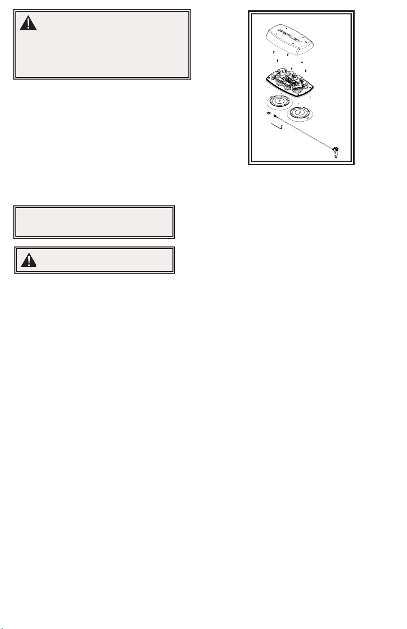
1. Retire los adhesivos redondos negros para colocar el vacío.
2. Extraiga los tornillos del lente y luego extraiga el lente.
3. Suelte y retire el arnés de cableado.
4. Ubique los imanes de vacío, coloque y ajuste los tornillos.
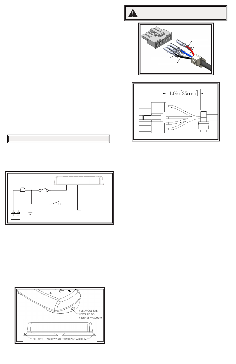
5. Inserte el extremo con pines del cable a través del oricio del arnés
de cableado desde la parte inferior de la base. Tire al menos 15 cm (6
pulgadas) de cable suelto.
6. Gire hacia arriba el conector del pin e inserte los pines en el conector
como se muestra en la gura 1.
7. Coloque la abrazadera plástica de 2,5 cm (1 pulg.) desde la base de
los conectores según se muestra en la gura 2. La abrazadera plástica
no debe deslizarse sobre el cable.
8. Recorte el exceso de abrazadera.
9. Sujete el conector a la placa PCA y tire el cable suelto hasta que la
abrazadera plástica toque la base.
10. Instale el lente. Siga el procedimiento inverso a la extracción.
11. Deslice el o-ring sobre el tornillo hasta la cabeza antes de colocarlo en el
lente. Si los o-ring están dañados, cámbielos por nuevos.
Instalación con montaje en vacío para la serie 5590:
NOTA:
El uso del vehículo sin el lente exterior instalado en el producto
puede ocasionar un daño que NO se encuentra cubierto por
la garantía.
!
Cableado:
El cableado de la Minibar de montaje permanente es el que se muestra
en la gura 3. Todo el cableado debe ser como mínimo 18 AWG. La línea
positiva debe tener un fusible de 7.5 amperes, según se indica. Se puede
utilizar un interruptor para controlar la función de encendido-apagado.
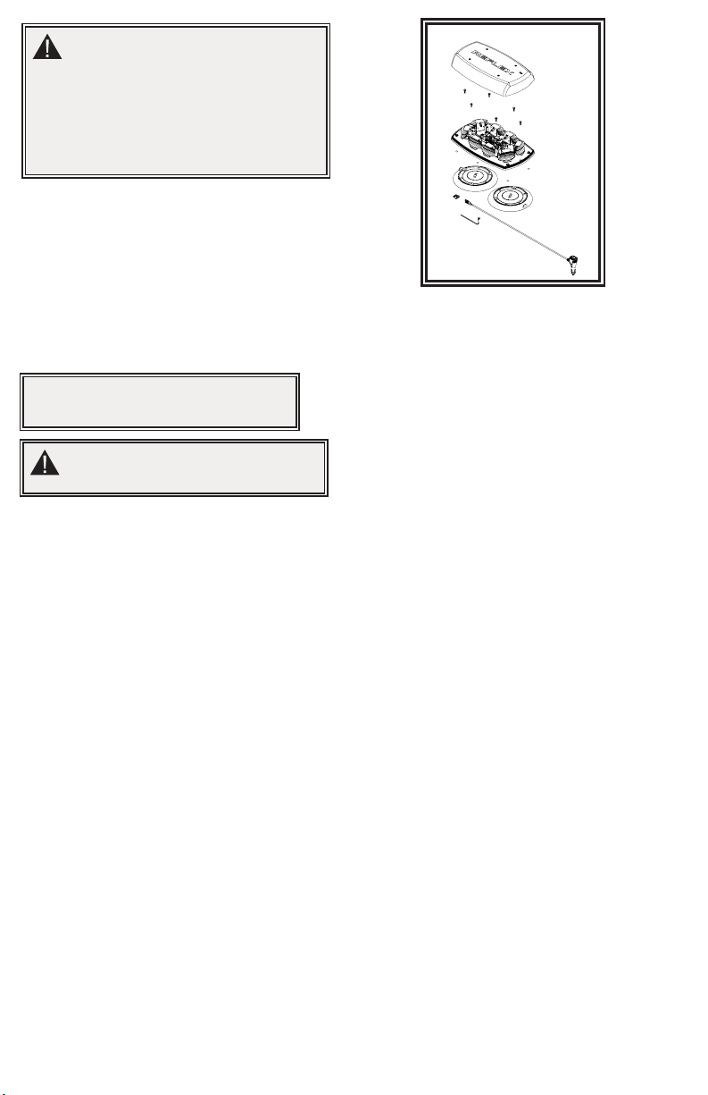
Montaje de vacío magnético:
La característica de montaje de vacío magnético incluye ventosas de succión
en la parte inferior de la Minibar, con un imán dentro de la ventosa para lograr
un montaje temporario y seguro. La Minibar debe colocarse en el centro del
techo donde se produce la menor cantidad de curvatura. Antes de la instalación,
asegúrese de que la supercie de montaje esté limpia y que no haya residuos en
la parte inferior de la Minibar ni sobre el techo del vehículo, lo que podría reducir
el poder de sujeción del imán y de la ventosa de succión. Coloque y retire la
Minibar sin deslizarla para evitar rayar la pintura del vehículo. Luego de ubicarla,
la Minibar debe adherirse rmemente a la supercie. Si la unidad se desliza o se
mueve con facilidad, no se ha logrado una instalación correcta. Para liberar el
vacío, levante la pestaña para liberar la cámara de aire (vea la gura 4). Coloque
la Minibar en la caja cuando no la utilice para proteger el conjunto de montaje
de vacío magnético. No intente colocar la Minibar sobre una supercie
recubierta de hielo.
Figura 4
Figura 3
ROJO
TIERRA TIERRA
INTERRUPTOR (7,5A)
(PROVISTO POR EL USUARIO)
INTERRUPTOR
(PROVISTO POR
EL USUARIO)
SELECCIÓN DE PATRÓN
DE INTERMITENCIA
(AISLAR CUANDO
NO SE UTILICE)
AMARILLO
(DE SINCRONIZACIÓN)
(AISLAR CUANDO
NO SE UTILICE)
AZUL
NEGRO
Se pueden seleccionar los patrones de intermitencia en las unidades Minibar de
montaje permanente tocando el cable AMARILLO con el cable de energía NEGRO
durante menos de un segundo. Si el contacto entre el cable AMARILLO y el cable
NEGRO dura más de un segundo, se pasa al patrón de intermitencia anterior. El
patrón de intermitencia de los modelos de VM y MG se selecciona mediante un
interruptor de acción momentánea en el enchufe del encendedor de cigarrillos.
Selección del modo de intermitencia:
Los modelos de montaje permanente 5590 y 5597 se sincronizan con otros
productos ECCO compatibles a través del cable AMARILLO:
1. Determine el estilo deseado de patrón de intermitencia de cada unidad
y congúrelas en forma individual (sin conectar los cables AMARILLO entre si)
para evitar confusiones. Además, se sugiere utilizar el mismo estilo de patrón
de intermitencia en todas las unidades para producir el patrón de advertencia
más ecaz. (NOTA: Las fases A y B de cada estilo de patrón de intermitencia de
la tabla indican la sincronización relativa entre las unidades conectadas en una
instalación de sincronización. Para que funcionen en forma simultánea, cada
unidad debe congurarse en la misma fase (A + A o B + B); para que funcionen
en forma alterna, las unidades deben congurarse con las fases opuestas (A +
B o B + A)).
2. Conecte los cables AMARILLO (de sincronización) entre sí y verique que las
unidades parpadeen de una manera sincronizada según lo esperado. Si parece
que el patrón de un módulo no es el correcto, se puede utilizar el cable AZUL
(congurar patrón) para recorrer hacia adelante o hacia atrás los patrones en
esa unidad individual hasta seleccionar el patrón correcto. Nota: Esto solo
cambia el patrón en esa unidad y no afecta las otras conectadas al cable
AMARILLO (de sincronización).
3. Si el cable AMARILLO no se utiliza, déjelo desconectado y aislado.
Sincronización del patrón de intermitencia:
SELECIÓN DEL PATRÓN
DESTELLOS
(MOMENTÁNEO A TIERRA)
ATENUACIÓN (+)
SINCRONIZACIÓN
AMARILLO
AZUL
¡PRECAUCIÓN!
Al perforar cualquier supercie del vehículo, asegúrese de
que no haya cables eléctricos, mangueras de combustible,
tapicería, etc. en el área que pudiesen dañarse.
¡Importante! Desconecte la energía antes de cablear la Minibar.
Figura 1
Figura 2
PIN 1-ROJO
PIN 3-AZUL
PIN 4-BLANCO
PIN 5-NEGRO

Página 3 de 4
1. Consulte las instrucciones de cableado del cable de alimentación en
Instalación con montaje en vacío para la serie 5500, pasos 2 a 9, y las
guras correspondientes.
2. Coloque la tuerca hexagonal en la cavidad de retención con forma
hexagonal del lado interior de la base de la Minibar.
3. Coloque una arandela de estrella interna en el perno hexagonal
cerrado M5 x 20 y haga pasar el perno por el oricio del imán de
la ventosa como se muestra. Sostenga el conjunto del imán-perno
con el perno atravesando el imán lo más posible y coloque la tuerca
hexagonal y el vástago del perno a través de uno de los oricios de
las 4 esquinas del lado inferior de la base de la Minibar. Mantenga
la tensión en el perno y la tuerca sosteniendo el imán de la ventosa
mientras aprieta el conjunto. Repita este proceso para las cuatro
esquinas. Vea le Figura 5.
4. Coloque las tapas adhesivas del imán sobre los imanes.
5. Vuelva a colocar el lente.
Instalación con montaje magnético para la serie 5590:
Figura 5
El operador tiene la responsabilidad de asegurarse
de que el enchufe auxiliar se adapte correctamente
al tomacorrientes auxiliar utilizado.
Para que el funcionamiento sea apropiado,
verique que el circuito de salida de la
alimentación auxiliar tenga un valor nominal de
alimentación mínima de 10 amperes. (Consulte
la sección de especicaciones para la corriente
nominal en amperes).
No exceda el valor nominal de corriente para el
enchufe de alimentación auxiliar que sugiere el
fabricante del vehículo.
Mantenga limpia, y sin residuos, el enchufe y la
salida auxiliar.
No utilice el enchufe auxiliar si está mojado.
Inserte completamente el enchufe auxiliar en el
tomacorrientes para una correcta conexión.
Sujete el enchufe auxiliar, NO el cable, para
extraerlo del tomacorrientes.
Extraiga por completo el enchufe auxiliar del
tomacorrientes cuando no utilice la luz.
¡ADVERTENCIA!
La velocidad máxima sugerida para el vehículo para un
uso seguro del modelo con montaje en vacío es de 65
mph (104 km/h) cuando está colocada en el centro del techo de un
vehículo de construcción de acero. Las velocidades más elevadas
podrían hacer fallar el montaje desprendiendo la microbarra
del vehículo, lo cual podría ocasionar daños a otros vehículos
y lesiones o el deceso de los pasajeros. El montaje de vacío
magnético no está diseñado para ser un montaje permanente para
la microbarra. La unidad con montaje de vacío magnético debe
colocarse sobre una supercie magnética suave y plana (es decir,
que no sean techos de bra de vidrio, estriados, etc.). Asegúrese
de que el imán se mantenga limpio.
Nota: No se sugiere el montaje magnético para un vehículo
en movimiento. Tampoco está diseñado como montaje
permanente para la luz. El uso prolongado del imán si hay
humedad hará que el acero se oxide.
¡ADVERTENCIA!
El no cumplimiento con estas instrucciones puede
ocasionar incendios o lesiones a causa de la excesiva
acumulación de calor.

Página 4 de 4
An ECCO SAFETY GROUP™ Brand
ECCOSAFETYGROUP.com
833 West Diamond St, Boise, Idaho 83705
Servicio Al Cliente EE.UU. 800-635-5900
Reino Unido +44 (0)113 237 5340 | AUS +61 (0)3 63322444
ECCOESG.com
Limitación de responsabilidad y garantía limitada del fabricante:
El fabricante garantiza que al momento de la compra, este producto cumple con las especicaciones del fabricante para el mismo (disponibles a pedido). El
fabricante garantiza además que el presente producto está libre de defectos en sus materiales y en su fabricación. Esta garantía limitada se extiende durante
sesenta (60) meses a partir de la fecha de la compra. Pueden aplicarse otras garantías. Para más información, comuníquese con el fabricante. El fabricante, a
criterio propio, reparará o cambiará todo producto que determine como defectuoso y que esté sujeto a la presente garantía limitada.
EL DAÑO A LAS PIEZAS O PRODUCTOS QUE RESULTE DE LA MANIPULACIÓN INDEBIDA, ACCIDENTES, ABUSO, USO INDEBIDO, NEGLIGENCIA,
MODIFICACIONES NO APROBADAS, INCENDIOS U OTROS PELIGROS, LA INSTALACIÓN O EL USO INCORRECTOS O LA FALTA DE MANTENIMIENTO
CONFORME A LOS PROCEDIMIENTOS DE MANTENIMIENTO QUE SE ESTABLECEN EN LAS INSTRUCCIONES DE INSTALACIÓN Y USO DEL FABRICANTE,
ANULA LA PRESENTE GARANTÍA LIMITADA.
LAS REPRESENTACIONES O DESCRIPCIONES ORALES DEL PRODUCTO QUE PUEDAN HABER SIDO REALIZADAS POR VENDEDORES,
DISTRIBUIDORES, AGENTES U OTROS REPRESENTANTES DEL FABRICANTE NO CONSTITUYEN GARANTÍAS. ESTA GARANTÍA LIMITADA NO PODRÁ
ENMENDARSE, MODIFICARSE NI AMPLIARSE EXCEPTO MEDIANTE UN ACUERDO ESCRITO FIRMADO POR UN REPRESENTANTE AUTORIZADO DEL
FABRICANTE QUE HAGA REFERENCIA EN FORMA EXPRESA A ELLA.
Exclusión de otras garantías: EL FABRICANTE NO OTORGA NINGUNA OTRA GARANTÍA, EXPRESA O IMPLÍCITA. MEDIANTE LA PRESENTE, SE EXCLUYEN
LAS GARANTÍAS IMPLÍCITAS DE COMERCIABILIDAD O APTITUD PARA UN PROPÓSITO EN PARTICULAR, QUE NO SE APLICARÁN AL PRODUCTO. EL
ÚNICO Y EXCLUSIVO REMEDIO DEL COMPRADOR CON RESPECTO AL CONTRATO, DERECHOS POR DAÑOS O CUALQUIER OTRA TEORÍA CONTRA
EL FABRICANTE RELACIONADA CON EL PRODUCTO Y SU USO SERÁ LA REPARACIÓN O EL REEMPLAZO DEL PRODUCTO SEGÚN SE DESCRIBE
ANTERIORMENTE.
Limitación de responsabilidad: EN EL CASO DE RESPONSABILIDAD POR DAÑOS QUE SURJAN DE LA PRESENTE GARANTÍA LIMITADA O POR CUALQUIER
OTRO RECLAMO RELACIONADO CON LOS PRODUCTOS DEL FABRICANTE, CON LA RESPONSABILIDAD DEL FABRICANTE FRENTE A LOS DAÑOS,
QUEDARÁ LIMITADA AL IMPORTE PAGADO POR EL PRODUCTO EN EL MOMENTO DE LA COMPRA ORIGINAL. EL FABRICANTE NO SERÁ RESPONSABLE,
BAJO NINGÚN MOTIVO, POR EL LUCRO CESANTE, EL COSTO DE LA MANO DE OBRA NI DEL EQUIPO DE SUSTITUCIÓN, DAÑOS A LA PROPIEDAD NI
POR OTROS DAÑOS ESPECIALES, RESULTANTES O INDIRECTOS EN FUNCIÓN DE RECLAMOS POR INCUMPLIMIENTO CONTRACTUAL, INSTALACIÓN
INAPROPIADA, NEGLIGENCIA U OTROS, INCLUSO SI EL FABRICANTE O UNO DE SUS REPRESENTANTES HUBIESE ANTICIPADO LA POSIBILIDAD
DE DICHOS DAÑOS. EL FABRICANTE NO TENDRÁ NINGUNA OTRA OBLIGACIÓN O RESPONSABILIDAD RESPECTO DEL PRODUCTO O SU VENTA,
OPERACIÓN Y USO NI SUPONE O AUTORIZA QUE SE SUPONGA TODA OTRA OBLIGACIÓN O RESPONSABILIDAD RELACIONADAS CON DICHO
PRODUCTO.
Esta garantía limitada dene los derechos legales especícos. Es posible que tenga otros derechos legales que varían de estado a estado. Algunos estados no
permiten la exclusión o limitación de daños resultantes o indirectos.
© 2012 ECCO, Inc. Todos los derechos reservados.
920-4300-00 Rev. G

Page 1 sur 4
Caractéristiques techniques :
Dimensions : 5590XXX 15 po. x 9 po. x 2,5 po.
5590XXX-VM 15 po. x 9 po. x 3,1 po.
5590XXX-MG 15 po. x 9 po. x 2,7 po.
5597XXX 15 po. x 9 po. x 2,5 po.
5597XXX-VM 15 po. x 9 po. x 3,1 po.
5597XXX-MG 15 po. x 9 po. x 2,7 po.
Poids : Montage dénitif env. 4,0 lb.
Montage à vide magnétique env. 6,3 lb.
Montage magnétique env. 6,25 lb.
Tension d’entrée : Systèmes de 12 à 24 V CC
Appel de courant :
5590/5597: 6,0 amp maximum
Consommation maximale d’électricité : 84 watts
Fréquence d’éclat :
Voir le tableau des modes de clignotement
Temp. Plage : -30ºC à +50ºC
Installation et montage :
Sortez délicatement la mini-barre et placez-la sur une surface plane.
Assurez-vous que l’unité n’a pas été abîmée dans le transport et
repérez toutes les pièces. Si vous repérez un dommage ou des pièces
manquantes, contactez la société de transport ou ECCO. N’utilisez pas de
pièces cassées ou abîmées.
Instructions d’installation et d’utilisation
Mini-barres DEL série 5590
IMPORTANT! Lisez toutes les instructions avant d’installer et d’utiliser le produit. Installateur : ce manuel doit être remis à l’utilisateur nal.
AVERTISSEMENT!
Le non-respect des recommandations du fabricant au cours de l’installation ou de l’utilisation de ce produit peut entraîner des
dommages matériels et causer à ceux que vous souhaitez protéger des blessures graves, voire mortelles!
N’installez pas et/ou n’utilisez pas ce produit de sécurité avant d’avoir lu et compris les consignes de
sécurité fournies.
1. Pour garantir votre sécurité et celle des autres, il est essentiel que le produit soit correctement installé et que l’opérateur soit formé à
l’utilisation, l’entretien et la maintenance des dispositifs d’avertissement d’urgence.
2. Les dispositifs d’avertissement d’urgence nécessitent souvent des tensions et/ou des courants électriques élevés. Manipulez les
connexions électriques sous tension avec prudence.
3. Ce produit doit être correctement mis à la masse. Une mise à la masse inadéquate ou un court-circuit des connexions électriques peut
provoquer l’apparition d’un arc électrique haute tension, susceptible de causer des blessures corporelles ou des dommages graves sur le
véhicule, ainsi qu’un incendie.
4. Une installation et un positionnement corrects sont essentiels au bon fonctionnement de ce dispositif d’avertissement. Installez ce
produit de manière à optimiser les performances de sortie du système et de sorte que les commandes soient à portée de main de
l’opérateur, an qu’il puisse utiliser le système sans perdre le contact visuel avec la chaussée.
5. N’installez pas ce produit dans la zone de déploiement d’un airbag ; n’acheminez pas non plus de câbles dans cette zone. Tout
équipement monté ou situé dans la zone de déploiement d’un airbag est susceptible de réduire l’ecacité de cet airbag ou de devenir
un projectile pouvant causer des blessures graves, voire mortelles. Reportez-vous au manuel d’utilisation du véhicule pour en savoir
davantage sur la zone de déploiement de l’airbag. Il incombe à l’utilisateur/à l’opérateur de dénir un emplacement de montage approprié
assurant la sécurité de tous les passagers à l’intérieur du véhicule, en évitant en particulier les zones d’impact potentiel de la tête.
6. Il incombe à l’opérateur du véhicule de s’assurer que toutes les fonctionnalités de ce produit fonctionnent correctement au cours de
l’utilisation. Lorsque le produit est en cours d’utilisation, l’opérateur du véhicule doit s’assurer que le signal d’avertissement n’est pas
inhibé par des composants du véhicule (comme un core ou des portes de compartiment ouverts), des personnes, des véhicules ou
d’autres éléments.
7. L’utilisation de ce dispositif d’avertissement ou de tout autre dispositif similaire ne garantit pas que tous les conducteurs observeront
un signal d’avertissement ou réagiront à ce signal. Ne prenez jamais la priorité pour acquise. Il est de votre responsabilité de vous
assurer que vous pouvez vous déplacer en toute sécurité avant de vous engager dans une intersection, de conduire en sens inverse de la
circulation, de réagir à une vitesse élevée et de marcher sur ou autour des voies de circulation.
8. Cet équipement est destiné uniquement au personnel autorisé. Il incombe à l’utilisateur de comprendre et de respecter toutes les
lois relatives aux dispositifs de signalisation d’avertissement. Par conséquent, l’utilisateur doit s’informer sur toutes les lois et
réglementations en vigueur dans la ville, la région et le pays où il se trouve. Le fabricant décline toute responsabilité en cas de perte
découlant de l’utilisation de ce dispositif d’avertissement.
Importante! Cette unité est un dispositif de sécurité et elle doit être
connectée à son propre point d’alimentation indépendant protégé
par fusible pour garantir son fonctionnement continu en cas de
défaillance d’un autre accessoire électrique.

Page 2 sur 4
Montage permanent :
1. Sélectionnez une surface de montage plane pour mini-barre à installer. La
visibilité du clignotement et la simplicité d’accès du câblage doivent être
prises en compte dans la sélection de la surface de montage.
2. Dévissez la lentille de la base de la mini-barre. Utilisez les quatre trous des
angles de la base pour marquer les emplacements des orices de montage.
3. Percez les trous avec une perceuse de 7/32 po.
4. Un cinquième trou peut être percé pour l’accès du l.
5. Reliez les câbles d’alimentation comme indiqué dans la section sur le
câblage (voir Figure 3).
6. Installez la mini-barre avec le matériel M5 fourni.
1. Retirez les autocollants noirs ronds pour le montage à vide.
2. Retirez les vis de la lentille puis retirez la lentille.
3. Déclipsez le faisceau de câbles et retirez-le.
4. Positionnez les aimants à vide, puis placez les vis et serrez-les.
5. Faites passer l’extrémité en tête d’épingle du câble par le trou du
faisceau de câbles depuis la partie inférieure de la base. Tirez au moins
6 po. de mou.
6. Tournez les broches avec le côté ondulé vers le haut, puis insérez-les
dans le connecteur comme indiqué sur la gure 1.
7. Placez l’attache à glissière à 1,0 po. de la base des connecteurs
indiqués à la gure 2. L’attache à glissière ne doit pas glisser sur le
cordon.
8. Si l’attache à glissière est trop longue, coupez-la.
9. Clipsez le connecteur sur le panneau PCA et tirez jusqu’à ce que
l’attache à glissière touche la base.
10. Installez la lentille dans l’ordre inverse à celui du retrait.
11. Faites glisser le joint torique sur la vis jusqu’à ce qu’il atteigne
la tête, avant de le placer dans la lentille. Si les joints toriques sont
endommagés, remplacez-les par des joints neufs.
Installation de montage à vide pour la série 5590 :
Câblage :
Le câblage de la mini-barre à montage dénitif est tel qu’indiqué à la gure
3. Tout le câblage doit être d’au moins 18 AWG. La ligne positive doit
disposer d’un fusible 7,5 ampères, tel que décrit. Il est possible d’employer
un interrupteur pour contrôler la fonction d’allumage et d’arrêt.
Figure 3
L’option de montage à vide magnétique inclut des ventouses sur le dessous
de la mini-barre, avec un aimant dans la ventouse pour un montage
temporaire sécurisé. La mini-barre doit être placée au centre du toit, à
l’endroit où la courbure est la moins importante. Avant l’installation, assurez-
vous que la surface de montage est propre et qu’il n’y a pas de débris sur
la partie inférieure de la mini-barre ou sur le toit du véhicule, ce qui pourrait
réduire le pouvoir d’adhésion de l’aimant et de la ventouse. Évitez de faire
glisser la mini-barre lorsque vous l’installez ou que vous la retirez pour éviter
de rayer la peinture du véhicule. Après sa mise en place, la mini-barre doit
fermement adhérer à la surface. Si l’unité glisse ou se déplace facilement,
l’installation n’a pas été eectuée correctement. Pour relâcher le vide,
soulevez la languette pour dégager l’air emprisonné (voir Figure 4). An de
préserver l’ensemble de montage à vide magnétique, remettez la mini-barre
dans sa boîte lorsque vous ne l’utilisez pas. Ne tentez pas de l’installer sur
une surface couverte de glace.
Montage à vide magnétique :
Figure 4
Figure 1
1.0"
Figure 2
ROUGE
TERRA TERRA
FUSIBLE (7.5 A)
(FOURNI PAR L'UTILISATEUR)
COMMUTATEUR
(FOURNI PAR L'UTILISATEUR)
SÉLECTION DES MODES
DE CLIGNOTEMENT
(ISOLÉS LORSQUE VOUS
NE LES UTILISEZ PAS)
BLEU (SYNC)
(ISOLÉS LORSQUE
VOUS NE LES
UTILISEZ PAS)
JAUNE
NOIR
Vous pouvez choisir les modes de clignotement sur les mini-barres à montage
dénitif en touchant pendant moins d’une seconde le l BLEU et le l
d’alimentation NOIR. Si vous touchez les ls BLEU et NOIR pendant plus d’une
seconde, vous reviendrez au mode de clignotement précédent. La sélection des
modes de clignotement sur les modèles VM et MG se fait via un commutateur
momentané présent sur la che allume-cigare.
Sélection du mode clignotement :
Les modèles à montage dénitif 5590 et 5597 sont synchronisés avec d’autres
produits CODE 3 compatibles par le l JAUNE :
1. Déterminez le mode de clignotement souhaité pour chaque unité et réglez
chaque unité individuellement (sans raccorder les ls JAUNE les uns aux
autres) pour éviter toute confusion. Il est aussi fortement recommandé
d’utiliser le même mode de clignotement sur toutes les unités pour produire le
mode d’avertissement le plus ecace possible. (REMARQUE : Les phases A
et B de chaque mode de clignotement du tableau désignent le minutage relatif
entre les unités raccordées dans une installation de synchronisation. Pour
fonctionner simultanément, chaque unité doit être réglée sur la même phase
(A + A ou B + B); pour fonctionner de manière alternative, les unités doivent
être réglées sur la phase opposée (A + B ou B + A)).
2. Raccordez les ls JAUNE (SYNC) les uns aux autres et vériez si les unités
clignotent comme prévu de manière synchronisée. Si le mode d’un module
semble incorrect, vous pouvez utiliser le l BLEU (LOT DE MODES) pour aller
vers l’avant ou vers l’arrière sur cette unité individuelle jusqu’à ce que le bon
mode soit sélectionné. Remarque : Ceci ne changera que le mode de cette unité
et n’aectera pas les autres unités reliées au l JAUNE (SYNC).
3. Si vous n’utilisez pas le l JAUNE, laissez-le isolé.
Mise en synchronisme du mode de clignotement :
SÉLECTION DU MODÈLE DE FLASH
(MOMENTANÉ AU SOL)
ATTÉNUATION (+) SYNCHRONISER
JAUNE
BLEU
ATTENTION!
Lorsque vous percez un trou dans une surface de véhicule,
assurez-vous que cette zone est exempte de ls électriques,
de canalisations d’essence, de garniture souple, etc. qui pourraient
être endommagés.
IMPORTANT! Coupez l’alimentation avant de procéder au câblage
de la mini-barre.
REMARQUE : si vous faites fonctionner le véhicule sans la
lentille externe installée sur le produit, vous causerez des
dommages NON couverts par la garantie.

Page 3 sur 4
Installation de montage magnétique pour la série 5590 :
1. Consultez la section sur l’installation de montage à vide de la série 5500,
étapes 2 à 9, et les gures correspondantes pour connaître les instructions
de câblage du cordon.
2. Placez l’écrou hexagonal dans la cavité de retenue hexagonale à l’intérieur
de la base de la mini-barre.
3. Placez une rondelle interne en étoile sur le boulon hexagonal M5 x 20 et
insérez le boulon hexagonal dans le trou de l’aimant à ventouse comme
indiqué. Tenez aussi loin que possible l’ensemble boulon/aimant avec le
boulon sorti par l’aimant et alimentez l’écrou hexagonal et la tige du boulon
par une des ouvertures aux 4 angles du côté inférieur de la base de la mini-
barre. Maintenez la tension sur le boulon/écrou en maintenant l’aimant à
ventouse tout en serrant l’ensemble. Répétez cette procédure pour les quatre
angles. Voir Figure 5.
4. Placez les couvercles magnétiques adhésifs sur les aimants.
5. Replacez la lentille.
Figure 5
L’opérateur est chargé de vérier si la che
auxiliaire est bien installée dans la prise
d’alimentation auxiliaire utilisée.
Pour une opération correcte, vériez que
le circuit d’alimentation secondaire est
prévu pour une alimentation de 10 ampères
minimum. (Voir la section de spécications
pour les courants nominaux en ampères).
Ne dépassez pas le courant nominal
recommandé par le constructeur du véhicule
pour l’alimentation secondaire.
Gardez la che et la prise d’alimentation
secondaire propres et exemptes de débris.
N’utilisez pas la che auxiliaire lorsqu’elle
est humide.
Insérez complètement la che auxiliaire dans
la prise pour la connecter correctement.
Saisissez la che auxiliaire, PAS le cordon,
pour retirer la che de la prise.
Retirez complètement la che auxiliaire de sa
prise lorsque vous n’utilisez pas la lumière.
AVERTISSEMENT!
La vitesse maximale recommandée du véhicule pour une
utilisation en toute sécurité du modèle à montage à vide est
de 104 km/h (65 mph) lorsqu’il est mis en place au centre du toit en
acier d’un véhicule. Si vous roulez à des vitesses élevées, la mini-
barre pourrait se détacher du véhicule et endommager d’autres
véhicules, et blesser voire tuer les passagers. Le montage à vide
magnétique n’est pas destiné à être un montage permanent de la
mini-barre. L’unité à montage à vide magnétique doit être montée
sur une surface magnétique lisse et plane (pas de bres de verre,
pas de toiture ondulée, etc.). Assurez-vous de garder l’aimant
propre.
Remarque : Le montage magnétique n’est pas recommandé pour
une utilisation sur un véhicule en mouvement, et il n’est pas non
plus destiné à un montage permanent pour la lampe. Une utilisation
de longue durée de l’aimant en la présence d’humidité favorise la
formation de rouille sur l’acier.
AVERTISSEMENT!
Le fait de ne pas suivre ces instructions peut entraîner
un incendie ou une blessure suite à une augmentation
excessive de la température.

Page 4 sur 4
Garantie limitée et limitation de responsabilité du fabricant :
Le fabricant garantit qu’à la date d’achat ce produit sera conforme aux caractéristiques techniques dénies par ses soins (disponibles sur demande) et qu’il est
exempt de vices de fabrication et de main-d’œuvre. La présente garantie limitée est valable soixante (60) mois à compter de la date d’achat. D’autres garanties
peuvent s’appliquer. Pour plus d’informations, contactez le fabricant. Le fabricant réparera ou remplacera, à son entière discrétion, tout produit qu’il jugera
défectueux, sous réserve de la présente garantie limitée.
LA PRÉSENTE GARANTIE LIMITÉE EST NULLE ET NON AVENUE EN CAS D’ENDOMMAGEMENT DE PIÈCES OU DE PRODUITS RÉSULTANT D’UNE
ALTÉRATION, D’UN ACCIDENT, D’UN ABUS, D’UNE MAUVAISE UTILISATION, D’UNE NÉGLIGENCE, DE MODIFICATIONS NON AUTORISÉES, D’UN INCENDIE
OU D’UN AUTRE DANGER; D’UNE MAUVAISE INSTALLATION OU D’UN FONCTIONNEMENT INCORRECT; OU ENCORE D’UN ENTRETIEN NON CONFORME
AUX PROCÉDURES D’ENTRETIEN DÉFINIES DANS LES INSTRUCTIONS D’INSTALLATION ET D’UTILISATION DU FABRICANT.
LES DÉCLARATIONS OU OBSERVATIONS ORALES AU SUJET DU PRODUIT QUI POURRAIENT AVOIR ÉTÉ FAITES PAR DES VENDEURS, DES
REVENDEURS, DES AGENTS OU D’AUTRES REPRÉSENTANTS DU FABRICANT NE CONSTITUENT PAS DES GARANTIES. LA PRÉSENTE GARANTIE
LIMITÉE NE PEUT ÊTRE MODIFIÉE ET SON CHAMP D’APPLICATION NE PEUT ÊTRE ÉLARGI EXCEPTÉ EN VERTU D’UN ACCORD ÉCRIT SIGNÉ PAR UN
REPRÉSENTANT AUTORISÉ DU FABRICANT QUI FAIT EXPRESSÉMENT RÉFÉRENCE À LA PRÉSENTE GARANTIE.
Exclusion d’autres garanties : LE FABRICANT N’ACCORDE AUCUNE AUTRE GARANTIE, EXPRESSE OU TACITE. LES GARANTIES IMPLICITES DE QUALITÉ
MARCHANDE OU D’APTITUDE À UN USAGE PARTICULIER SONT EXCLUES ET NE S’APPLIQUERONT PAS AU PRODUIT. LE SEUL ET UNIQUE RECOURS
DE L’ACHETEUR CONTRE LE FABRICANT CONCERNANT LE PRODUIT ET SON UTILISATION, QUEL QUE SOIT LE FONDEMENT DE RESPONSABILITÉ
INVOQUÉ (RESPONSABILITÉ CONTRACTUELLE, DÉLICTUELLE OU AUTRE), SERA LE REMPLACEMENT OU LA RÉPARATION DU PRODUIT COMME
INDIQUÉ CI-DESSUS.
Limitation de responsabilité : EN CAS DE RESPONSABILITÉ POUR DES DOMMAGES DÉCOULANT DE LA PRÉSENTE GARANTIE LIMITÉE OU TOUTE
AUTRE RÉCLAMATION RELATIVE AUX PRODUITS DU FABRICANT, LA RESPONSABILITÉ DU FABRICANT SE LIMITERA AU MONTANT PAYÉ POUR LE
PRODUIT LORS DE L’ACHAT INITIAL. LE FABRICANT NE SERA EN AUCUN CAS RESPONSABLE DU MANQUE À GAGNER, DU COÛT DE L’ÉQUIPEMENT
DE SUBSTITUTION OU DE LA MAIN-D’ŒUVRE, DES DOMMAGES MATÉRIELS OU D’AUTRES DOMMAGES PARTICULIERS, INDIRECTS OU ACCESSOIRES
FONDÉS SUR UNE RÉCLAMATION POUR RUPTURE DE CONTRAT, MAUVAISE INSTALLATION, NÉGLIGENCE OU TOUTE AUTRE RÉCLAMATION, MÊME
SI LE FABRICANT OU L’UN DE SES REPRÉSENTANTS A ÉTÉ INFORMÉ DE L’ÉVENTUALITÉ DE TELS DOMMAGES. LE FABRICANT NE S’ACQUITTERA
D’AUCUNE AUTRE OBLIGATION OU RESPONSABILITÉ QUANT AU PRODUIT OU SA VENTE, SON FONCTIONNEMENT ET SON UTILISATION, ET N’ADMET
NI N’AUTORISE L’HYPOTHÈSE DE TOUTE AUTRE OBLIGATION OU RESPONSABILITÉ EN RELATION AVEC CE PRODUIT.
La présente garantie limitée vous accorde des droits juridiques spéciques. Vous pouvez également jouir d’autres droits, lesquels peuvent varier d’un état à l’autre.
Certains États n’autorisent pas l’exclusion ou la limitation de dommages indirects ou accessoires.
© 2012 ECCO, Inc. Tous droits réservés.
920-4300-00 Rev. H
An ECCO SAFETY GROUP™ Brand
ECCOSAFETYGROUP.com
833 West Diamond St, Boise, Idaho 83705
Le Service Client États-Unis 800-635-5900
Royaume-Uni +44 (0)113 237 5340 | AUS +61 (0)3 63322444
ECCOESG.com
Other manuals for Reflex 5590 Series
1
Table of contents
Popular Refrigerator manuals by other brands

Sharp
Sharp SJ-BB04NTXSF-EU user manual

Whirlpool
Whirlpool Gold GC5THEXN Dimension Guide

Sharp
Sharp SJ-55H Operation manual

GE
GE GSH22JSXSS - Appliances 22.0 cu. ft.... Dimensions and installation information

Polar Electro
Polar Electro CS102 instruction manual

U-Line
U-Line UORE115-SS01A User guide & service manual

Delfield
Delfield ColdPro R1FL Specifications

NEC
NEC FR-083 instruction manual

Siemens
Siemens KF 86N Series Installation instructions and instructions for use

Monogram
Monogram ZIS42 Service manual

KitchenAid
KitchenAid KSSS42QJB00 parts list

montpellier
montpellier MITR125 Installation and operating instructions