ECH2O Tec. 900-BHL- 2 User manual

BEACH HOUSE SERIES
(WALL MOUNT UNIT)
900-BHL- 2 / 1200-BHL- 3 / 1500-BHL- 4
OWNERS MANUAL
PAGE
2 INTRODUCTION
3 SPECIFICATIONS
4
5
STANDARD SYSTEM FEATURES
INSTALLATION LAYOUT
6-7 INSTALLATION INSTRUCTIONS
8-9 OPERATION INSTRUCTIONS
10 MEMBRANE CLEANING PROCEDURE
11 MAINTENANCE TIMETABLE
12 TROUBLESHOOTING GUIDE
13-14 HIGH PRESSURE PUMP REPAIR INSTRUCTIONS
16-17 LIMITED ARRANTY
TM
E
EE
E
C
CC
C
H
HH
H
2
22
2
O Tec.
O Tec.O Tec.
O Tec.
Watermakers

INTRODUCTION
Thank you for choosing an ECHO Tec. reverse osmosis desalination system. We trust that you will
be completely satisfied with our product.
The Beach House eries has been specially designed for small hotels, marinas and beach houses.
The high power efficiency and low maintenance cost makes high quality RO water in many cases
more economical than land supplied water, if available.
The BHL series is engineered for 24 hours per day, 7 days per week operation.
The purpose of this manual is to allow you to become familiar with each component of your new
ECHO Tec. desalination system.
By understanding the function, importance and normal operation of each part in the system, the
operator can readily diagnose problems when they first develop. uch problems are easily corrected
and require minor adjustments. If left unattended, a small problem in one component will affect the
rest of the system and can lead to an expensive repair.
If you have any doubts or questions, please contact us. We are happy to help “customize” the
seawater reverse osmosis desalinator for your special needs.
ECHO MARINE LTD.
1st Avenue South,
Chaguaramas
Trini a W.I.
TELEPHONE: 1-868-634-2027
FAX: 1-868-634-2026
E-MAIL: echotec@echo-marine.com
www.watermakers.net

SPECIFICATIONS
RATED PERFORMANCE:
ECHO Tec: 500 – BHL – 1 min. 20 gallons – 75ltr. / hour
900 – BHL – 2 min. 38 gallons – 140ltr. / hour
1200 – BHL – 3 min. 50 gallons – 210ltr. / hour
1500 – BHL – 4 min. 60 gallons – 260ltr. / hour
Reverse Osmosis performan e varies with the feed water temperature and salinity.
The rated performan e is tested at 26°C / 80°F water temperature at a salinity of 35g/l.
A de rease in produ t water quantity of 10 to 15% in the first year is normal and
expe ted.
RO MEMBRANE TYPE:
Spe ifi ally sele ted high reje tion proprietary TFC Polyamid, thin film
omposite, spiral wound, single pass reverse osmosis element.
SALT REJECTION: min. 99.5%
SALINITY RANGE: up to 50,000 ppm TDS ( NaCl )
PH RANGE: 4 – 11
CHLORINE TOLERANCE: 1000 ppm hours
OPERATING PRESS RE: 725 to 800 psi ( ontinuous duty)
FEED WATER PRESS RE: 0 to 60 psi
FEED WATER TEMPERAT RE RANGE:
min. 33°F / 0.5°C, max 113°F / 45°C
ELECTRICAL POWER REQ IREMENTS:
115 V / 60Hz 18 amps 230 V / 60Hz 8.6amps
220 V / 50Hz 11 amps
SAFETY SWITCH OFF F NCTIONS:
1) To high RO pressure: 1000psi
2) To low feed pressure: 0psi
3) Blo ked feed water intake
4) Air in feed water system
5) To high produ t salinity (optional)

STANDARD SYSTEM FEATURES
1) 1 Seawater feed pump with 3/4” hose barb outlet
1 PVC sea strainer with 3/4” PVC pipe connection
2) 1 Priming reservoir
2 3/4” pipe connections
3) 2 Fi ter housings with bracket and 5 and 20 micron pre ilter cartridges
1 Storage/cleaning valve with 3/4” and 1/2” hose barbs
1 Shut o valve with 3/4” hose barb
1 Filter wrench
4) 1 High-pressure pump unit with controls
5)
Pressure vesse (s) with reverse osmosis membrane(s)
ECH
2
O Tec. 500-BHL-1
one 40” vessel
900-BHL-2
two 40” vessels
1200-BHL-3
three 40” vessels
1500-BHL-4
our 40” vessels
6) 20 eet / 6 meter 1/2” rein orced vinyl hose (reject, product, lush)
10 eet / 3 meter blue product water tubing (membrane to low panel)
10 eet / 3 meter 3/4” rein orced vinyl hose (pre- ilter to high pressure pump)
3 eet / .9 meter 5/8” service intake hose
2 + 6 eet / .6 + 1.8 meter high pressure hose with ittings (900-BHL-2)
3 + 2 eet / .9 + .6 meter high pressure hose with ittings (1200-BHL-3)
3 + 6 eet / .9 + 1.8 meter high pressure hose with ittings (1500-BHL-4)
7) 6 1/2" Stainless steel hose clamps
1 5/8” Stainless steel hose clamp
3 3/4” Stainless steel hose clamps
8) 1 Handheld TDS Meter
1 Biocide, 1 acid cleaning solution, 1 alkaline cleaning solution
1 Owners Manual

WATER LEVEL AT LOW TIDE
Beach House Series
Installation Layout
Product
Max.2.7m / 9ft.
Max.9m / 30ft.
Reject
Non return valve Sea strainer

INSTALLATION INSTRUCTIONS
HIGH PRESSURE PUMP UNIT
Mount the high pressure pump unit in a cool and dry location, not higher than 30ft above low water level
at a distance not further than 100ft / 30m.
The electrical installation should only be done by a rofessional electrician. Check the correct
voltage before installing the system.
The “M IN” marked cable is to be connected to the power supply. The smaller cable, marked “PUMP”
is to be connected to the raw water feed pump.
MEMBRANE VESSEL RACK
Mount the high-pressure membrane vessels with the provided brackets below the high pressure pump
unit. Vertical mounting is possible if space is limited but you will need to order different high pressure
hose lengths.
The membrane is sealed within its housing by lugs at both ends. Inside is a small amount of
reservative to kee the membrane moist and revent bacterial growth.
It is im ortant that this reservative does not eva orate and allow the membrane to dry out. If
this ha ens, the membrane will be destroyed.
The shelf life of the reservative, under best conditions, is one year. We recommend you install
and use your watermaker as soon as ossible.
When all other components and hoses/pipes are completely assembled, remove the caps on the high
pressure fittings and the blue sealed tube from the product water outlet on the membrane housings, then
finish making all final hose/tube connections. This will insure that the membrane is kept moist until the
last possible moment before operation.
PRE-FILTER ASSEMBLY
Mount the pre-filter in a serviceable location and connect the intake port to the outlet of the raw water
feed pump or multi-media sand filter (optional). For short runs, use 5/8” reinforced PVC hose. For
longer runs, use a 5/8” or 3/4” PVC pipe. Connect the outlet of the pre-filter housing with a 3/4”
reinforced PVC hose to the intake of the high pressure pump.
INSTALL ALL PLUMBING TO ELIMINATE ANY AIR POCKETS IN THE SYSTEM
FRESH WATER FLUSH FILTER
Install the fresh water flush filter housing at a location near the seawater pre-filter assembly. Connect the
flush port of the three-way service valve at the pre-filter assembly with the outlet of the flush filter
housing (out). Supply pressurized fresh water to the shut off valve of the flush filter housing.

SEAWATER FEED PUMP AND PRIMING RESERVOIR
With the aid of the priming reservoir, the feed pump is able to prime the raw water up to a height of 9ft.
Mount the feed pump in a dry location not higher than 9ft above low water level. Mount the priming
reservoir with the outlet (lower connection) at the same level as the intake of the feed pump in a dark
location (inhibits growth of algae). Connect the intake of the feed pump and the outlet of the priming
reservoir with 3/4”PVC pipe or directly if possible.
The suction pipe (PVC 3/4”) connected to the intake of the priming reservoir (upper connection), need to
lead in one single vertical run below the waterline. From this point the pipe can run submerged to the
supplied intake strainer (max 60ft / 20meters) where clean seawater can be taken in. ¾” non-return
valve is to be installed in the suction pipe at any position below the waterline.
HIGH PRESSURE HOSE
Never bend the high ressure hose tighter than a 4”/10cm radius.
Run one of the high-pressure hoses from the outlet of the HP pump (O ring sealed fitting) to the O ring
sealed fitting at the end of the membrane that is marked “IN”.
Run the second high-pressure hose from the flow control box to the O ring sealed fitting at the end of the
membrane that is market “OUT”.
CAUTION: WHEN CONNECTING THE HIGH-PRESSURE HOSE FITTINGS TO THE
MEMBRANE HOUSING(S), AVOID TURNING THE MEMBRANE VESSEL FITTINGS INTO
THE END CAPS (COUNTER WITH SUITABLE SPANNER). THE END CAPS ARE MADE
FROM INDUSTRIAL PLASTIC AND CAN CRACK IF OVER TIGHTENED.
PRODUCT WATER TUBING
Connect the blue product water tubing or for longer runs than 15ft / 5m a 1/2" PVC hose or pipe from the
center fittings of the membrane housing(s) to the bottom inlet of the flow meter, in the flow control
panel. Connect the tubing or hose from each output port of the 3-way valve to your fresh water storage
tanks and to a taste/test station of your choice. Do not allow the product line to become blocked while
the system is running. It must be avoided that chlorinated water from your storage tanks flows back into
the RO membranes.
The Product water can be led to the storage tanks up to a height of 20m/65ft. In this case a non return
valve must be installed in the product line to protect the membrane from back-pressure.
REJECT WATER TUBING/HOSE
Connect the outlet of the pressure control valve on the back of the flow control panel with a 1/2”
reinforced PVC hose to a reject (brine) 1/2” PVC pipe. The brine should be disposed of as far as
possible (30ft / 10m) and down current from the seawater intake.

SYSTEM OPERATION INSTRUCTIONS
The reverse osmosis membrane contains a preservative solution to prevent microbiological
gro th. If ingested, may cause irritation of the gastro-intestinal tract, colic, diarrhea, or other
similar symptoms.
Therefore, discard all the product ater for at least thirty minutes of initial operation or after
storage before drinking or use in food preparations!
Do not operate the system using contaminated feed ater sources (oil, chlorine or other
chemicals).
Have you filled the high-pressure pump ith the proper amount of oil?
1) Open the pressure control valve on the control panel all the way, counter-clock wise.
2) Set the flush/service valve at the pre-filter assembly to the run position (center) an open
the shut off valve at the pre-filter intake.
3) Set the iverter valve on the flow control panel to the sample (test) position.
4) Switch the selector switch to the “Service” position to run the sea water supply pump
only.
5) Purge the seawater intake system until all entrappe air has escape , then switch the
selector switch “Off” an bring the selector switch in the “Auto” position.
6) Press the start button for about five secon s. If the motor stops when the start-button is
release , purge the seawater intake system again an start the watermaker in the “Auto”
position
7) Close the pressure control valve slowly clockwise an a just the water pressure to
800psi. If the watermaker is use in brackish water, a just the pressure in or er to
achieve the specifie pro uct water output only.
Caution: Never allo any leaks in your hose or pipe connections.
8) Check the quality of the pro uct water with the TDS meter. If the water is pure (un er
500ppm TDS), switch the iverter valve on the control panel to the storage tank position.
SYSTEM SHUT DOWN PROCEDURE
1) Switch the iverter valve to the sample position.
2) Open the pressure control valve all the way counter clockwise.
3) Switch the selector switch off.
4) Fresh water flush the system (see next page).

FRESH WATER FLUSH PROCEDURE
You shoul fresh water flush your watermaker after every use or infuse a bioci e solution for long
term storage. The fresh water flush prepares your watermaker for a shut own perio of seven ays
maximum. You can repeat the flush proce ure every seven ays, to exten the short term storage.
1) Open the pressure control-valve all the way counter-clockwise.
2) Close the seawater intake-valve on the pre-filter assembly an make sure the shut off
valve on the flush filter is open.
3) Open the fresh water flush valve on the pre-filter assembly. Your fresh water pressure
pump shoul now turn on. Allow fresh water to flow until all salt water is flushe out of
the system.
For the next flush proce ure, test how long it takes until the brine at the reject outlet of
the watermaker becomes fresh.
4) Open the seawater shut off valve an back flush the pre-filter system with fresh water
5) Close the fresh water flush valve an the seawater shut off valve.
MEMBRANE STORAGE PROCEDURE
If you inten to store your watermaker for more than ten ays, growth of microorganism will
egra e the RO membranes performance.
The RO membranes shoul be flushe with a bioci e solution to preserve the membrane for long-
term storage of up to ten months.
1) Fresh water flush the system.
2) In a clean plastic container, mix 5 gallons / 20 litres of un-chlorinate fresh water with
200 grams (2/3 container) of Echo Tec. Preservative # 3.
3) Switch the three-way valve to the service position. Switch the iverter valve to the
sample position. Switch the shut off valve to the off position.
4) Open the pressure control valve all the way anti-clockwise an start the high pressure
pump only by hol ing own the start-button in the selector switch “Off” position.
5) Infuse the solution via the service hose connecte to the three-way valve while running
the high-pressure pump without pressure. When the solution has been infuse , switch the
watermaker off an remove the pre-filter cartri ges for ry storage.
Un er best con itions your watermaker is now prepare for a shut own perio of ten months.
Discar the pro uct water for at least thirty minutes of initial operation, after storage, before
rinking or before use in foo preparations.

MEMBRANE CLEANING PROCEDURE
The membranes of the ECHO Tec. Watermaker must be chemically cleaned when the
product water output drops by 20% of the specified amount. The fre uency of this
occurring will vary greatly depending upon feed water. Fouling of the membranes will
naturally occur during normal
usage of the ECHO Tec. Watermaker. Increased amounts of fouling without proper
cleaning of the membrane will reduce the performance of your water maker. Cleaning of
the membranes will not enhance the uality (TDS reading) of the product water.
CAUTION: The use of chemicals or cleaning me hods o her han hose ou lined in
he cleaning ins ruc ions will void he ECHO Tec. warran y. Nonionic surfac an s
for membrane cleaning or o her chemicals no approved in wri ing by Echo Marine
L d. will void he elemen warran y.
CAUTION: Cleaning chemical #1 is an alkaline de ergen . See warning label on
side of he con ainer and observe all safe y precau ions on label.
CAUTION: Cleaning chemical #2 is an acid, a mineral scale remover. See warning
label on side of con ainer and observe all safe y precau ions on label.
CAUTION: Do no mix differen cleaning chemicals oge her. Do no use differen
cleaning chemicals oge her a he same ime. Mix he cleaning chemicals separa ely
and use hem separa ely.
No e: All cleaning and preserving procedures can be done with either seawater or non-
chlorinated freshwater. However, the cleaning process is more effective using non-
chlorinated freshwater.
To clean the ECHO Tec. reverse osmosis membranes mix one container (330gram) of
cleaning chemical #1 with 5gal / 20ltr of water at 104° F / 40° C.
Re-circulate (disconnect the reject water hose and lead it in the cleaning container) the
solution in intervals for up to one hour wi hou pressure (observe the maximum
operating temperature of 112° F / 45° C). Open the pressure control valve all the way
anti-clockwise and start the high pressure pump only, by holding down the start-button in
the selector switch “Off” position. Do not allow the cleaning container to run dry or air to
enter the system.
It is important that the fresh water, remaining from the last flush is dumped before the
reject hose is led in the cleaning container to ensure the re-circulation of the undiluted
cleaning solution only.
Use cleaning chemical #1 first. If the performance does not improve, use the acid cleaner
#2 at the same ratio and instruction.

MAINTENANCE TIMETABLE
The following maintenance timetable is an estimate of the time intervals at which maintenance may
be required only. This schedule must be adjusted to the regularity of usage, the condition of the
intake water, the length of time the system is exposed to seawater and the total running time
following each system cleaning.
COMPONENT MAINTENANCE
REQUIRED
TIME INTERVAL
INTERMITTENT DUTY
Seawater intake
strainer
Inspect and clean intake. 000 hrs, or when clogged.
Pre filters Replace or clean elements and
clean housings.
When system intake pressure
drops below 5psi.
Charcoal flush filter Replace element. Every 6 months.
High pressure pump Change crankcase oil.
Change packings, seals
and “O” rings.
Initial change after 50 hrs.
Every 200 operating hours or
6 months.
Every 2000 hrs or when
leaking.
R.O. membrane When production or salt rejection
decreases by 20%.
Replace
Clean with acid and/or
alkaline cleaning compound.
When cleaning does not
increase production.
Flow meter Clean inside the clear tube.
Disconnect product tubing and
infuse rust remover. Rinse
thoroughly!
Whenever dirty.

HIGH PRESSURE PUMP SYSTEM
TROUBLESHOOTING GUIDE
MALFUNCTION CAUSE REMEDY
The pressure Worn packing seals Replace seals
drops broken valve spring Replace spring
Fouled inlet strainer Clean strainer
Fouled pre-filter(s) Replace filter cartridge(s)
Cavitation Check suction lines for
restrictions
Water in crankcase High humidity Reduce oil change interval
Worn seals Replace seals
oisy operating Worn bearings Replace bearings, refill crankcase
with recommended lubricant
Cavitation Check inlet lines for restrictions
Check strainer and filter(s)
Inability to Discharge valve chamber Allow more time to prime
build up pressure has air trapped within it and ensure that there are no
air suction leaks.
Open valve chambers and allow
air to escape
Rough/Pulsating Worn seals Replace seals
operation with Check system for stoppage or
air suction leaks
pressure drop Cavitation Check inlet lines for restrictions
Excessive Worn plunger(s) Replace plunger(s)
leakage between Worn seals Replace seals
the high pressure
pump manifold Cracked plunger(s) Replace plunger(s)
and rear crankcase
section
High crankcase Wrong grade of oil Use specified type of oil.
temperature Improper amount of oil in crankcase Adjust oil level to proper
amount
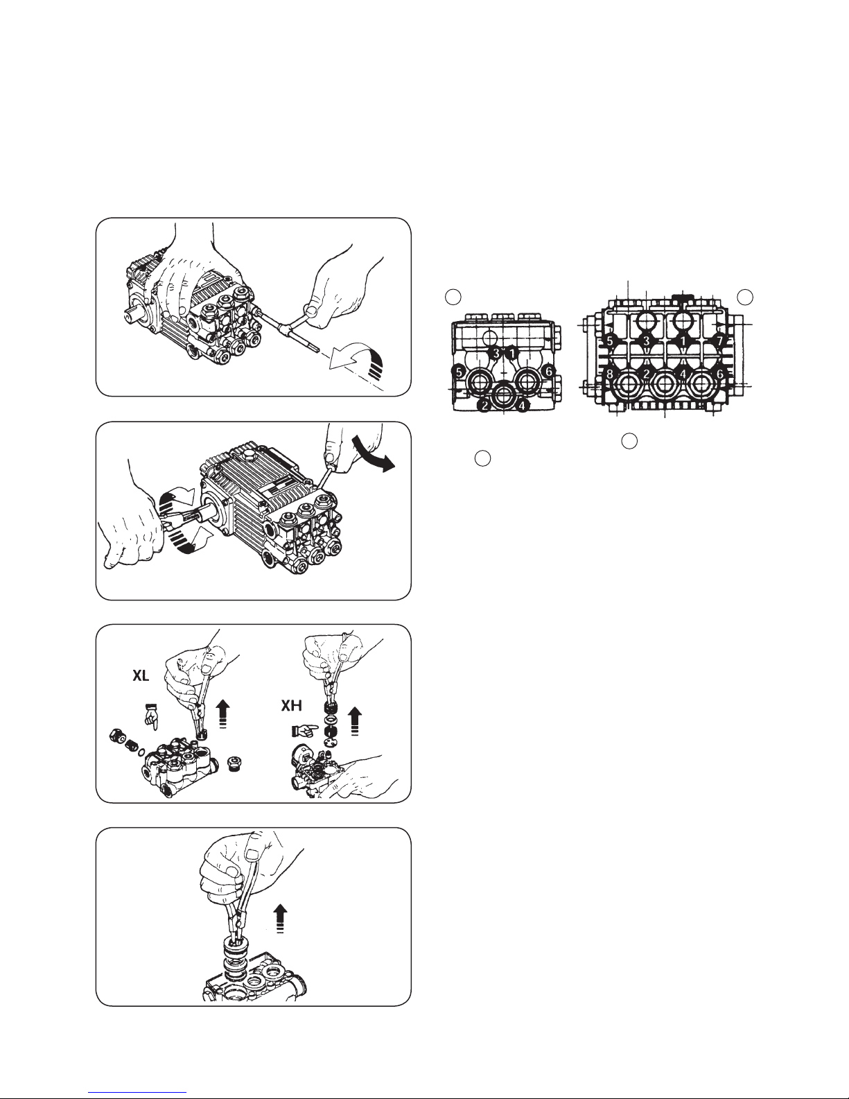
∂Assembly - DisAssembly OfThe PumP heAD
1.1 - Unscrew head bolts.
Tightening sequence of head bolts, for XT Series and HPE
Series, for XR Series and XL Series.
1.2 - Remove the head by rotating the shaft and levering
between head and body.
1.3 - For re-assembly: Invert above instructions, and keep
to torque rates shown on page 8.
insPecTiOn inleT/OuTleT vAlves
2.1 - Remove valve caps, slide out inlet/outlet valves
check the sondition of the various components of the
valve and well as the O-Ring, replace if necessary.
2.2 - For re-assembly: Invert previous operation.
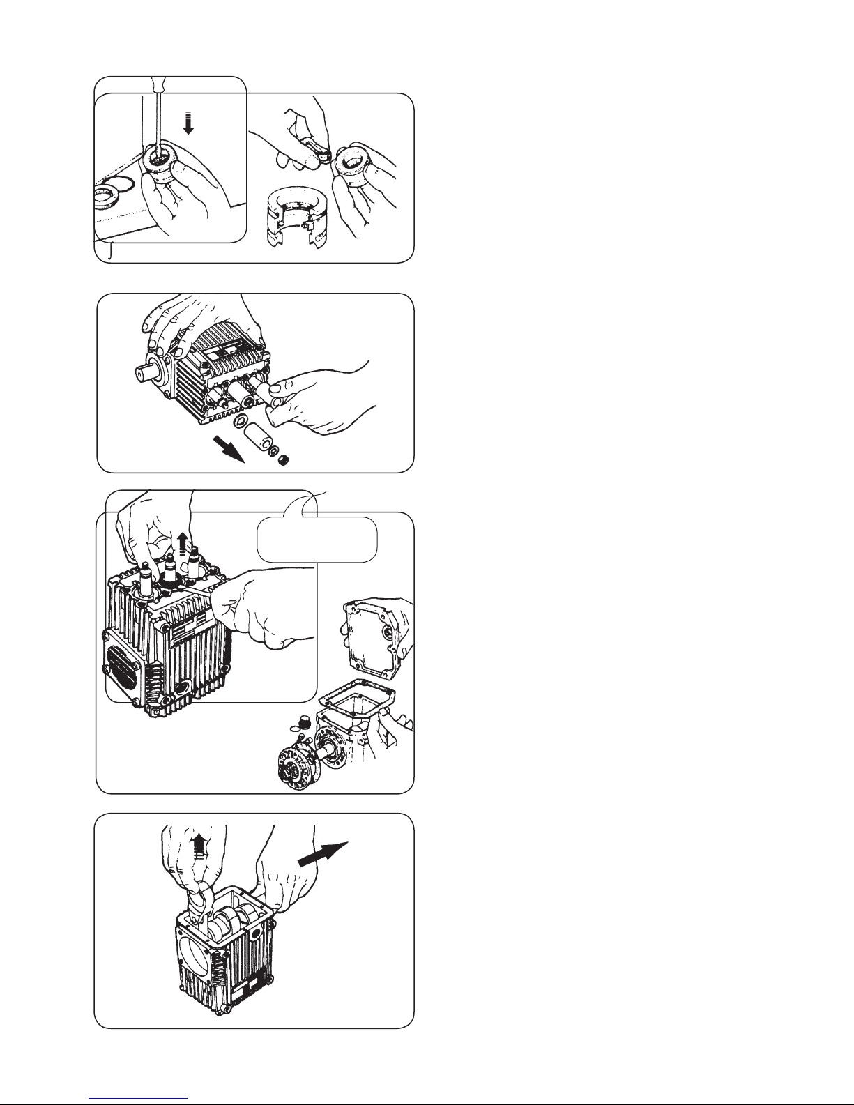
RePlAcing PAcking AnD RecOveRy seAls
3.1 - Remove the head (See ∂), then slide out piston
guides, being careful not the deform them, using the
special extractor pliers.
HIGH PRESSURE PUMP REPAIR INSTRUCTION
ECHO TEC PUMP SERIES
XL-60/2.3, XL-60/3.0 AND XL-60/3.6
∂
AB
B
A
3.2 - Disassemble the components of the piston guide,
checking the condition, replace if necessary.
3.3 - For re-assembly: Invert operation.
RePlAcing The PisTOns
4.1 - Remove the head (See ∂), then unscrew the piston
retainers.
4.2 - Slide off the ceramic pstions, check their condition,
and replace if necessary.
4.3 - For re-asembly: Invert above operations. Keep to
torque rating and shown on page 8.
RePlAcing Oil seAls
6.1 - Remove the head (See ∂),
remove the ceramic pistons
discharge oil
6.2 - Remove the oil seals and the O-Rings, checking the
seats and the piston guides.
6.3 - Remove the rear cover gasket.
6.4 - For re-assembly: Invert above operations. Keep to
torque ratings as shown on page 8.
cRAnk mechAism mAinTenAnce
7.1 - Remove the head (See ∂),
remove the ceramic pistons
discharge oil
7.2 - Remove the rear cover.
7.3 - Remove the con-rod sliding the one piece-rod
whilst removing the shaft.
7.4 - For re-assembly: Invert above operations. Replace
the oil seals!
•
•
•
•
Be careful not to
scratch piston
guide!

ECHO TEC. WATERMAKER LIMITED WARRANTY
Echo Marine Ltd. warrants to the original purchaser for a period of twelve (12) months from the date of
shipment that the ECHO ec. watermaker will perform according to specifications. Echo Marine’s
liability under this warranty shall be limited to repair or replacement of the ECHO ec. watermaker at
Echo Marine’s option. Under no circumstances shall Echo Marine Ltd. be liable for consequential
damages arising out of or in any way connected with the failure of the system to perform as set forth
herein. his limited warranty is in lieu of all other expressed or implied warranties, including those of
merchantability and fitness for a particular purpose.
In the event of a defect, malfunction, or failure during the warranty period, Echo Marine Ltd. will repair
or replace, at its option, the product or component therein which, upon examination by Echo Marine,
shall appear to be defective, or not up to factory specifications.
o obtain warranty service, the defective product or part must be returned to Echo Marine’s Service
Center. he purchaser must pay any transportation or labor expenses incurred in removing and returning
the product to the service center.
he limited warranty does not extend to any system component which has been subjected to misuse,
neglect, accident, improper customer installation, or used in violation of instructions furnished by Echo
Marine Ltd. he warranty does not extend to components on which the serial number has been removed,
defaced or changed.
Echo Marine Ltd. reserves the right to make changes or improvements in its product during subsequent
production without incurring the obligation to install such changes or improvements on previously
manufactured equipment.
he implied warranties, which the law imposes on the sale of this product, are expressly LIMI ED, in
duration to the time period above. Echo Marine shall not be liable for damages, consequential or
otherwise, resulting from the use and operation of this product or from the breach of this LIMI ED
WARRAN Y.
his limited warranty service does not apply to normal recurring user maintenance as described below.
Pre-filter Cartridges Pump Valve Assemblies
Pump Seals Gauge Instrument Calibration
Pump Packings Pump Crankcase Oil

he ECHO ec. Membrane Element is guaranteed to be cleanable for a minimum of one year from date
of shipment, or commissioning of the system by Echo Marine Ltd, provided that cleaning instructions are
adhered to and foulant is acid soluble metal hydroxides and calcium carbonates or alkaline soluble
organic, inorganic substances and microbiological slimes. he ECHO ec. Membrane Element is not
guaranteed against iron fouling (rust), chemical attack, extreme temperatures (over 113º F/under 33ºF),
drying out, or extreme pressures (over 1000 psig).
CAU ION: Use of parts not supplied directly by Echo Marine (generic parts), including but not limited
to maintenance parts, pre-filter elements, cleaning and storage chemicals, pump oil, spare parts,
replacement parts, system components and or system accessories, shall void all warranties expressed or
implied.
ECHO MARINE LTD.
1st Avenue South,
Chaguara as
Trinidad W.I.
TELEPHONE: 1-868-634-2027
FAX: 1-868-634-2026
E-MAIL: echotec@echo- arine.co
www.water akers.net
This manual suits for next models
2
Table of contents
Other ECH2O Tec. Water Filtration System manuals


Popular Water Filtration System manuals by other brands


Theralux
Theralux THERACLEAR 255 Technical description and installation instructions

WaterSoft
WaterSoft SIDEWINDR SW10 Installation & operation manual

Tetra
Tetra Whisper 10-30 manual

Viqua
Viqua PRO24-186/2 owner's manual

Contech
Contech CatchBasin StormFilter Operation and maintenance

Miller-Leaman
Miller-Leaman TGSS-20C owner's manual


