Echelon ROW User manual

SERVICE MA N U A L
R OW

Parts list
1
2
3
567
89
13
4
10
14
11
12
INCLUDES
1. Echelon®Row Base
2. Echelon®Row Rail
3. Rear Foot
4. Front Foot
5. M8*16 screws
6. M10*25 screws
with washer
7. M8*16 screw with
washer
8. M8*20 screw with
washer
9. Hex Key
10. Left Foot Carriage
11. Right Foot
Carriage
12. Seat
13. Adaptor
14. Bracket
QUICK START GUIDE
ACCOUNT CREATION
Go to member.echelonfit.com and follow the on-
screen instructions to choose a plan and setup your
account. This info will be needed to login to your
account on the Echelon Fit App.
All account info and plans are managed at member.echelonfit.
com and use the same login. After creating your account login
on member.echelonfit.com, write down your login info. This will
be the same login for the App.
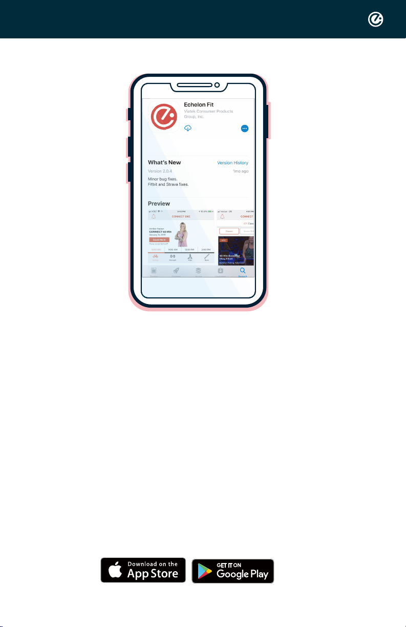
DOWNLOAD THE ECHELON FIT APP
Ensure latest version of the Echelon Fit™ App is
installed from the Google Play Store or the App Store.
OPERATIONAL INSTRUCTIONS
Connect to the Echelon Fit app to accesstutorials
and operation instructions.
ASSEMBLY
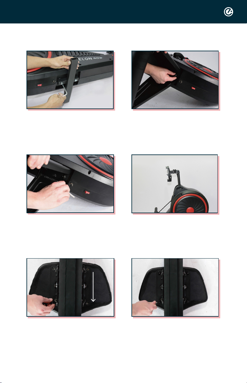
Step1. Remove the bracket (No.14)
and bolt with hex key.
Step 2. Place the front foot and
hand tighten screws (No. 6)into
place.
Step 3. Tighten the screws with
hex key.
Step 4. Set rower upright and
adjust the arm of phone holder to
your desired level.
Step 6. Place all four screws (No.7)
into screw holes and tighten with
hex key.
Step 5. Place seat on ground and
lay the railonto seat so the screw
holes on the bracket align with
screwholes on seat.
*Arrow pointing towards side with handle.
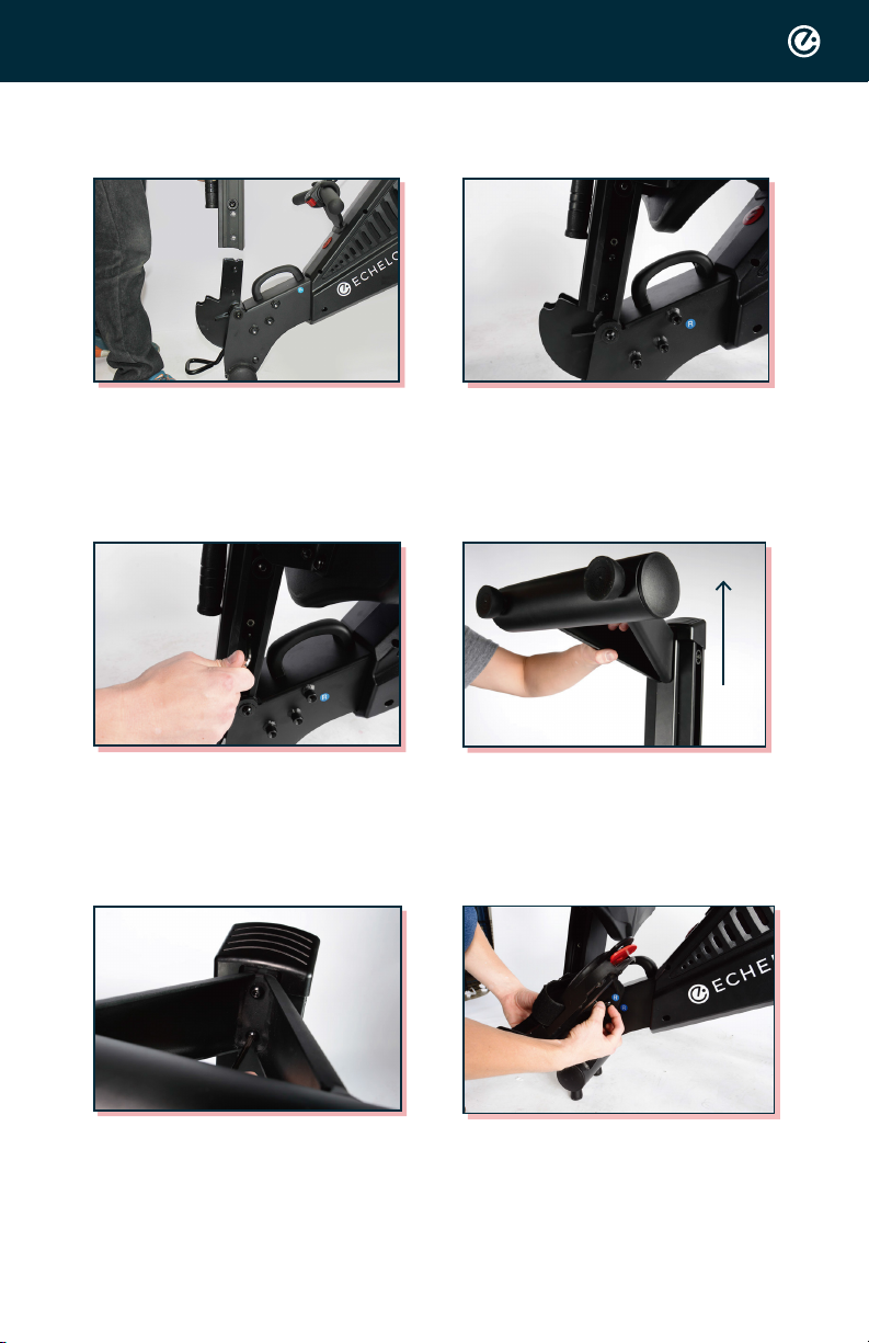
Step 8. Place the four screws
(No.5) into rail and hand tighten.
Step 7. Place the rail onto rail
bracket.
Step 9. Tighten screws with hex
key.
Step 11. Tighten screws with hex
key.
Step 10. Align front foot with
screw holeson the rail and hand
tighten screws (No.8) into the
foot.
ANGLE AWAY
FROM ROW
Step 12. Align the right foot
carriage with the screw holes on
the body of the rower and hand
tighten the three screws.
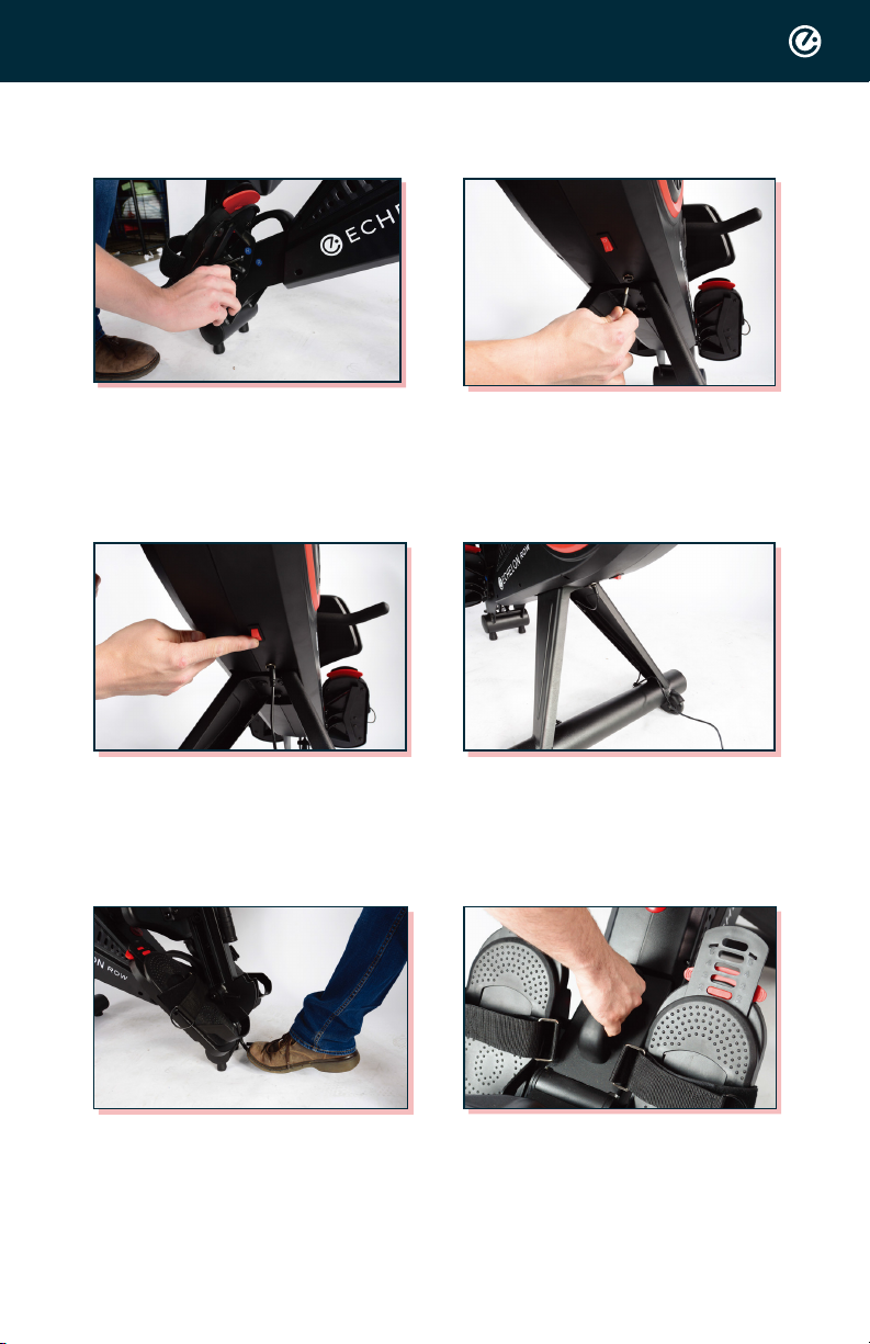
Step13. Tighten screws with hex
key. Repeat with left foot
carriage.
Step 14. Connect the power cord.
Step 15. Toggle the power switch, as
shown above.
Step 16. Route the power cable
through the cable routing
clips legs, as shown above.
Step 17. To lower the rail, press
down the foot pedal at the joint
and lower the rail gently to the
ground.
Step 18. To lock into place, pull up on
this handle until you hear a
click. Once you hear the click,
the rower is safe to use.
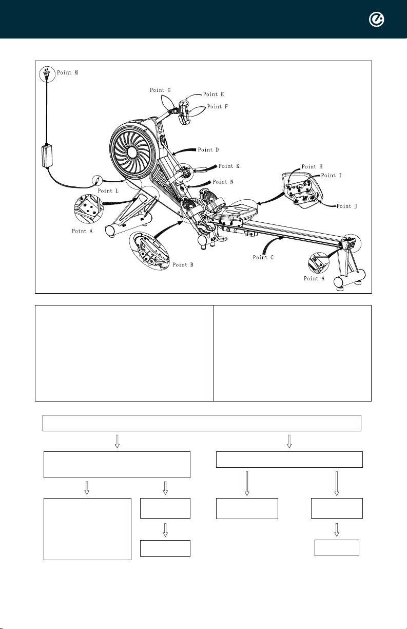
Diagnostic procedures for noise
Point A Screws of front and rear
tube
Point B Screws of foot rest
Point C Monorail
Point D Mesh belt
Point E Adjusting frame of
phone holder
Point F Phone holder lock slot
Point G Axle of phone holder arm
Point H Screw
Point I Adjusting screw
Point J Wheels
Point K Tension controller
Point M Plug in power socket
Point N Bluetooth light
Point L Plug with rowing
machine
•Step 1: Check if bolts on front / rear tube (Point A) are tight enough.
Yes
Yes Yes
No
No No
Step 2: Check if bolts on pedals
(Point B) are tight enough.
No noise
after screwed
Case Closed
Use tools to tighten up
Still have sounds
Check step 2
No noise
after screwed
Case Closed
Need to be evaluated
case by case.
Please provide
1. Product (Bluetooth)
Serial number
2. Video and photo for
further study

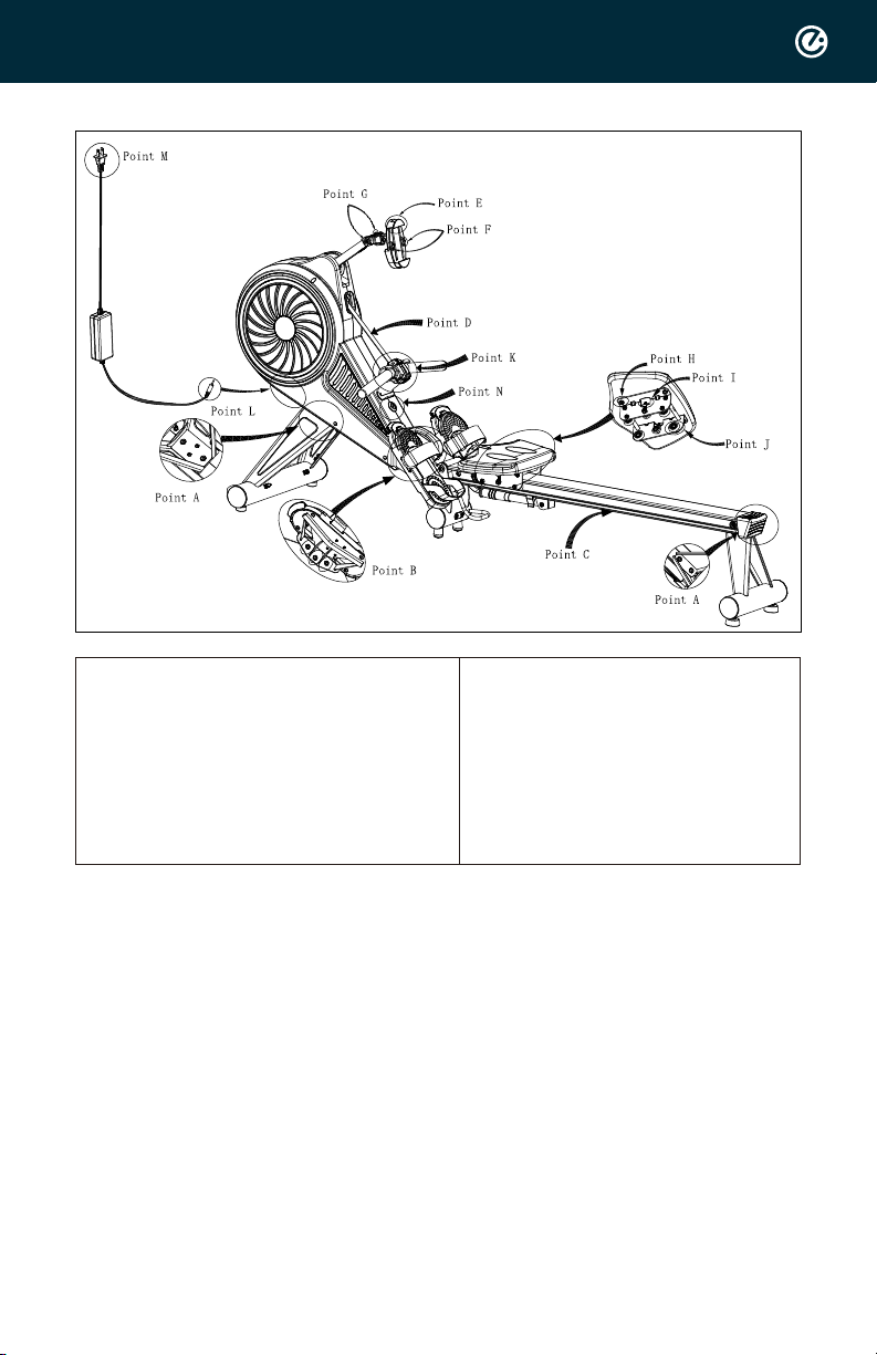
Diagnostic procedures for power on
Point A Screws of front and rear
tube
Point B Screws of foot rest
Point C Monorail
Point D Mesh belt
Point E Adjusting frame of
phone holder
Point F Phone holder lock slot
Point G Axle of phone holder arm
Point H Screw
Point I Adjusting screw
Point J Wheels
Point K Tension controller
Point M Plug in power socket
Point N Bluetooth light
Point L Plug with rowing
machine
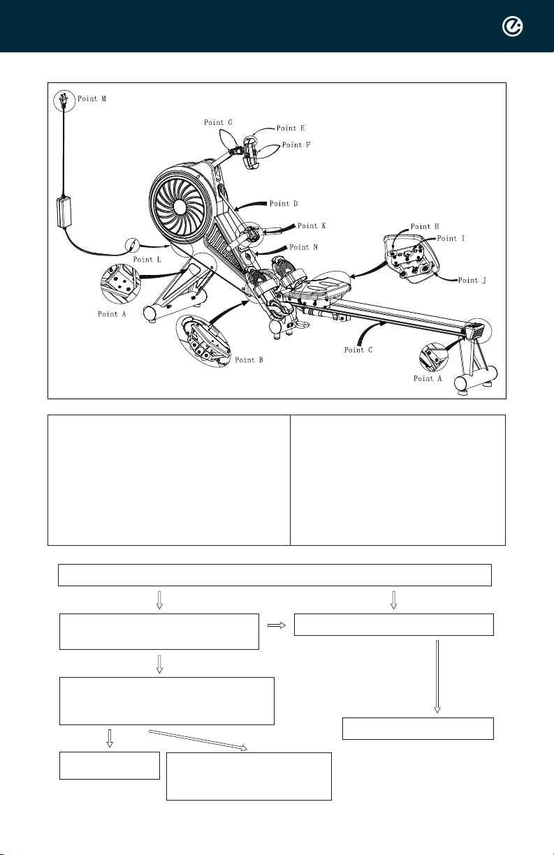
•Step 1: Check if M & L are connected properly, and power switch on as figure shown.
Power on
Case Closed
Still not power on Power on
Case Closed
Need to be evaluated case by
case.
Please provide
1. Product (Bluetooth) Serial
number
2. Video and photo for further
study.
Step 2:
Swap to another power socket, and
check again as last step 1.
Reconfirm if M & L are properly
connected the power switch is turned
on as figure shown .
Hearing a beep sound from Tension
controller (Point K) indicates the
power is on. The Bluetooth light (Point
N) starts flashing.
Still not power on
Yes
Yes No

Yes
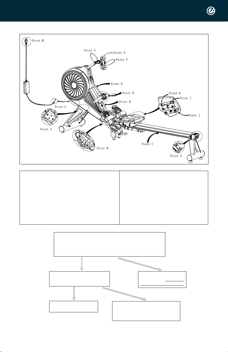
Diagnostic procedures for CONNECTION with APP
Point A Screws of front and rear
tube
Point B Screws of foot rest
Point C Monorail
Point D Mesh belt
Point E Adjusting frame of
phone holder
Point F Phone holder lock slot
Point G Axle of phone holder arm
Point H Screw
Point I Adjusting screw
Point J Wheels
Point K Tension controller
Point M Plug in power socket
Point N Bluetooth light
Point L Plug with rowing
machine
•Step 1: Make sure Rowing machine is power on.
Connect to the
internet and
retest.
Power on Case
Closed
Still not power on
Please check Diagnostic
procedures for power on
Need to be evaluated case by case.
Please provide
1. Product (Bluetooth) Serial number
2. Video and photo for further study.
Step 2:
Make sure the cellular data is on and stable.
The mobile phone is near machine within 2
meter.
Reconnect the power plug and make sure
the socket is functionable.
Step 3:
Make sure the bluetooth of
mobile phone is switch on.
Yes No
No

Diagnostic procedures for tension adjustment.
Point A Screws of front and rear
tube
Point B Screws of foot rest
Point C Monorail
Point D Mesh belt
Point E Adjusting frame of
phone holder
Point F Phone holder lock slot
Point G Axle of phone holder arm
Point H Screw
Point I Adjusting screw
Point J Wheels
Point K Tension controller
Point M Plug in power socket
Point N Bluetooth light
Point L Plug with rowing
machine
•Step 1: Make sure Rowing machine is power on.
Tension adjustable.
Case Closed
Tension adjustable.
Case Closed
Need to be evaluated case by case.
Please provide
1. Product (Bluetooth) Serial number
2. Video and photo for further study.
Re-pair the Tension
controller (Point K) with
ECH-ROW.
Bluetooth lignt on
without flashing.
Step 2:
Check Tension Controller (K) is paired with
ECH-ROW.
Reconnect the power plug and make sure
the socket is functionable.
Step 3:
Check the battery capacity of Tension
controller (Point K) on APP. (Low
battery alert.)
PS. Tension controller (Point K) beeps
while adjusting the tension.
Yes
Yes
Battery capacity is good.
No
No
Diagnostic procedures for Seat
Point A Screws of front and rear
ube
Point B Screws of foot rest
Point C Monorail
Point D Mesh belt
Point E Adjusting frame of
phone holder
Point F Phone holder lock slot
Point G Axle of phone holder arm
•Step 1: Check no obstacles on rail. (point C)
Use clean rag to clean the rail. Wipe the rail with a clean cloth.
•Step 2: Check the seat screws (POINT I)
If too tight, loosen it a bit to work smoothly.
If too loosen, tight it a bit to work smoothly.
•Step 3: Check the seat screws (POINT H)
If too tight, loosen it a bit to work smoothly.
If too loosen, tight it a bit to work smoothly.
•Step 4: Check the wheel (point J) stability and the appearance condition.
1. Can't move seat - check Step 1 --> 2
2. The seat is unstable- check Step 1 --> 3 --> 2
3. It is not smooth while rowing. check Step 3 --> 4
if above can't solve the problemNeed to be evaluated case by case.
Please provide Product (Bluetooth) Serial number & Video and photo for further
study.
Point H Screw
Point I Adjusting screw
Point J Wheels
Point K Tension controller
Point M Plug in power socket
Point N Bluetooth light
Point L Plug with rowing
machine

Diagnostic procedures for power on
Point A Screws of front and rear
tube
Point B Screws of foot rest
Point C Monorail
Point D Mesh belt
Point E Adjusting frame of
phone holder
Point F Phone holder lock slot
Point G Axle of phone holder arm
Point H Screw
Point I Adjusting screw
Point J Wheels
Point K Tension controller
Point M Plug in power socket
Point N Bluetooth light
Point L Plug with rowing
machine
•Step 1: Check if M & L are connected properly, and power switch on as figure shown.
Pull out the handle bar and Check whether the Mesh belt (Point D) remains elastic.
Yes
Need to be evaluated case by case.
Please provide
1. Product (Bluetooth) Serial number
2. Video and photo for further study.
3. Total workout amount.
Yes
Diagnostic procedures: phone holder cannot be CLAMPED, MOVED and fixed.
Point A Screws of front and rear
tube
Point B Screws of foot rest
Point C Monorail
Point D Mesh belt
Point E Adjusting frame of
phone holder
Point F Phone holder lock slot
Point G Axle of phone holder arm
Point H Screw
Point I Adjusting screw
Point J Wheels
Point K Tension controller
Point M Plug in power socket
Point N Bluetooth light
Point L Plug with rowing
machine
•Step 1: Check the phone holder extension condition. (Point E)
Condition good.
Condition good.
Step 2:
Check the phone holder middle plastic
clamp condition. (Point F))
Damage , or out of the clamp funciton.
Please replace new phone holder.
Step 3:
Check the support tube axle condition. (point G)
If too tight, loosen it a bit to work smoothly.
If too loosen, tight it a bit to work smoothly.
Need to be evaluated case by case.
Please provide
1. Product (Bluetooth) Serial number
2. Video and photo for further study.
Movement smoothly.
Case Closed.
other issue.
Diagnostic procedures for APP Data
Point A Screws of front and rear
tube
Point B Screws of foot rest
Point C Monorail
Point D Mesh belt
Point E Adjusting frame of
phone holder
Point F Phone holder lock slot
Point G Axle of phone holder arm
Point H Screw
Point I Adjusting screw
Point J Wheels
Point K Tension controller
Point M Plug in power socket
Point N Bluetooth light
Point L Plug with rowing
machine
Yes
•Step 1:
Make sure ECH-ROW is power on.
Tension controller (Point K) is paried with ECH-ROW.
ECH-ROW connects APP well.
Step 2:
Adjust the tension up and down
by Tension controller (Point K).
Need to be evaluated case by case.
Please provide
1. Product (Bluetooth) Serial number
2. Video and photo for further study.
No
Data still no changed.
The data on APP changed
Case Closed.
Still not power on
Please check Diagnostic
procedures for power on
TOOLS
Screwdriver
Read below instruction carefully.
Making sure you carefully screw in controller and
do not pull the wire out.
See more information in the instruction manual.
Step 1.
Step 3. Step 4. Step 5.
Flip the handle and place on the holder
Open the old controller
Remove the old handle from webbing (IMPROTANT!)
Remove the old controller Put old controller and
screws aside
WARNING: MUST attach
the webbing on the holder
Step 2.
Step 6. Step 7.
Remove 5PCS of screws
from controller
Replacement of Handlebar
Models: Echelon Row

Replacement of Handlebar
Models: Echelon Row
Step 8.
Step 9. Step 10.
Replace with new handle
Re-assemble the controller
Tighten 5PCS of screws
Place 5PCS of screws
Flip back handle. Handle
replacement Complete
Step 11.

TOOLS
Screwdriver
Read below instruction carefully.
Making sure you carefully screw in controller and
do not pull the wire out.
See more information in the instruction manual.
Step 1.
Step 3. Step 4. Step 5.
Flip the handle and place on the holder
Open the old controller
Place with new controller
Remove the old controller Put old controller and
screws aside
Place 5PCS of screw
Step 2.
Step 6. Step 7.
Remove 5PCS of screws
from controller
Replacement of Controller and RE-Pairing Controller with Row
Models: Echelon Row

Replacement of Controller and RE-Pairing Controller with Row
Models: Echelon Row
Step 8.
Step 9. Step 10.
Tighten 5PCS of screw Flip back and put onto
the holder
Switch off the rower
Put handle back onto the
holder Switch on the rower Controller and rower are
now connected
Step 12. Step 13.Step 11.
Press both tension control
bottons simutaneously for
30 sec to reset RF
After 30 sec, the blue light
in the controller box start
twinkling

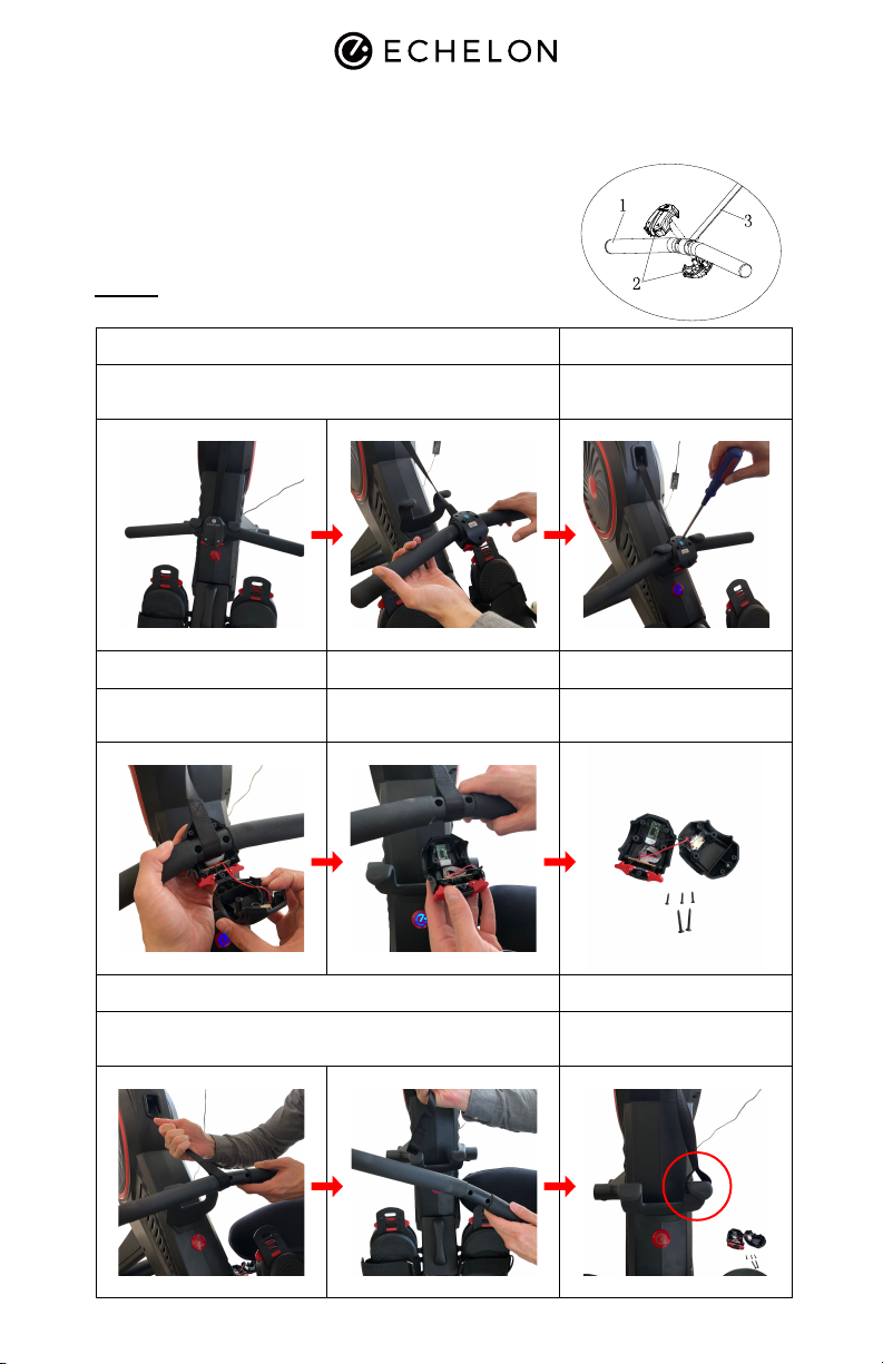
Replacement of Module controller
Models: Echelon Row
TOOLS
Screwdriver
Read below instruction carefully.
See more information in the instruction manual.
Step 1.
Step 3. Step 4.
Remove cable ties
Unscrew the BLT controller
Remove the BLT Controller
Disconnect the cable
Assemble new BLT controller (Tighten screws on
main frame)
Step 2.
Step 5. Step 6.
Unscrew the BLT controller
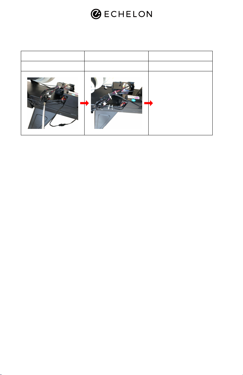
Replacement of Module controller
Models: Echelon Row
Step 7.
Connect cables
Step 8. Step 9.
Tie the cable. Check connection.
1. Plug the power switch
2. Check all connection well.
3. If change the RF controller,
check connection after
replacement
Other manuals for ROW
1
Table of contents


