Synthes Universal Battery Charger II User manual

Universal Battery Charger II. For
Trauma Recon System, Small Battery
Drive and Battery Power Line.
User’s Manual

Introduction
Instructions
Product Information
TableofContents
Universal Battery Charger II 2
Specifications 4
Operating Instructions 6
Power Module Diagnostic Test 9
Small Battery Drive and Battery Power Line 10
Batteries Diagnostic Test
Storing Batteries and Power Modules 12
Care and Maintenance 13
Troubleshooting 14
Technical Data 16
Explanation of Symbols 22
Ordering Information 24
Synthes

Universal Battery Charger II
Application
The Universal Battery Charger II accepts the following
Synthes batteries/power modules to be charged, refreshed
and/or tested:
Small Battery Drive
– 12 V Battery
– 14.4 V Battery
Battery Power Line
– Battery
Trauma Recon System
– Power Module
Safety precautions
– The charger may only be used with the supplied power cord.
– Place the charger on a hard, non-slip, stable base. Ensure
that the ventilation holes in the base of the device are not
covered by towels or other objects.
– Do not cover the side ventilation holes on the device.
– Do not expose the device to direct sunlight or moisture.
– Ensure that liquids cannot seep into the device.
– Do not operate the charger in the direct vicinity of radiators
or other heat emitting devices, as these can affect the device.
– The device may only be used for the authorized Synthes
batteries/power modules.
– Please refer to page 18 for information on the electromag-
netic compatibility.
Important:
– Do not open device. Risk of fatal injury due to electric shock!
– Do not use the device in the sterile area of the operating
room.
– The device may not come into direct or indirect contact
with the patient (see Figure 1 for required clearances).
– Do not wash the device in a washer/disinfector. The device
may not be sterilized. Please refer to page 13 for information
on care and maintenance.
– Do not operate the device in potentially explosive areas.
2Synthes Universal Battery Charger II User‘s Manual
1.5 m1.5 m
1.5 m
2.5 m
Figure 1

Synthes 3
Storage and transport
All batteries/power modules should be removed when
transporting the charger.
Use the original packaging for shipping and transport.
If this is no longer available, please contact your local
Synthes sales consultant.
The same environmental conditions apply for transport
as for storage (see page 12).
Warranty
The warranty for the device is null and void if the device
has not been used properly or the guarantee seal has
been broken. The manufacturer does not accept liability
for damage resulting from repairs or maintenance carried
out by unauthorized sites.

Specifications
4Synthes Universal Battery Charger II User‘s Manual
Universal Battery Charger II
(05.001.204)
The Universal Battery Charger II includes
four independent charging bays. Each
charging bay has three slots for the
following batteries/power module:
– Battery Power Line Battery
– Trauma Recon System Power Module
– Small Battery Drive Battery
Note: The maximum charging time,
depending on the charge status and
type of battery/power module, is 15 to
80 minutes.
Complies with standards:
UL 60601-1, 1st Edition
IEC 60601-1, 2nd Edition
2
3
1
1Battery Power Line Battery (530.620)
2Trauma Recon System Power Module
(05.001.202)
3Small Battery Drive Battery
(532.003 or 532.033)
1Charging bays (4)
2Symbols for battery/power module type
3ON/OFF display
4Control display for each charging bay
5Ventilation holes
6Ventilation holes
7Power switch
8Fuses: 2⳯5AT
9Power cord connection
10PB
Universal Battery Charger II
With respect to electrical shock, fire and
mechanical hazards only in accordance
with UL 60601-1/CAN/CSA C22.2
No. 601.1
IEC 60601-1-2
IEC 60601-1-4
Front view
Rear view
1
2
3
4
6
7
8
9
5

Synthes 5
Subject to technical modifications
Batteries for Small Battery Drive
Part numbers: 532.003/532.033
Operating voltage: 12 V (532.003)
14.4 V (532.033)
Battery capacity: 0.5 Ah
Battery/type: NiCd
Typical charging time: <60 min.
Battery for Battery Power Line
Part number: 530.620
Operating voltage: 14.4 V
Battery capacity: 2 Ah
Battery/type NiMH
Typical charging time: <80 min.
Power Module for Trauma Recon System
Part number: 05.001.202
Operating voltage: 25.2 V
Battery capacity: 1.2 Ah
Battery/type Li-Ion
Typical charging time: <60 min.
Compatible power module/batteries

Operating Instructions
6Synthes Universal Battery Charger II User‘s Manual
Connect the electrical cord to the charger, and plug the cord
into a grounded 110/120 VAC outlet.
Turn on the charger by pressing the “I” on the power switch
(Figure 1).
The ON/OFF display light on the front of the charger will
illuminate (Figure 2).*
Note: If the red caution display light for a single charging
bay illuminates before the power module/battery is inserted,
this charging bay is damaged (Figure 3). The power modules/
batteries can still be charged in the other charging bays, but
it is recommended that the device be sent to the Synthes
Service Department for repair.
Important: Do not operate the charger in the direct vicinity
of radiators or other heat emitting devices, as these can
affect the device.
Place the charger on a hard, non-slip, stable base. Ensure
that the ventilation holes in the base of the device are not
covered by towels or other objects.
Do not expose the device to direct sunlight or moisture.
Do not cover the side ventilation holes on the device.
*If LEDs do not follow this sequence, refer to the troubleshooting section, page 14.
Figure 1
Figure 2
Figure 3

Synthes 7
Insert the power module/battery into one of the appropriate
charging bays. The yellow LED should remain illuminated,
indicating that the battery is charging (Figure 4).*
When the green LED illuminates, the power module/battery
is fully charged (Figure 5).*
Note: The power modules/batteries can be removed during
the charging process; however, they may not be fully
charged and operational time may be shorter.
Important: Always leave the charger switched on when a
power module/battery is inserted in a charging bay.
The battery cells of the power module do not discharge if
not used; however, it is still good practice to check if it is
fully charged prior to use by pressing the information button
and reading the battery charge status display.
Never attempt to insert more than one power module or
battery in the same charging bay.
*If LEDs do not follow this sequence, refer to the troubleshooting section, page 14.
Figure 4
Figure 5

Temperature monitoring
The battery and the charger heat up during the charging
process. Therefore, the ventilation holes should not be covered.
If the temperature is too high, the yellow battery symbol
will flash (Figure 1). To protect the battery, the device stops
charging until the battery has cooled down. If this occurs,
do not remove the battery from the charger until the yellow
battery symbol stays illuminated. The charging time will be
longer in this case.
Charging new batteries or batteries not recently used
New Small Battery Drive or Battery Power Line batteries that
have not been used for longer than 6 weeks and that have
not been stored in an activated charger may require 3 to 5
charging cycles to reach their full capacity. When in doubt,
the charger can be used to check the battery status and to
refresh the battery (see page 10).
Errors during charging
The following errors may occur when charging a battery:
Yellow display light flashes (Figure 1):
The battery is too hot and must cool down before the
charging process can automatically resume. The battery can
be left in the charger.
Red display light illuminates (Figure 2):
The battery is damaged and must be replaced.
No display light:
The battery has not engaged in the charging bay or has
not been recognized by the device. Remove the battery and
insert again or use another charging bay.
Operating Instructions continued
8Synthes Universal Battery Charger II User‘s Manual
Figure 1
Figure 2
flashing

Power Module Diagnostic Test
Synthes 9
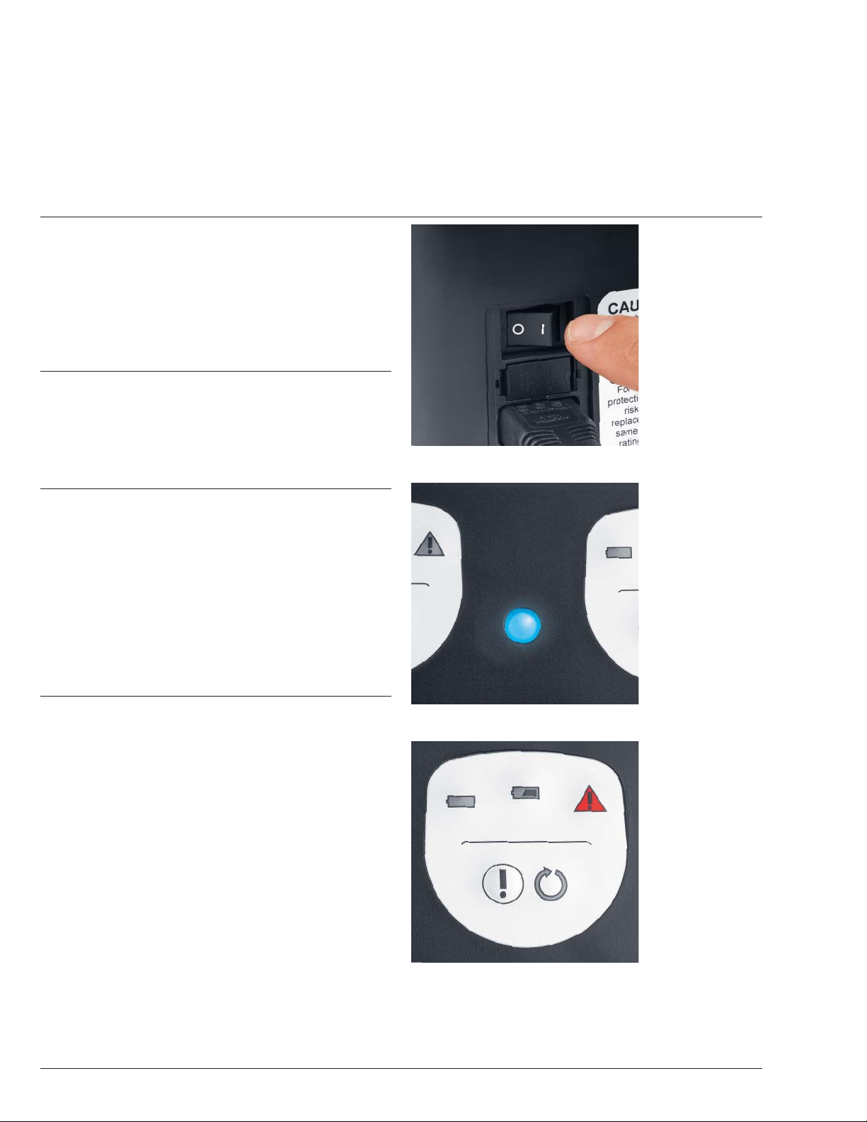
The flashing yellow arrow on the charger display indicates
that it is time for the power module to undergo a diagnostic
test within the next 3 charging cycles (Figure 1).
Note: Please choose a convenient time for the diagnostic
test as it can take up to 4 hours to complete. If the diagnos-
tic test is not initiated within the next 3 charging cycles, the
device will carry out the diagnostic test automatically. The
charger will indicate the need for a diagnostic test when
50 charging cycles have been completed since the last
diagnostic test.
To perform the diagnostic test:
1Insert the power module in an open charging bay.
2Press the exclamation mark button on the charger display
for that charging bay and hold for at least 2 seconds. The
yellow arrow light will turn off, then illuminate while the
diagnostic test is in process.
Diagnosis
Green battery symbol illuminates (Figure 2): Power module
has been tested, charged and is ready to use.
Red caution symbol illuminates (Figure 3): Power module
has been checked, is not charged and cannot be used.
The red service indicator (wrench) on the power module
will also illuminate. Send power module to the Synthes
Service Department.
Notes:
If the power module is inserted in the charger, the service
indicator will remain illuminated. If the power module is
removed from the charger, the service indicator turns off
after a few seconds to save the battery.
Power modules can be charged or undergo diagnostic tests
independently in each charging bay.
Important: Only press the exclamation mark to initiate the
diagnostic test. This test should only be initiated when the
yellow arrow flashes.
Figure 1
Figure 2
Figure 3
flashing

The Small Battery Drive and Battery Power Line batteries can
be tested for remaining capacity or, if they have not been
used for some time, can be refreshed with the Universal
Battery Charger II.
The following can affect battery performance:
– new, unused battery
– battery not used for long period
of time
– old battery
Important: The diagnostic test takes up to 10 hours and
should only be carried out if there is enough time to do so.
After the battery is inserted, the yellow battery symbol
illuminates. To refresh and check the battery, press the
button with the exclamation mark on the charger display
of the charging bay for at least 2 seconds (Figure 1) until
the yellow arrow illuminates (Figure 2). The device then
carries out the diagnostic test. The yellow arrow remains
illuminated throughout the diagnostic process.
Small Battery Drive and Battery Power Line Batteries Diagnostic Test
10 Synthes Universal Battery Charger II User‘s Manual
Figure 1
Figure 2

Synthes 11
Diagnosis
Green battery symbol illuminates (Figure 3): Battery has been
tested, charged and is ready to use. Small Battery Drive
battery is charged with at least 80% capacity remaining and
Battery Power Line battery is charged with at least 70%
capacity remaining.
Red caution symbol illuminates (Figure 4): Battery has been
checked, is not charged and cannot be used. The battery
must be replaced.
Important: The diagnostic test takes up to 10 hours and
should only be carried out if there is enough time to do so.
Note: Batteries can be charged or undergo diagnostic tests
independently in each charging bay.
Important:
– To recharge batteries normally, do not press the exclamation
mark button.
– Checking the battery status and refreshing the battery have
an impact on the battery. If this is carried out frequently,
the lifespan of the battery may be affected.
– Do not remove the battery from the charging bay while
the yellow display is illuminated. Wait until the diagnostic
process has ended and the green or red display illuminates.
Only then is the battery status clearly assessed.
– If the diagnostic process is interrupted, such as a power
outage or a switch to the hospital’s emergency power
system, the diagnostic process must be restarted.
Figure 3
Figure 4

Immediately recharge batteries and the power module after
each use.
Small Battery Drive or Battery Power Line batteries
that are not used should always be stored in a Synthes
Universal Battery Charger II that is plugged in and turned
on (maintenance charge). This guarantees that the
batteries are always fully charged.
It is not necessary to store Trauma Recon System power
modules in the charger. Once charged, they can be stored
outside the charger without any noticeable charge difference.
Note: Do not use batteries/power modules that are not
fully charged. A partial charge may not be sufficient for
the intended use.
Unusable or damaged batteries/power modules should not
be used.
Storing Batteries and Power Modules
12 Synthes Universal Battery Charger II User‘s Manual

Care and Maintenance
Synthes 13
Cleaning
The device must be unplugged before it is cleaned. Occa-
sionally wipe down the device with a dry cloth. If it is very
dirty, the device can be cleaned with a slightly damp cloth.
Dry well. Do not use solvents.
Whenever the charger is cleaned, ensure it is working properly
and is not damaged.
Maintenance of the device is not required.
If there are any damages, please send the device to the Synthes
Service Department.
Important:
– Danger of electric shock! Unplug before cleaning.
– Do not wash the device in a washer/disinfector.
– Do not sterilize the device.
– Make sure that no solution enters the device.
– If necessary, clean the contacts in the charging bays using
extreme care.
Repairs and technical service
The device should be sent to the Synthes Service Department
for repair if:
– the charger is damaged
– the charger malfunctions
– the ON/OFF display does not illuminate when the device is
switched on
– the ON/OFF display flashes when the device is switched on
Users or third parties should not carry out repairs themselves.
Note: The manufacturer shall assume no responsibility for
damage resulting from unauthorized repair.

Problem Possible Causes Remedy
ON/OFF display does not illuminate. Charger is switched off. Turn charger power switch on.
Power cord is not plugged in. Connect power cord to charger,
plug into wall outlet, and switch on.
Power supply is interrupted Check power supply. Replace fuse if
(e.g., damaged fuse). necessary.
Charger is damaged. Send to Synthes Service Department.
ON/OFF display flashes. Charger is damaged. Send to Synthes Service Department.
Power module/battery is inserted Power module/battery is not Ensure the power module/battery is
and charge display status does fully inserted. inserted properly.
not illuminate.
Contacts in the charging bay are dirty. Carefully clean contacts with soft brush.
Power module/battery was not Remove power module/battery and
recognized by the charger. reinsert in an open charging bay.
Power module/battery is damaged. Replace power module/battery.
Charging bay is damaged. Send to Synthes Service Department.
Red caution display Charging bay is damaged. Send to Synthes Service Department.
illuminates when no power
module/battery is inserted.
Yellow battery display flashes Power module/battery is too hot. Leave power module/battery inserted
when charging. in charging bay. Charger automatically
restarts the charging process once the
battery has cooled.
Troubleshooting
14 Synthes Universal Battery Charger II User‘s Manual

Synthes 15
Problem Possible Causes Remedy
Arrow display does not Button was released too soon. Press button and hold for at least
illuminate when exclamation 2 seconds.
button is pressed.
Charging bay is damaged. Send to Synthes Service Department.
Charger has an error. Switch off charger, wait 5 seconds,
and switch charger on. If the ON/OFF
display flashes, send to Synthes Service
Department.
Power module/battery is impossible Power module/battery is being inserted Insert power module/battery into
to insert. into wrong slot in charging bay. correct slot in charging bay.
Contacts in charging bay are bent. Send to Synthes Service Department.
Charger is noisy. Vents on sides, back or base are covered. Position charger so that vents are
exposed.
Charger positioned next to heat source. Position charger away from heat source.
Power module/battery performance Insufficient battery status. Refresh battery (see page 10). Only
is low. possible with Small Battery Drive and
Battery Power Line batteries.
Expected battery life is reached. Test power module/battery (see pages 9
and 10). If the red display illuminates,
replace battery or send power module to
Synthes Service Department for battery
replacement.
Battery is not ready for use. Charge power module/battery until
green display illuminates.
Drive unit or attachment is compromised. Send drive unit or power module to
(i.e. due to insufficient maintenance) Synthes Service Department for repair.
If the suggested solutions are unsuccessful, please contact
the Synthes Service Department at 1 (800) 288-6698.
Synthes recommends an annual preventive maintenance
service by qualified Synthes personnel.

Device specifications
Dimensions (L X W x H) 310 mm X 220 mm X 175 mm
Weight 4.8 kg
Operating voltage 100 VAC–240 VAC,
50 Hz–60 Hz
Operating current 0.8–2.8 A (AC)
Power input rating 250 W
Protection class I, EN 60601-1, paragraph 5.1
Protection type by casing IP X0, EN 60601-1,
paragraph 5.3
Protection degree Type B, EN 60601-1,
paragraph 5.2
Fuse 2 x 5 AT; slow-blow
Operating mode Continuous
Sterilization Device cannot be sterilized
Subject to technical modifications.
Technical Data
16 Synthes Universal Battery Charger II User‘s Manual

Synthes 17
Applicable Standards
The device meets the following standards:
UL 60601-1, 1st Edition
IEC 60601-1, 2nd Edition
CSA C22.2 601.1
Universal Battery Charger II
With respect to electrical shock, fire and mechanical hazards only in
accordance with UL 60601-1/CAN/CSA C22.2 No. 601.1
IEC 60601-1-2
IEC 60601-1-4
Environmental conditions
Operation Transportation and storage
Temperature 40°C 50°C
10°C –20°C
Relative humidity 90% 90%
30% 10%
Atmospheric pressure 1060 hPA 1060 hPA
500 hPA 500 hPA
Important: The device is not suitable for use in the presence
of a flammable anesthetics mixture with air or oxygen, or
with nitrous oxide.

Technical Data continued
18 Synthes Universal Battery Charger II User‘s Manual
Electromagnetic compatibility
Accompanying Documents in Accordance with EN/IEC 60601-1-2, Clause 5.2.2
Table 1: Emissions
Guidelines and manufacturer’s declaration – electromagnetic emissions
The Synthes Universal Battery Charger II is intended for use in the electromagnetic environment specified below. The
customer or the user of the Synthes Universal Battery Charger II should assure that it is used in such an environment.
Emission tests Compliance Electromagnetic environment–
guidance
RF emissions Group 1 The Synthes Universal Battery Charger II
CISPR 11 uses RF energy only for its internal function.
Therefore its RF emission is very low and
it is not likely to cause any interference
in nearby electronic equipment.
RF emissions Class B
CISPR 11
Harmonic emissions Class A
IEC 61000-3-2
Voltage fluctuations/flicker emissions Complies
IEC 61000-3-3
The Synthes Universal Battery Charger II
is suitable for use in all establishments,
excluding domestic establishments and
those directly connected to the public
low-voltage power supply network that
supplies buildings used for domestic
purposes.

Synthes 19
Table 2: Immunity (all devices)
Guidelines and manufacturer’s declaration – electromagnetic immunity
The Synthes Universal Battery Charger II is intended for use in the electromagnetic environment specified below. The
customer or the user of the Synthes Universal Battery Charger II should assure that it is used in such an environment.
Immunity test standard IEC 60601 test level Compliance level Electromagnetic environment–
guidance
Electrostatic discharge (ESD) ±6 kV contact ±8 kV contact Floors should be wood, concrete
IEC 61000-4-2 ±8 kV air ±15 kV air or ceramic tile. If the flooring is a
synthetic material, the relative
humidity should be at least 30%.
Electrical fast transient/burst ±2 kV for power supply ±2kV for power supply Electrical power quality should be
IEC 61000-4-4 lines lines that of a typical commercial or
±1 kV for signal lines ±2kV for signal lines hospital environment.
Surge ±1 kV line to line ±1 kV line to line Electrical power quality should be
IEC 61000-4-5 that of a typical commercial or
±2 kV line to earth ±2 kV line to earth hospital environment.
Voltage dips, short <5% UT<5% UTElectrical power quality should be
interruptions and voltage (0.5 cycle) (0.5 cycle) that of a typical commercial or
variations on power hospital environment. If the user
supply lines 40% UT40% UTof the Synthes Universal Battery
IEC 61000-4-11 (5 cycles) (5 cycles) Charger II requires continued
operation during electrical power
70% UT70% UTinterruptions, it is recommended
(25 cycles) (25 cycles) that the Synthes Universal Battery
Charger II is powered from a UPS.
<5% UTfor 5s <5% UTfor 5s
Note: UTis the AC voltage prior to application of the test level.
Power frequency (50/60 Hz) 3 A/m 30 A/m Power frequency magnetic fields
magnetic field should be at levels characteristic
IEC 61000-4-8 of a typical location in a typical
commercial or hospital environment.
Other manuals for Universal Battery Charger II
4
Table of contents
Other Synthes Batteries Charger manuals