Company name Getac Technology GmbH.
Address Kanzlerstrasse 4
40472 Dusseldorf, Germany
Phone +49 (0) 211-984819-0
Company name Getac UK Ltd.
Address Getac House, Stafford Park 12,
Telford, Shropshire, TF3 3BJ, UK
Phone +44 (0) 1952-207-222
Company name Getac Inc.
Address 15495 Sand Canyon Rd., Suite 350
Irvine, CA 92618 USA
Phone +1-949-681-2900
www.getac.com
Rugged Mobile Computing Solutions
AY-C431
Battery Charger
REFERENCE GUIDE
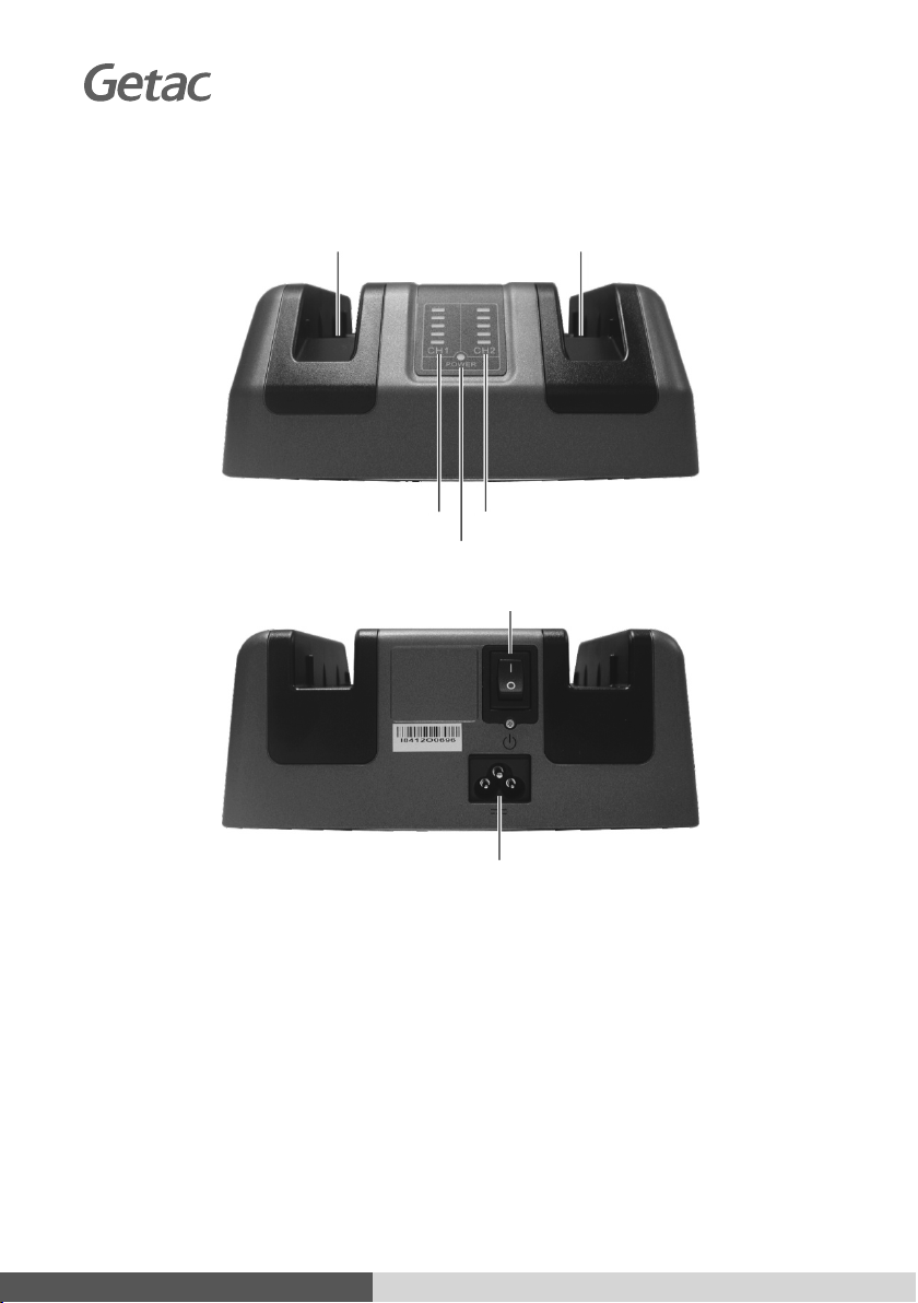
Power Indicator
Bay 2Slot
Bay 1Slot
Bay 1 Charge Indicator Bay 2 Charge Indicator
Power Connector
Power Switch
561581920005 R03
Company name Getac Technology GmbH.
Address Kanzlerstrasse 4
40472 Dusseldorf, Germany
Phone +49 (0) 211-984819-0
Company name Getac UK Ltd.
Address Getac House, Stafford Park 12,
Telford, Shropshire, TF3 3BJ, UK
Phone +44 (0) 1952-207-222
Company name Getac Inc.
Address 15495 Sand Canyon Rd., Suite 350
Irvine, CA 92618 USA
Phone +1-949-681-2900
www.getac.com
Rugged Mobile Computing Solutions
AY-C431
Battery Charger
REFERENCE GUIDE
Power Indicator
Bay 2Slot
Bay 1Slot
Bay 1 Charge Indicator Bay 2 Charge Indicator
Power Connector
Power Switch
561581920005 R03
Reference Guide Reference Guide
Congratulations and thank you for
purchasing the battery charger.
This guide provides operating
information for the charger.
For ITE equipment only
1
.Product Specifications
Items Specifications
Applicable
computer models
A140, B300, B360, F110,
K120, RX10, S410, T800,
UX10, V110, X500
Number of bays 2
Number of LEDs 5 per bay
AC-in power 100 V to 240 V
DC Output 8.4 ~ 17.4 V, 2 ~ 4 A
Charging time Maximum 5 hours
(at 25 °C)
Dimension 160 × 180 × 72.5 mm
Weight 1.22 kg (Max.)
Operating
temperature
5 °C (41 °F) ~ 40 °C (104 °F)
Regulations EMC: BSMI, CCC, CE, FCC
Safety: CB, UL
Green product
coverage
RoHS: 6 European Union
RoHS banned materials
Others: 12 universal GP
product banned materials
2
.Safety Instructions
For optimal performance, use the
charger where the recommended
temperature is between 5 °C (41 °F)
and 40 °C (104 °F).
Avoid placing the charger in a
location subject to high humidity,
extreme temperatures, mechanical
vibration, direct sunlight, or heavy
dust.
Do not cover or block any ventilation
openings on the charger. For example,
do not place the charger on a bed,
sofa, rug, or other similar surface.
Otherwise, overheating may occur
that results in damage to the charger.
Do not place the charger on an
unsteady surface.
To avoid hastening the deterioration
of the battery pack thereby prolonging
its useful life, minimize the number of
times you charge it so as not to
frequently increase its internal
temperature.
The charger will stop charging when
input voltage from the AC power line
is unstable.
Avoid touching the charger bay
terminals or damage may occur,
thereby causing improper operation
to it.
Avoid exposing the charger to water
or an electric shock may occur.
Disconnect the AC power cord from
the charger when not in use. The
charger is still in standby mode even
when charger is powered-off if AC
power is connected.
3
.Inserting Battery Pack(s)
Select Models Only: The main battery
pack of K120 requires installation of a
guide plate. Insert the guide plate to
the right side of the battery slot at an
angle (as shown by and below) and
then push it toward the right to engage
it (as shown by below).
The bay 1 and bay 2 slots of the battery
charger can be for one of the battery
combinations as listed below:
Bay 1 Bay 2 Applicable
Computer Models
Main battery Main battery A140, B300, B360,
F110, K120, RX10,
S410, T800, UX10,
V110, X500
Main battery 2nd battery B300, S410, X500
2nd battery 2nd battery B300, S410, X500
High capacity
battery
High capacity
battery
B360, K120, RX10,
UX10
4
.Connecting Power
1. Plug the female end of the power
cord to the power connector ()
on the charger and the male end
to an electrical outlet ().
2. Press the power button () to
power up and the power indicator
( POWER ) on the front lights
green.
The corresponding bay charge LED
(CH1 / CH2) would light up to indicate
the battery charge level.
Battery Level LED States
Below 20% The first (lowest) bar
blinks.
Above 20% and
below 40%
The first and second bars
blink in turn.
Above 40% and
below 60%
The first, second, and third
bars blink in turn.
Above 60% and
below 80%
The first, second, third,
and fourth bars blink in
turn.
Above 80% and
below 100%
All five bars blink in turn.
100% Only the fifth (highest) bar
glows.
NOTE: The first bar of CH1 LED will
glow in orange if charging is in an
abnormal state.
.
.
.
.
.
.
.
.
.
.
.
.
.
.
.
.
.
.
.
.
.
.
.
.
.
.
.
.
.
.
.
.
.
.
.
.
.
.
.
.
.
.
.
.
.
.
.
.
.
.
.
.
.
.
.
.
.
.
.
.
.
.
.
.
.
.
.
.
.
.
.
.
.
.
.
.
.
.
.
.
.
.
.
.
.
.
.
.
.
.
.
.
.
.
.
.
.
.
.
.
.
.
.
.
.
.
.
.
.
.
.
.
.
.
.
.
.
.
.
.
.
.
.
.
.
.
.
.
.
.
.
.
.
.
.
.
.
.
.
.
.
.
.
.
.
.
.
.
.
.
.
.
.
.
.
.
.
.
.
.
.
.
.
.
.
.
.
.
.
.
.
.
.
.
.
.
.
.
.
.
.
.
.
.
.
.
.
.
.
.
.
.
.
.
.
.
.
.
.
.
.
.
.
.
.
.
.
.
.
.
.
.
.
.
.
.
.
.
.
.
.
.
.
.
.
.
.
.
.
.
.
.
.
.
.
.
.
.
.
.
.
.
.
.
.
.
.
.
.
.
.
.
.
.
Note the orientation and
insert the battery pack to
the matching bay. (Shown
here is one type of the
applicable battery packs.)
CAUTION: When inserting or
removing the battery pack,
be sure to do it in a straight
up or down manner. Never
insert or remove it
in a slanted way
because this can
damage the
connector pins.
S046 561581920005 R03 Press sheet:888*470mm 150LPI(January 8, 2021 13:52:33) 41090 R04
561581920005 R03
41090 R04