Echomaster PBS-MWSK Instruction Manual
Installation/User Manual
Microwave Blind Spot Sensor System
PBS-MWSK

2
Installation Guide
tel - 1-800-477-2267 (East Coast) - 1-888-883-2790 (West Coast)
PBS-MWSK
Microwave Blind Spot Sensor System
Introduction
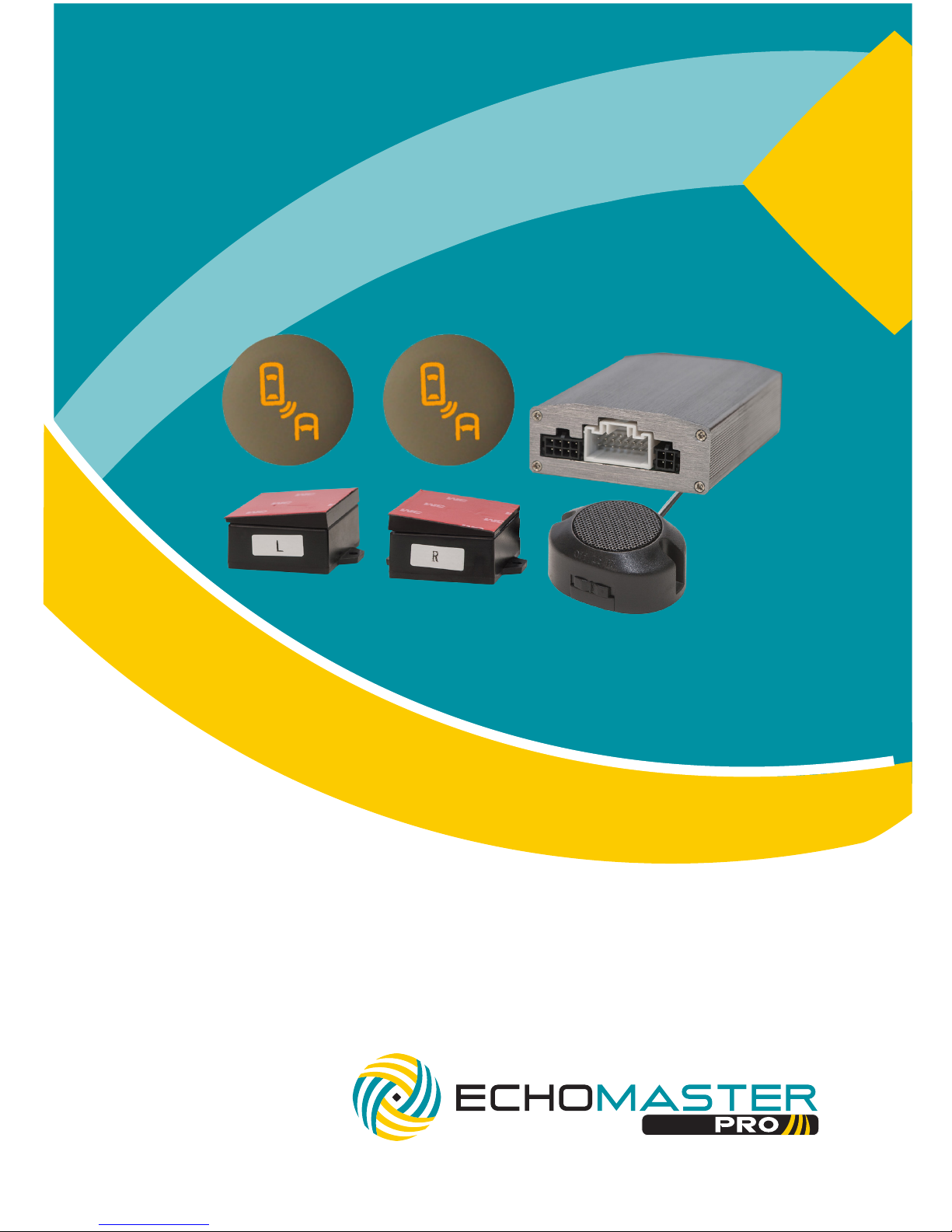
Box Contents Key Features
uAccurate and responsive
microwave sensors
uAudible and visual alerts
uSimple installation, no drilling holes
into the bumper
uUniversal for cars and SUVs
(not to be used with metal bumpers)
uSensor detection range is approx 50ft
uReliable in bad weather
u2 Sensors
u2 LED indicators
uHole Saw
uControl Module
uSpeaker with Volume Control
uPower Harness
uWiring harnesses
uInstall Manual
uWarranty Card
Congratulations on purchasing the EchoMaster Pro Microwave Blind
Spot Sensor system. This detection system is designed for you and
your vehicle’s safety.
EchoMaster® is strictly a driver assistance device, and should not be relied upon as
a substitute for safe driving practices. Use common sense when driving and always
follow recommended safe driving guidelines from your local state and county
Department of Motor Vehicles. To help prevent accidents, always use caution, looking
visually to ensure your path is clear. The owner shall not be entitled to recover from
EchoMaster, its successors or assignees, incidental and consequential damages,
such as personal injury, loss of income, loss of time, loss of prots, loss of vehicle use
or property damage.
No employee, agent or representative of EchoMaster or authorized dealer may modify,
alter or extend this warranty in any way. This warranty gives you specic legal rights.
You may also have other rights under this warranty which may vary from state to state.
Note: Under no circumstances should you attempt to open the control box or any
other component. Doing so will void all manufacturer’s warranties.

3
tel - 1-800-477-2267 (East Coast) - 1-888-883-2790 (West Coast)
Installation Guide
Fitting Instructions
PBS-MWSK
Microwave Blind Spot Sensor System
Installing the Sensors
Remove the bumper and locate where to mount the sensors. The locations should be close to the corners on
the inner rear side and at least 18 in (45 cm) from the ground. Clean the surface prior to mounting the sensors.
Test the sensors before installing them onto the bumper.
Check the labels on top of the sensors and the 3M sticker base to distinguish left
and right sensors. When mounting the sensors, ensure that the wire side is facing downward. Keep the sen-
sors symmetrical on both sides.
Note:
Adhesives can be used when installing the sensor base to the rear bumper, but please use
caution when applying as to not spill adhesive on the surface of the sensor.
After sensors are mounted on the bumper, re-install the bumper. Route the sensor cables into the trunk or rear
passenger compartment utilizing a factory grommet.
Connect to the extension harness and route both extension harnesses to the front
of the vehicle. Connect to main control module.
Wiring for Left Side Harness Routing Wiring for Right Side Harness Routing
RIGHT Turn Signal (Brown)
LEFT Turn Signal (Purple)
Right A-Pillar LED Right
Sensor
Left
Sensor
Left A-Pillar LED
Buzzer
Control Module
ACC (Red)
RIGHT Turn Signal (Purple)
LEFT Turn Signal (Brown)
For right side harness routing connect the turn signal wires the opposite way round to
the left side harness routing.
The short tail on the main harness that connects to the sensor always corresponds to the
brown indicator wire (for example; if the short tail connects to the left sensor the brown wire
will connect to the left indicator and subsequently if the short tail connects to the right sensor
the brown wire will connect to the right indicator).
Microwave sensors should be installed in the inner
side of the rear bumper. Take the rear bumper off
and stick the microwave sensor in the corner of
the rear bumper (close to the rear side).
Please install to the spot at least 45cm height
from the ground.
To Control Module
Short Tail
(Brown Wire)
Sensor Sensor
Long Tail
(Purple Wire)

4
Installation Guide
tel - 1-800-477-2267 (East Coast) - 1-888-883-2790 (West Coast)
Wiring Diagram
Fitting Instructions (continued)
Powering the system
From the main harness, connect the Left Turn trigger wire and the Right Turn trigger
wire to the appropriate turn signal bulbs.
Red wire goes to ACC and black wire goes to Ground (can be found in either of the
kick panels or a 12V outlet) to power the control module.
PBS-MWSK
Microwave Blind Spot Sensor System
Installing the LED indicators and Speaker
Remove A-pillar covers. Find a suitable mounting location where there are no
obstructions behind the pillar panel. Do NOT drill into the pillar cover prior to removing
it and checking for obstructions.
Using the supplied hole saw, drill the hole into the pillar cover. Insert the LED indicator
and ensure that it snaps into place and is in the proper orientation. Connect to the
extensions and route down the A-pillar to the main control module. Re-install the
A-pillar covers.
Mount the speaker under the dash (where still accessible for volume control) and route
the cable to connect to the main harness.
5
tel - 1-800-477-2267 (East Coast) - 1-888-883-2790 (West Coast)
Installation Guide
PBS-MWSK
Microwave Blind Spot Sensor System
Operating Guide
System will become engaged once vehicle is running.
The microwave sensor system will only detect moving objects within the blind spot of
your vehicle. Only when the speed of the moving object is greater than your current
speed, the system will detect and alert the driver.
Once an object is detected, the system will alert the driver via visual alert.
If the turn signal is activated while an object is detected, the system will alert the
driver via visual and audible alert.
Note
Performance may be affected by extreme weather conditions (such as rainstorm and
blizzard).
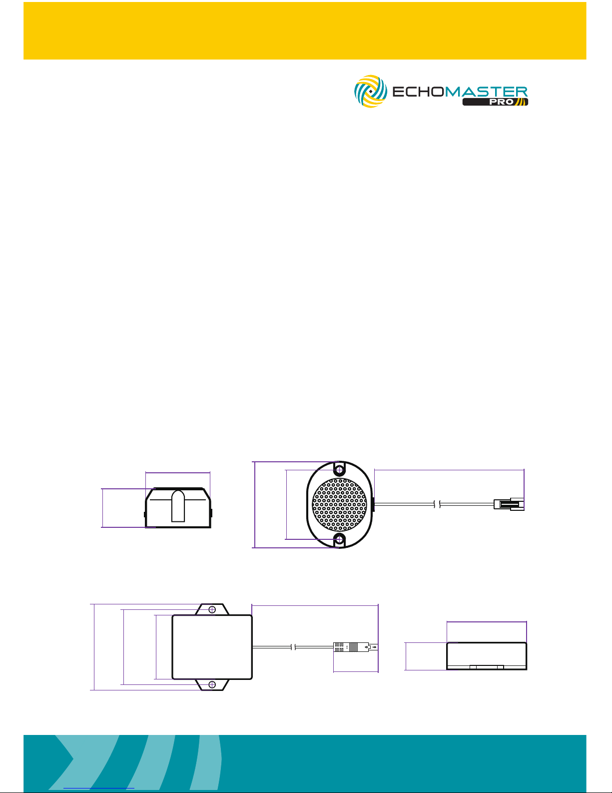
Dimensions (mm/in)
Buzzer
52mm/2"
42mm/1.65"
290mm/11.4"
39mm/15.35"
23mm/0.9"
Microwave Sensors
59mm/2.32"
21mm/0.83"
34.2mm/1.35"
494mm/19.45"
66mm/2.6"
57.4mm/2.26"
49mm/1.93"

6
Installation Guide
tel - 1-800-477-2267 (East Coast) - 1-888-883-2790 (West Coast)
PBS-MWSK
Microwave Blind Spot Sensor System
Dimensions (mm/in)
Control Module
26mm/1.02"
63mm/2.49"
63mm/2.49"
87mm/3.43"
LED Indicator
166mm/6.54"
18mm/0.7"
9.5mm/0.37"

7
tel - 1-800-477-2267 (East Coast) - 1-888-883-2790 (West Coast)
Installation Guide
Specications
PBS-MWSK
Operating Voltage 12V DC
Current Consumption 200mA
Power Consumption 2.4W
Operating Temperature Range -40 - +85C
Detection Range 50ft (15m)
PBS-MWSK
Microwave Blind Spot Sensor System

tel - 1-800-477-2267 (East Coast) - 1-888-883-2790 (West Coast)
tel - +44(0)1420 487110 (sales) - +44(0)1420 470618 (technical)
15500 Lightwave Drive, Suite 202, Clearwater, Florida 33760
Woolmer Way, Bordon, Hampshire, United Kingdom
EchoMaster is a Power Brand of AAMP Global.
EchoMaster.com REV. 121516
Table of contents
Popular Accessories manuals by other brands
 installation guide")
Altai Technologies
Altai Technologies A8n (ac) installation guide

Champion
Champion Flightmaster Jr. Owner's instruction manual

DANA
DANA 4900-3 parts list

Ectosense
Ectosense NightOwl Healthcare Professional Manual

Baumer
Baumer GIM700DR manual

La Crosse Technology
La Crosse Technology TX8U instruction manual


