Nora Lighting NE-901LED User manual
®
®
®
®
6505 Gayhart St., Commerce, CA 90040 | Phone: 800.686.6672 | FAX: 800.500.9955 www.noralighting.com | e-mail: [email protected]
Specifications subject to change without notice. © 2017
IMPORTANT SAFEGUARDS:
READ AND FOLLOW ALL SAFETY INSTRUCTIONS
1. Review the diagrams thoroughly before beginning.
2. All electrical connections must be in accordance with local codes, ordinances and the National Electric code.
3. Disconnect power at fuse or circuit breaker before installing or servicieng.
4. Do not use outdoors.
5. Do not mount in hazardous locations, or near gas or electric heaters.
6. Do not let power cords touch hot surface.
7. Equipment should be mounted in locations and at heights where it will not be subjected to tampering by unauthorized personnel.
8. The use of accessory equipment not recommended by the manufacturer may cause an unsafe condition.
9. Do not use this equipment for other than intended use.
10. All servicing should be performed by a qualified personnel only.
11. Allow battery to charge for 24 hours before first use, for 2-battery models, need 48 hours to fully charge batteries.
LED MODULE REPLACEMENT
LED Module with 11W high perpormance power LED. If needed, please contact the factory.
FUNCTION:
1. For normal lighting use, the fixture can be configured for automatic operation by the built in daylight photo sensor, or can be switched
through an external switch. For battery backup models the fixture will illuminate from the battery power on loss of normal AC,
regardless of the photo sensor or wall switch operation.
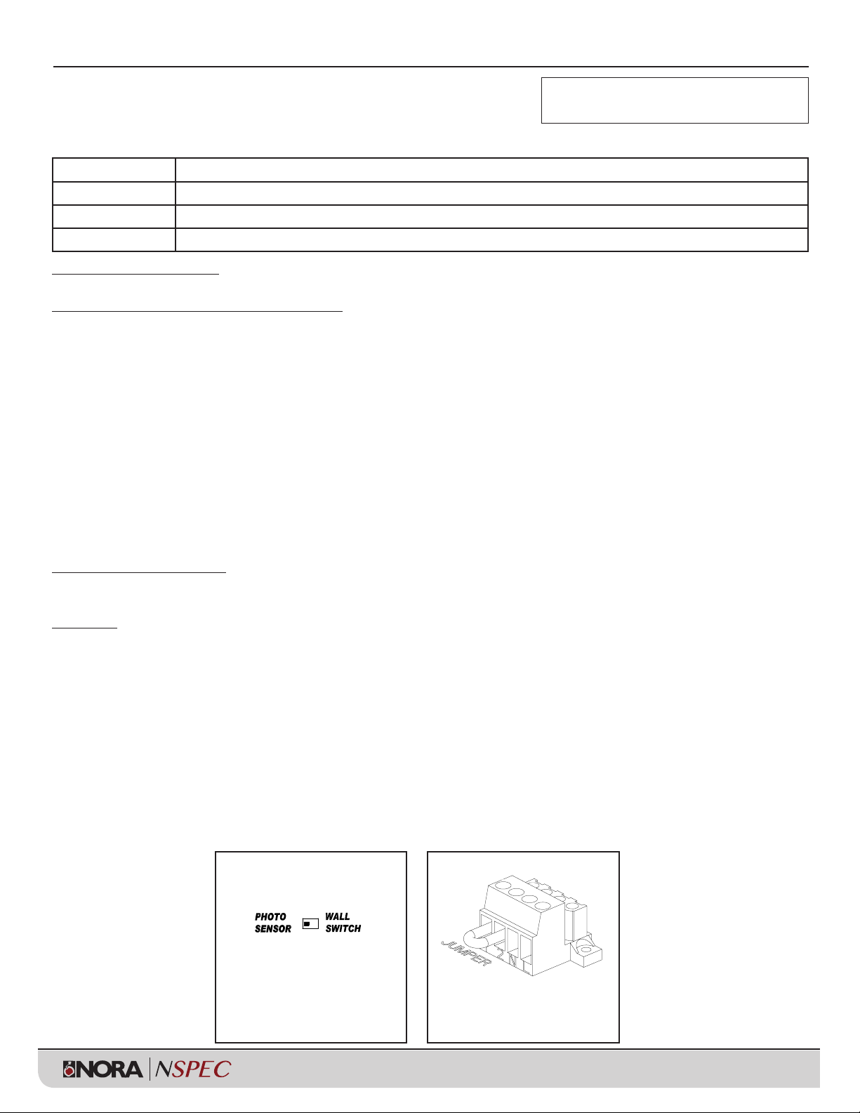
2. For photo sensor operation, leave the jumper between terminals 1 and 2 and slide the slide switch to the Photo Sensor position
(see Fig. 4 for wiring connections). The photo sensor will turn the fixture on when the ambient lighting < 10 Lux,
and off when the ambient lighting > 30 Lux.
3. For an external switch: remove the jumper between terminals 1 and 2, connect the switch device between terminals 1 and 2, and
slide the slide switch to the Wall Switch position (see Fig. 5 for wiring connections). The external switch connections must be fully
isolated from any other circuitry.
4. For “Normally Off” standby battery backup operation only: connect the AC power as shown in Fig. 2 or 3 below and remove the
jumper between terminals 1 and 2. The slide switch is defeated in this mode so it can be in either the Photo Sensor or Wall Switch
positions.
Slide the switch to select
function
ALWAYS TURN OFF MAIN POWER BEFORE INSTALLATION
INSTALLATION SHOULD BE CARRIED
OUT BY YOUR LOCAL ELECTRICIAN.
Installation Instructions
***URGENT: READ PRIOR TO ATTEMPTING INSTALLATION***
NE-901LED
DECO LED EM LIGHT W/ PHOTO SENSOR, SELF-DIAGNOSTICS,
COLD WEATHER OPTION, 5000K
Item # Description
NE-901LEDWCC DECO LED EMERGENCY LIGHT W/ PHOTO SENSOR, SELF-DIAGNOSTICS, COLD WEATHER OPTION, 5000K, WHITE
NE-901LEDBZCC DECO LED EMERGENCY LIGHT W/ PHOTO SENSOR, SELF-DIAGNOSTICS, COLD WEATHER OPTION, 5000K, BRONZE
NE-901LEDBCC DECO LED EMERGENCY LIGHT W/ PHOTO SENSOR, SELF-DIAGNOSTICS, COLD WEATHER OPTION, 5000K, BLACK
®
®
®
®
6505 Gayhart St., Commerce, CA 90040 | Phone: 800.686.6672 | FAX: 800.500.9955 www.noralighting.com | e-mail: [email protected]
Specifications subject to change without notice. © 2017
Installation
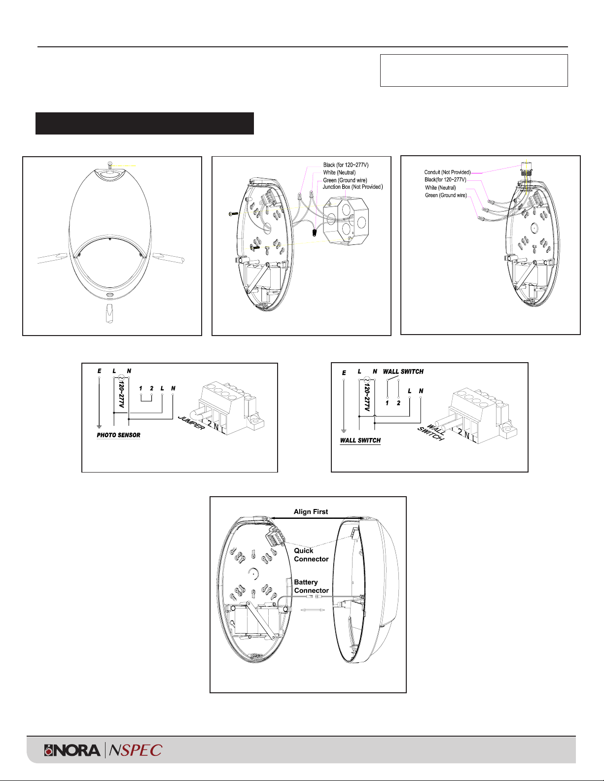
Fig. 1
Open the front cover.
Fig. 3
Installation using conduit.
Fig. 6
Assembly and Quick Connector
Fig. 4
Wiring diagrams for photo sensor.
Fig. 5
Wiring diagrams for wall switch.
Fig. 2
Installation using J-Box
ALWAYS TURN OFF MAIN POWER BEFORE INSTALLATION
INSTALLATION SHOULD BE CARRIED
OUT BY YOUR LOCAL ELECTRICIAN.
Installation Instructions
***URGENT: READ PRIOR TO ATTEMPTING INSTALLATION***
NE-901LED
DECO LED EM LIGHT W/ PHOTO SENSOR, SELF-DIAGNOSTICS,
COLD WEATHER OPTION, 5000K
®
®
®
®
6505 Gayhart St., Commerce, CA 90040 | Phone: 800.686.6672 | FAX: 800.500.9955 www.noralighting.com | e-mail: [email protected]
Specifications subject to change without notice. © 2017
Instructions for Self-Diagnostics / Self-Testing Function
1. Install Emergency Lighting according to the instructions.
2. Once the AC power is supplied to the fixture, the unit will automatically initiate a self-test and self-diagnostic test as follows.
(1) Verifies battery disconnection, charger failure, transformer failure at every 5 seconds.
(2) 1-minute self-testing (battery discharging test) every month.
(3) 30-minute self-testing (battery discharging test) on the 6th month of the year.
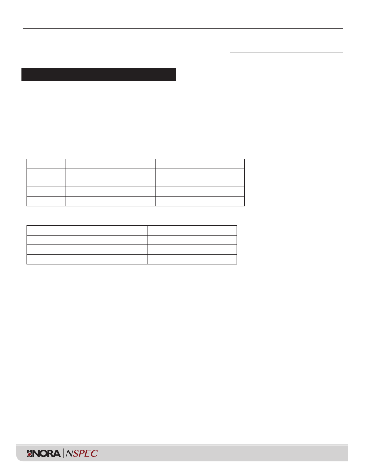
3. Dual color LED lamp shows the following status:
(1) Green color (Operating Status) - ON/READY. Blinking: Testing
(2) Red color (Service Alert)
(3) Service Alert LED Code
4. For manual test, press test button as follows:
IMPORTANT:
After correcting a service alert fault, it is necessary to push the test button for 2 seconds.
Once released, the LED indicator will be green if all faults have been corrected.
•
1 blink ON/pause (4 seconds) Battery is not connected.
••
2 blinks ON/pause (4 seconds) Battery is shorted or battery voltage
drops below an acceptable value.
•••
3 blinks ON/pause (4 seconds) Charger board circuit fault.
••••
4 blinks ON/pause (4 seconds) Transformer fault
Press test button 1 time (within 2 seconds) 1 minute test
Press test button 2 times (within 2 seconds) 5 minutes test
Press test button 3 times (within 2 seconds) 30 minutes test
Press test button 4 times (within 2 seconds)
90 minutes test
ALWAYS TURN OFF MAIN POWER BEFORE INSTALLATION
INSTALLATION SHOULD BE CARRIED
OUT BY YOUR LOCAL ELECTRICIAN.
Installation Instructions
***URGENT: READ PRIOR TO ATTEMPTING INSTALLATION***
NE-901LED
DECO LED EM LIGHT W/ PHOTO SENSOR, SELF-DIAGNOSTICS,
COLD WEATHER OPTION, 5000K
Table of contents
Popular Accessories manuals by other brands

Rice Lake
Rice Lake 1280 Enterprise Series Technical manual

Young Living
Young Living Feather the Owl Operation manual

Argo
Argo ARMONY operating instructions

CONVEY-ALL
CONVEY-ALL 1635-FL Operator's manual

PCB Piezotronics
PCB Piezotronics 208C03 Installation and operating manual

LEGRAND
LEGRAND Wattstopper UT-355 installation instructions

OLAER
OLAER LHC2 Installation and Servicing Manual

STEINEL PROFESSIONAL
STEINEL PROFESSIONAL IS 2360 DE ECO user guide

Sonero
Sonero X-IMS030 user manual

STEINEL PROFESSIONAL
STEINEL PROFESSIONAL IS 3360 MX COM1 Information

NorthStar
NorthStar BR24 - MOUNTING TEMPLATE A4 1-1 Mounting template

Pyxis
Pyxis ST-565 instruction manual


