Velux KLA S105 User manual

VAS 453115-2022-04
ENGLISH: Instructions for wind and rain sensor with power supply
unit and interface
DEUTSCH: Anleitung für Wind- und Regensensor mit
Stromversorgungseinheit und Interface
FRANÇAIS : Notice de anémomètre et détecteur pluie avec unité
d'alimentation électrique et interface
DANSK: Vejledning til vind- og regnsensor med strømforsynings-
enhed og interface
NEDERLANDS: Instructies voor wind- en regensensor met
stroomvoorzieningseenheid en interface
SVENSKA: Anvisning för vind- och regnsensor med
strömförsörjningsenhet och interface
ITALIANO: Istruzioni per sensore vento e pioggia con unità
di alimentazione e interfaccia
KLA S105

2 VELUX®VELUX®3
ENGLISH 3-11
DEUTSCH 12-19
FRANÇAIS 20-27
DANSK 28-35
NEDERLANDS 36-43
SVENSKA 44-51
ITALIANO 52-59

2 VELUX®VELUX®3
ENGLISH 3-11
2 m
KUX 110 KLF 200
KLA S105

4 VELUX®VELUX®5
IMPORTANT INFORMATION
Read instructions carefully before installation and operation. Keep
instructions for future reference and hand them over to any new user.
Safety
• Disconnect mains supply before installation or removal of the sensor
KLA S105 and before carrying out any maintenance or service work
and ensure that it cannot be reconnected unintentionally.
• If the sensor is activated, the chain actuator automatically closes the
modular skylight. For personal safety, never have your hand or body
out of the modular skylight without disconnecting from mains supply.
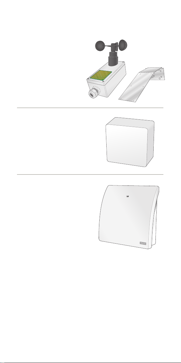
Installation
• The sensor must be installed in accordance with current national
legislation.
• The sensor must be positioned approx 2 m above the roof surface, be
exposed to the elements and if possible close to the modular skylight.
• The sensor must be connected to power supply unit KUX 110 and inter-
face KLF 200, please refer to the instructions for these products.
NB: These products are for indoor installation only.
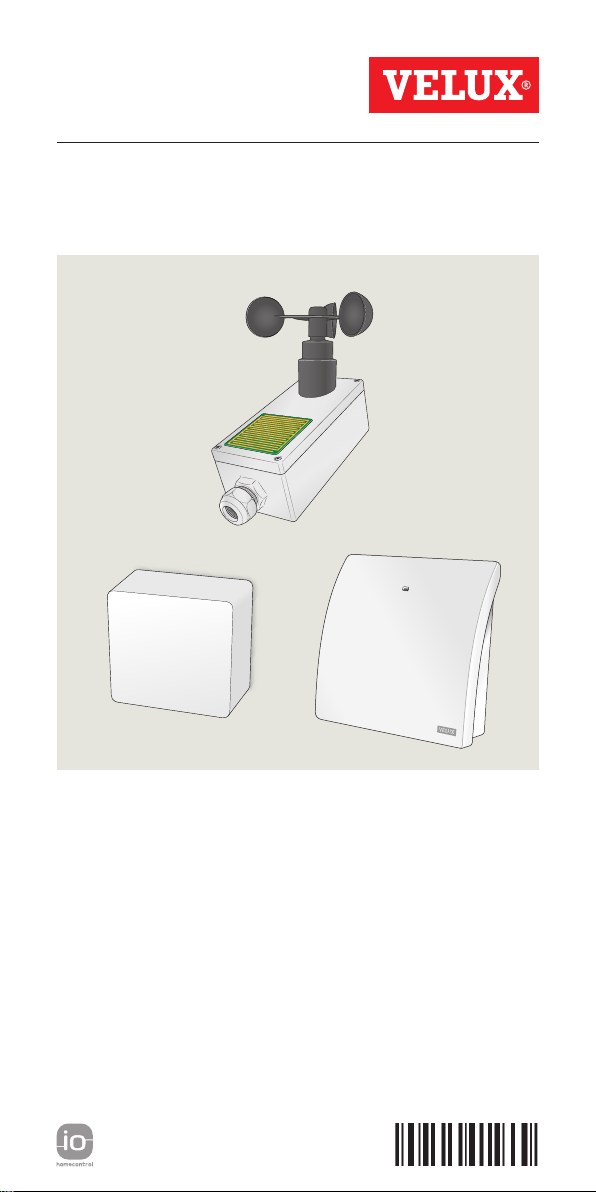
Product
• The sensor has been designed for use with genuine VELUX products.
Connection to other products may cause damage or malfunction.
• The sensor is a low voltage product.
• Do not paint or lacquer the sensor.
• Dirt on the sensor may cause operating problems. Therefore, it is
recommended to clean the sensor with a soft wet cloth once or twice a
year or when required.
• The packaging must be disposed of in accordance with national regula-
tions.
• The product, including batteries if any, is regarded as electrical and
electronic equipment and contains hazardous materials, components
and substances. The crossed out wheeled bin symbolises that electrical
and electronic equipment waste must not be disposed of together
with household waste. It must be collected separately at recycling sta-
tions or other collection sites or retrieved directly from households to
increase the possibilities of recycling, reuse and utilisation of electrical
and electronic equipment waste. By sorting electrical and electronic
equipment waste with this symbol, you contribute to reducing the
volume of incinerated or buried waste and to reducing any negative
impact on human health and the environment. Further information can
be obtained from the local municipality's technical administration or
from your VELUX sales company.
• If you have any technical questions, please contact your VELUX sales
company, see telephone list or www.velux.com.
io-homecontrol®provides advanced and secure radio technology that is easy to install.
io-homecontrol®labelled products communicate with each other, improving comfort,
security and energy savings.
www.io-homecontrol.com

4 VELUX®VELUX®5
DECLARATION OF CONFORMITY
We herewith declare that VELUX wind and rain sensor KLA S105
(BM-RC017)
−is in conformity with the EMC Directive 2014/30/EU and the
RoHS Directive 2011/65/EU,
−has been manufactured in accordance with the harmonised standards
EN 61000-6-1(2007) and
EN 61000-6-3(2007)+A1(2011)+A1/AC(2012) and
−has been assessed in accordance with the harmonised standard
EN 50581(2012).
VELUX A/S: . . . . . . . . . . . . . . . . . . . . . . . . . . . . . . . . . . . . . . . . . . . . . . . . . . . . .. .
(Jens Aksel Thomsen, Advanced Certification Specialist)
Ådalsvej 99, DK-2970 Hørsholm. . . . . . . . . . . . . . . . . . . . . . DoC 940439-00
07.07.2022

6 VELUX®VELUX®7
DECLARATION OF CONFORMITY
We herewith declare that VELUX wind and rain sensor KLA S105
(BM-RC017)
−is in conformity with the Electromagnetic Compatibility Regulations
2016 (S.I. 2016/1091) and the Restriction of the Use of Certain Haz-
ardous Substances in Electrical and Electronic Equipment Regulations
2012 (S.I. 2012/3032),
−has been manufactured in accordance with the UK designated
standards EN 61000-6-1(2007) and
EN 61000-6-3(2007)+A1(2011)+A1/AC(2012) and
−has been assessed in accordance with the UK designated standard
EN 50581(2012).
On behalf of our local representative:
VELUX Company Ltd.
Woodside Way, Glenrothes East, Fife, KY7 4ND
United Kingdom
VELUX A/S: . . . . . . . . . . . . . . . . . . . . . . . . . . . . . . . . . . . . . . . . . . . . . . . . . . . . .
(Jens Aksel Thomsen, Advanced Certification Specialist)
Ådalsvej 99, DK-2970 Hørsholm. . . . . . . . . . . . . . . . . . . . . DoC 940439-00
07.07.2022

6 VELUX®VELUX®7
On behalf of our local representative:
VELUX Company Ltd.
Woodside Way, Glenrothes East, Fife, KY7 4ND
United Kingdom
VELUX A/S: . . . . . . . . . . . . . . . . . . . . . . . . . . . . . . . . . . . . . . . . . . . . . . . . . . . . .
(Jens Aksel Thomsen, Advanced Certification Specialist)
Ådalsvej 99, DK-2970 Hørsholm. . . . . . . . . . . . . . . . . . . . . DoC 940439-00
Wind and rain sensor KLA 105
Power supply unit KUX 110
Interface KLF 200
Contents of wind and rain sensor set KLA S105

8 VELUX®VELUX®9
The wind and rain sensor consists of a rain sensor surface and a wind
wheel. It is used for automatic control of comfort ventilation. The sensor
is equipped with a potential-free change-over contact with a contact
rating of 20 V / 1.8 A. In the event of rain and/or wind, the change-over
contact switches (from N/O contact to N/C contact) and the modular
skylight closes.
Wind trigger threshold, actuation delay, drop out delay and actuation in
the event of power failure are set on a 6 pole DIP switch in the sensor.
Function
Wind triggered actuation
The potential-free contact switches when the wind sensor is actuated.
The red light-emitting diode in the sensor is lit. The wind speed at which
the wind sensor is actuated is settable.
Note: Depending on your settings, the wind sensor will be reset 10 or
20 minutes after the last sensor actuation.
Rain triggered actuation
The potential-free contact switches when the rain sensor is actuated.
The red light-emitting diode in the sensor is lit.
Note: Depending on your settings, the rain sensor will be reset 10 or
20 minutes after the last sensor actuation.
Technical data
Voltage from power supply unit KUX 110: 20 V d.c.
Circuit output: 1 potential-free change-over contact
Contact rating: 20 V / 1.8 A
Dimensions: 80 x 160 x 55 mm (WxHxD, without wind wheel)
Weight: Approx 0.7 kg
Protection degree: IP65
Setting of wind trigger threshold: Approx 3 to 14 m/s (±20%)
Setting of wind or rain drop out delay: 10 min/20 min
Setting of wind actuation delay: 2 sec/5 sec
Setting of monitoring: OFF/ON

8 VELUX®VELUX®9
6 pole DIP switch
Various wind and rain parameters and operating modes can be set by
means of the integrated 6 pole DIP switch.
Once the sensor is installed and operational, the DIP switches
should be set to the settings as shown below:
Switch 1 OFF
Switch 2 OFF
Switch 3 ON
Switch 4 ON
Switch 5 OFF
Switch 6 OFF
IMPORTANT: Factory setting = Test setting.
Note: In the test setting, activation and drop out delay is deactivated!
If the red light-emitting diode in the sensor is lit, the sensor has been
activated by wind and/or rain and the modular skylight closes.
Other settings are possible. It is, however, not advisable to use the
10 m/s, 12 m/s or 14 m/s wind speed settings as there is the risk of dam-
age to fittings before the modular skylight can close fully. These settings
are used at your own discretion.
DIP switch settings for wind speed
Test Approx
3 m/s
Approx
4 m/s
Approx
6 m/s
Approx
8 m/s
Approx
10 m/s
Approx
12 m/s
Approx
14 m/s
Switch 1 OFF ON OFF ON OFF ON OFF ON
Switch 2 OFF OFF ON ON OFF OFF ON ON
Switch 3 OFF OFF OFF OFF ON ON ON ON
DIP switch setting for wind activation delay
2 seconds 5 seconds
Switch 4 OFF ON
DIP switch setting for wind/rain drop out delay
10 minutes 20 minutes
Switch 5 OFF ON
DIP switch setting for monitoring (not supported by the system)
Switch 6 OFF ON
Connection to power supply unit KUX 110 and interface KLF 200
Terminal 1: Supply voltage AC/DC
Terminal 2: Supply voltage AC/DC
Terminal 3: Relay (C)
Terminal 4: Relay (N/C contact)
Terminal 5: Relay (N/O contact)
Note: Please refer to the instructions for these products that are for
indoor installation only.

10 VELUX®VELUX®11
ON OFF
1 2 3 4 5 6
1 2 3 4 5 6
A
45
321
B
910
876
17 18 19
−+
Reset
Central unit
6
5
4
3
2
1
1
6
For assembly, remove plug connection from the cover.
Do not mismate during assembly.
LED
on
Terminal 1 = Supply voltage AC/DC
= Relay (arm)
(N/C contact)
6 is internally connected to terminal 2.
Terminal 2 = Supply voltage AC/DC
Terminal 3
Terminal 4 = Relay
Terminal 5 = Relay (N/O contact)
Terminal
123 4 5 6
A
C/DC
A
C/DC
of
f
12 3 4 5 6
A
C/DC
A
C/DC
Connection (DIP switch 6 = off)
Switching
contact (N/O)
Suppl
y
voltage
Central unit
1 2 3 4 5 6
A
C/DC
A
C/DC
Connection (DIP switch 6 = on)
automatic trip in the event of a supply voltage failure
Supply
voltage Switching
contact (N/C)
”Closes when wind and/or rain“
”Opens when wind, rain and/or supply voltage failure“
+
−
A B C D E
1 2 3 4
5 6 7 8 9 10
A B C D E
1 2 3 4
5 6 7 8 9 10
ETHERNET
ETHERNET
RESET
RESET
USB
USB
A B C D E
1 2 3 4
5 6 7 8 9 10
A B C D E
1 2 3 4
5 6 7 8 9 10
ETHERNET
ETHERNET
RESET
RESET
USB
USB
KLF 200 KUX 110

10 VELUX®VELUX®11
For set-up and registration of products in interface KLF 200, please
refer to directions for use and instruction leaflet for interface KLF 200.
VELUX INTEGRA
®
KLF 200
2018-01
VELUX INTEGRA®
A
ENGLISH
Directions for use
VAS 454288-
454277-2018-01 KLF 200 Bundle.indd 1 11-01-2018 13:32:30

12 VELUX®VELUX®13
DEUTSCH 12-19
2 m
KUX 110 KLF 200
KLA S105

12 VELUX®VELUX®13
WICHTIGE INFORMATIONEN
Vor Montagebeginn und Betrieb bitte sorgfältig die gesamte Anleitung
lesen. Die Anleitung für den späteren Gebrauch aufbewahren und diese
an den jeweiligen neuen Benutzer weitergeben.
Sicherheit
• Vor Montage und Demontage des Sensors KLA S105 sowie bei
Wartungs- und Servicearbeiten zuerst die Netzspannung ausschalten
und sicherstellen, dass diese nicht unabsichtlich wieder eingeschaltet
werden kann.
• Wenn der Sensor aktiviert wird, schließt der Kettenmotor automatisch
das Oberlicht-Modul. Wichtig: Nicht aus dem Oberlicht-Modul lehnen,
während der Strom eingeschaltet ist.
Montage
• Der Sensor ist nach geltenden Vorschriften zu installieren.
• Den Sensor frei auf dem Dach 2 m über der Dachfläche anbringen,
wenn möglich in Verbindung mit einem Oberlicht-Modul.
• Den Sensor an die Stromversorgungseinheit KUX 110 und das Interface
KLF 200 anschließen, siehe Anleitung für diese Produkte, die nur für
die Montage im Innenraum zugelassen sind.
Produkt
• Der Sensor ist für den Gebrauch mit originalen VELUX Produkten kon-
struiert. Der Anschluss an Produkte anderer Hersteller kann Schäden
oder Funktionsstörungen verursachen.
• Der Sensor ist ein Niederspannungsprodukt.
• Den Regensensor nicht anstreichen oder lackieren.
• Schmutz am Sensor kann Funktionsstörungen zur Folge haben. Den
Sensor deshalb ein- bis zweimal jährlich oder nach Bedarf mit einem
feuchten, weichen Tuch reinigen.
• Die Verpackung ist nach nationalen Bestimmungen zu entsorgen.
• Das Produkt, einschließlich eventuell vorhandener Batterien/
Akkus, wird als ein Elektro- und Elektronikgerät betrachtet und enthält
gefährliche Materialien, Komponenten und Stoffe. Die durchgestri-
chene Mülltonne symbolisiert, dass Elektro- und Elektronik-Altgeräte
nicht mit dem Hausmüll entsorgt werden dürfen. Sie müssen separat
an Entsorgungsstellen oder anderen Sammelstellen abgegeben werden
oder direkt bei den Haushalten abgeholt werden, um die Möglichkeit
des Recyclings, der Wiederverwendung und Nutzung der Elektro- und
Elektronik-Altgeräte zu erhöhen. Durch die Abfalltrennung der Elektro-
und Elektronikgeräte mit diesem Symbol leisten Sie einen Beitrag zur
Reduzierung verbrannten und vergrabenen Abfalls und somit zur Redu-
zierung aller negativen Auswirkungen auf die menschliche Gesundheit
und die Umwelt. Weitere Informationen erhalten Sie bei der techni-
schen Abteilung der Kommunalverwaltung oder bei Ihrer zuständigen
VELUX Vertriebsgesellschaft.
• Bei technischen Fragen wenden Sie sich bitte an Ihre zuständige
VELUX Vertriebsgesellschaft, siehe Telefonverzeichnis oder
www.velux.com.
io-homecontrol
®
bietet eine fortschrittliche und sichere Radio-Funktechnologie, die einfach
zu installieren ist. io-homecontrol
®
gekennzeichnete Produkte kommunizieren miteinander
und verbessern somit Komfort, Sicherheit und Energieeinsparung.
www.io-homecontrol.com

14 VELUX®VELUX®15
KONFORMITÄTSERKLÄRUNG
Wir erklären hiermit, dass der VELUX Wind- und Regensensor KLA S105
(BM-RC017)
−der EMV-Richtlinie 2014/30/EU und der RoHS-Richtlinie
2011/65/EU entspricht,
−in Übereinstimmung mit den harmonisierten Normen
EN 61000-6-1(2007) und
EN 61000-6-3(2007)+A1(2011)+A1/AC(2012) hergestellt ist und
−nach der harmonisierten Norm EN 50581(2012) bewertet wurde.
VELUX A/S: . . . . . . . . . . . . . . . . . . . . . . . . . . . . . . . . . . . . . . . . . . . . . . . . . . . . .. .
(Jens Aksel Thomsen, Advanced Certification Specialist)
Ådalsvej 99, DK-2970 Hørsholm. . . . . . . . . . . . . . . . . . . . . . DoC 940439-00
07.07.2022

14 VELUX®VELUX®15
VELUX A/S: . . . . . . . . . . . . . . . . . . . . . . . . . . . . . . . . . . . . . . . . . . . . . . . . . . . . .. .
(Jens Aksel Thomsen, Advanced Certification Specialist)
Ådalsvej 99, DK-2970 Hørsholm. . . . . . . . . . . . . . . . . . . . . . DoC 940439-00
Wind- und Regensensor KLA 105
Stromversorgungseinheit KUX 110
Interface KLF 200
Inhalt des Wind- und Regensensor-Sets KLA S105

16 VELUX®VELUX®17
Der Wind- und Regensensor besteht aus einer Regenfühlerfläche und
einem Windrad. Er dient zur automatischen Steuerung von Komfortlüf-
tungsanlagen. Der Sensor ist mit einem potentialfreien Wechselkontakt
mit einer Schaltleistung von 20 V / 1,8 A versehen. Bei Regen und/oder
Wind schaltet der Wechselkontakt (vom Arbeitskontakt auf den Ruhkon-
takt), und das Oberlicht-Modul wird geschlossen.
Windauslösung, Anzugsverzögerung, Abfallverzögerung und Auslösung
bei Stromausfall werden über einen 6-poligen DIP-Schalter im Sensor
eingestellt.
Funktion
Auslösung durch Wind
Wenn der Windsensor angesprochen wird, schaltet der potentialfreien
Kontakt. Die rote Leuchtdiode im Sensor leuchtet auf. Die Windge-
schwindigkeit, bei der der Windsensor angesprochen wird, ist einstellbar.
Hinweis: Der Windsensor wird 10 oder 20 Minuten (einstellbar) nach
dem letzten Ansprechen zurückgesetzt.
Auslösung durch Regen
Wenn der Regensensor angesprochen wird, schaltet der potentialfreien
Kontakt. Die rote Leuchtdiode im Sensor leuchtet auf.
Hinweis: Der Regensensor wird 10 oder 20 Minuten (einstellbar) nach
dem letzten Ansprechen zurückgesetzt.
Technische Daten
Spannung von der Stromversorgungseinheit KUX 110: 20 V d.c.
Schaltausgang: 1 potentialfreier Wechselkontakt
Schaltleistung: 20 V / 1,8 A
Abmessungen: 80 x 160 x 55 mm (BxHxT, ohne Windrad)
Gewicht: Ca. 0,7 kg
Schutzart: IP65
Einstellung der Windauslösung: Ca. 3 bis 14 m/s (±20%)
Einstellung der Wind-/Regenabfallverzögerung: 10 Min./20 Min.
Einstellung der Windanzugsverzögerung: 2 Sek./5 Sek.
Einstellung der Überwachung: OFF/ON

16 VELUX®VELUX®17
DIP-Schalter
Über den eingebauten 6-poligen DIP-Schalter können verschiedene
Wind-/Regenparameter und Betriebsarten eingestellt werden.
Nach erfolgter Montage und Inbetriebnahme sollten die DIP-Schal-
ter folgendermaßen eingestellt werden:
Schalter 1 OFF
Schalter 2 OFF
Schalter 3 ON
Schalter 4 ON
Schalter 5 OFF
Schalter 6 OFF
WICHTIG: Werkseitige Einstellung = Testeinstellung
Hinweis: In der Testeinstellung ist die Anzugs- und Abfallverzögerung
deaktiviert!
Falls die rote Leuchtdiode im Sensor aufleuchtet, ist der Sensor von
Wind und/oder Regen ausgelöst worden, und das Oberlicht-Modul wird
geschlossen.
Andere Einstellungen sind möglich. Die Anwendung von den 10 m/s,
12 m/s oder 14 m/s Windgeschwindigkeitseinstellungen wird aber
abgeraten, da dies Schäden an Beschlägen verursachen könnte, bevor
sich das Oberlicht-Modul ganz schließt. Diese Einstellungen sind nach
eigenem Ermessen durchzuführen.
DIP-Schaltereinstellungen für die Windgeschwindigkeit
Test Ca.
3 m/s
Ca.
4 m/s
Ca.
6 m/s
Ca.
8 m/s
Ca.
10 m/s
Ca.
12 m/s
Ca.
14 m/s
Schalter 1 OFF ON OFF ON OFF ON OFF ON
Schalter 2 OFF OFF ON ON OFF OFF ON ON
Schalter 3 OFF OFF OFF OFF ON ON ON ON
DIP-Schaltereinstellung für Windanzugsverzögerung
2 Sekunden 5 Sekunden
Schalter 4 OFF ON
DIP-Schaltereinstellung für Wind-/Regenabfallverzögerung
10 Minuten 20 Minuten
Schalter 5 OFF ON
DIP-Schaltereinstellung für Überwachung (vom System nicht unter-
stützt)
Schalter 6 OFF ON
Anschluss an Stromversorgungseinheit KUX 110 und Interface
KLF 200
Klemme 1: Versorgungsspannung AC/DC
Klemme 2: Versorgungsspannung AC/DC
Klemme 3: Relais (C)
Klemme 4: Relais (Öffner bzw. Ruhkontakt)
Klemme 5: Relais (Schließer bzw. Arbeitskontakt)
Hinweis: Bitte Anleitung für diese Produkte befolgen, die nur für die
Montage im Innenraum zugelassen sind.

18 VELUX®VELUX®19
ON OFF
1 2 3 4 5 6
1 2 3 4 5 6
A
45
321
B
910
876
17 18 19
−+
Reset
Central unit
6
5
4
3
2
1
1
6
For assembly, remove plug connection from the cover.
Do not mismate during assembly.
LED
on
Terminal 1 = Supply voltage AC/DC
= Relay (arm)
(N/C contact)
6 is internally connected to terminal 2.
Terminal 2 = Supply voltage AC/DC
Terminal 3
Terminal 4 = Relay
Terminal 5 = Relay (N/O contact)
Terminal
123 4 5 6
A
C/DC
A
C/DC
of
f
12 3 4 5 6
A
C/DC
A
C/DC
Connection (DIP switch 6 = off)
Switching
contact (N/O)
Suppl
y
voltage
Central unit
1 2 3 4 5 6
A
C/DC
A
C/DC
Connection (DIP switch 6 = on)
automatic trip in the event of a supply voltage failure
Supply
voltage Switching
contact (N/C)
”Closes when wind and/or rain“
”Opens when wind, rain and/or supply voltage failure“
+
−
A B C D E
1 2 3 4
5 6 7 8 9 10
A B C D E
1 2 3 4
5 6 7 8 9 10
ETHERNET
ETHERNET
RESET
RESET
USB
USB
A B C D E
1 2 3 4
5 6 7 8 9 10
A B C D E
1 2 3 4
5 6 7 8 9 10
ETHERNET
ETHERNET
RESET
RESET
USB
USB
KLF 200 KUX 110

18 VELUX®VELUX®19
Zur Einstellung und Registrierung der Produkte im Interface KLF 200
beachten Sie bitte die Anleitung und das Heftchen für das Interface
KLF 200.
VELUX INTEGRA
®
KLF 200
2018-01
VELUX INTEGRA®
A
ENGLISH
Directions for use
VAS 454288-
454277-2018-01 KLF 200 Bundle.indd 1 11-01-2018 13:32:30

20 VELUX®VELUX®21
FRANÇAIS 20-27
2 m
KUX 110 KLF 200
KLA S105
Other manuals for KLA S105
2
Table of contents
Languages:
Other Velux Accessories manuals
Popular Accessories manuals by other brands

WIKA
WIKA CPT62I0 operating instructions

Cooper Lighting
Cooper Lighting Staggered Striplight Accessory Reflector... specification

Enertex
Enertex ProxyTouch KNX Manual and Configuration

Polanik
Polanik PP-171 Technical Specification and Instruction Manual

Klarstein
Klarstein 10029403 manual

LEGRAND
LEGRAND 0 942 30 manual