ECKELMANN KGLZCANREP User manual

Firmware V2.0L - Doku-Version V2.0 - Current to March 2021
Operating instruction
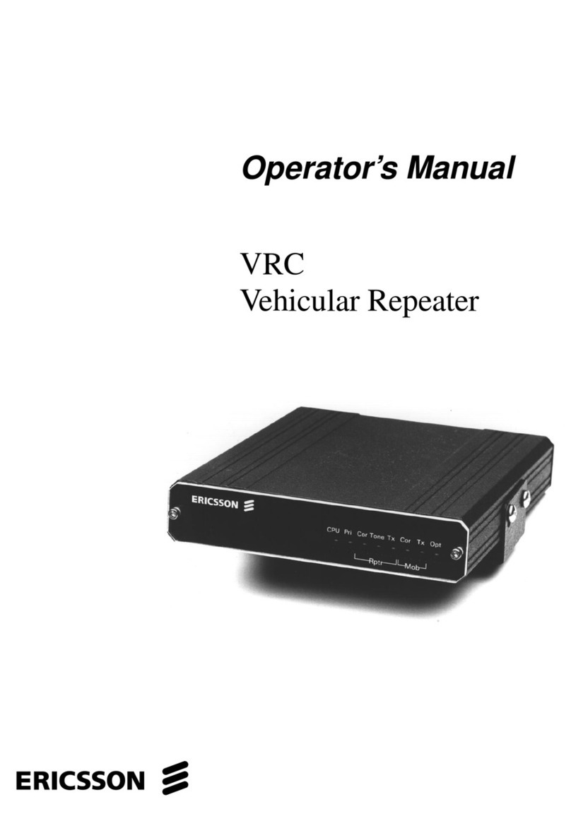
CAN bus Repeater
Firmware V2.0L

Firmware V2.0L - Doku-Version V1.9 - Current to March 2021 1
Eckelmann AG
Business Unit Refrigeration and Building Automation
Berliner Straße 161
65205 Wiesbaden, Germany
Tel.: +49 611 7103-0
Fax: +49 611 7103-133
elds-[email protected]
www.eckelmann.de
Board of Directors:
Dipl.-Ing. Peter Frankenbach (Management Spokesman),
Dipl.-Wirtsch.-Ing. Philipp Eckelmann, Dr.-Ing. Marco Münchhof
Chairman of the Supervisory Board: Hubertus G. Krossa
Deputy Chairman of the Supervisory Board: Dr.-Ing. Gerd Eckelmann
Registration court / registration number, district court Wiesbaden, Germany, HRB 12636
The current operating manual and information such as data sheets, more detailed documentation and FAQs
are available for you on-line in E°EDP (Eckelmann ° Electronic Documentation Platform) at
www.eckelmann.de/elds
You reach all relevant documents for this component directly using the QR code:
Information on safety and connection instructions are described in detail in the manual "Basics and General
Safety and Connection Instructions".
All rights to any use whatever, utilisation, further development, forwarding and creation of copies remain with
the Eckelmann AG company.
In particular, neither the contract partners of Eckelmann AG nor other users have the right to distribute or
market the IT programs/program parts or modified or edited versions without express written permission.
To some extent, names of products/goods or designations are protected for the respective manufacturer
(registered trademarks etc.); in any case, no guarantee is assumed for their free availability/permission to
use them. The information provided in the description is given independently of any existing patent protection
or other third-party rights.
Before commissioning and use, please check that this is the latest version of the
document.With the publication of a new version of the documentation, all previous
versions lose their validity. Errors and technical modifications are expressly
reserved.

Firmware V2.0L - Doku-Version V1.9 - Current to March 2021 2
1Technical safety information...................................................................................3
2Function of the CAN bus Repeater.........................................................................4
2.1 Sample applications........................................................................................................................... 5
3Installation and Commissioning of the CAN Bus Repeater.....................................6
3.1 Installation and connection to the CAN bus.......................................................................................6
3.2 Wire assignment for male connectors in the CAN bus ...................................................................... 7
3.3 Commissioning................................................................................................................................... 8
3.4 Indication of the Operating Status...................................................................................................... 8
4Specifications CAN bus Repeater ..........................................................................9
4.1 Electrical data.....................................................................................................................................9
4.2 Mechanical data................................................................................................................................. 9

Firmware V2.0L - Doku-Version V1.9 - Current to March 2021 3
1 Technical safety information
1. Commissioning and operation of the device may only be performed by qualified
personnel. "Qualified personnel" as defined by this technical safety information
means persons who have the authorisation to start up, earth and designate devices,
systems and electric circuits in accordance with security technology standards.
2. Mounting, positioning and wiring may only be conducted when the electricity
supply to the assembly has been cut off.
3. The faultless and safe operation of the product presupposes proper transport,
appropriate storage, positioning and assembly, as well as careful operation and
maintenance.
4. Voltage must only be supplied by VDE-tested and CE-certified power packs.
5. Ensure that the voltage supply and the data cable are correctly connected.
6. If the product is brought into the working area from a cold environment,
condensation may form. The product must be completely dry before being
commissioned. Do not assemble or install the product near water or in damp
surroundings.
7. Do not take the product apart or remove the enclosure. The guarantee rights will
become invalid if the housing is opened.

Firmware V2.0L - Doku-Version V1.9 - Current to March 2021 4
2 Function of the CAN bus Repeater
The CAN bus repeater extends the CAN bus within the E*LDS system by a further 500 m, see the operating
instruction introductory chapter in the E*LDS documentation), see operating instruction „E*LDS for
systematic cooling - Basics and general safety and connection instructions“ of the der E*LDS documentation.
In this process, CAN bus data from the first (primary) CAN bus segment is transformed in a second
(secondary) CAN bus segment. In order to implement the CAN bus protocol from the primary side on the
secondary side, and the reverse, the CAN bus repeater is equipped with its own microcontroller.
Note: The determination „First CAN bus segment“ resp. „Second CAN bus segment “ is scalable.
CAN bus Repeater (order No. KGLZCANREP)
Interfaces
2 x CAN bus in accordance with ISO/DIS 11 898
Voltage supply
The CAN bus repeater is powered by an external 24 V DC power pack, order No. KGLNT24V1P.
A maximum of 2 CAN bus repeaters can be employed in an E*LDS system, for
further details see the introductory chapter in the E*LDS documentation.

Firmware V2.0L - Doku-Version V1.9 - Current to March 2021 5
2.1 Sample applications
NK=NT TK=LT

Firmware V2.0L - Doku-Version V1.9 - Current to March 2021 6
3 Installation and Commissioning of the CAN Bus Repeater
3.1 Installation and connection to the CAN bus
Before commissioning, the CAN bus repeater must first be connected to the first CAN bus segment via the
front COMBICON plug. The second CAN Bus segment is then connected to the top connections of the CAN
bus repeater. Finally, the device is supplied with 24 V DC power (power pack, order number KGLNT24V1P):
Example:
Picture 3.1: Connection of the CAN bus-repeater
Note: The determination „First CAN bus segment“ bzw. „Second CAN bus segment “ is scalable.
* The start and end of a CAN Bus segment must each be connected to a terminating
resistor R=100 Ohm (0.25 W)!
Tip: Use connector set with terminating resistor to terminate the CAN bus,
order No. KGLCANTERM.

Firmware V2.0L - Doku-Version V1.9 - Current to March 2021 7
3.2 Wire assignment for male connectors in the CAN bus
CAN bus Wire/
colour
COMBICON- plug
e.g. System centre,
UA 400, VS 3010,
WR 300
CAN bus Repeater Comments
SHLD SHLD 1 --- Connect shield (SHLD) to
earthing clamps,
see chapter 3.1.
CAN-
GND green 2 G (COMBICON, front)
GND (top terminal) ---
CAN-
LOW brown 3 L (COMBICON, font)
C-L (top terminal) The start and end of a CAN bus
segment must each be connected
to a terminating resistor
R=100 Ohm (0.25 W) !
CAN-
HIGH white 4 H (COMBICON, front)
C-H (top terminal)
Connetion to e.g. Connection to
System centre / UA 400 / VS 3010 / WR 300 CAN-Bus-Repeater
Assignment of the COMBICON plug (depicted without looping and terminating resistor 100 Ohm)
CAN bus cable type: LiYCY 2x2x0,75 mm“ – twisted pair,
see the introductory chapter in the E*LDS documentation.
Details for the connection to the CAN bus are contained in the introductory chapter
of the E*LDS documentation (e.g. specification of the cable type, permissible cable
length, required terminating resistor, the correct routing and the max. number of
CAN bus repeaters).
Incorrect shielding can lead to electromagnetic noise fields.
During wiring it must be ensured that the cables with shielding are correctly
connected.

Firmware V2.0L - Doku-Version V1.9 - Current to March 2021 8
3.3 Commissioning
The commissioning of the CAN bus repeater consists of the following steps:
1. Connect the CAN bus repeater to the first and second CAN bus circuits, see chapter 3.
2. Attach the CAN bus repeater to the power supply 24 V DC.
3.4 Indication of the Operating Status
The CAN bus repeater is equipped with a display element consisting of a yellow and a green LED with the
following functions:
•Yellow LED (BA) = CAN bus status
Flickering yellow LED:
The CAN bus repeater is transmitting data via the first (primary) CAN bus segment.
•Green LED (ON) = operating voltage
Flickering green LED:
The CAN bus repeater is transmitting data via the second (secondary) CAN bus segment.
•Both LEDs are flashing at 0.5 second intervals:
The processor is running, no data is being transmitted via the CAN bus.
•Both LEDS are extinguished:
- No 24 V DC voltage supply or
- CAN bus OFF: The device is receiving data but is not able to re-transmit it.
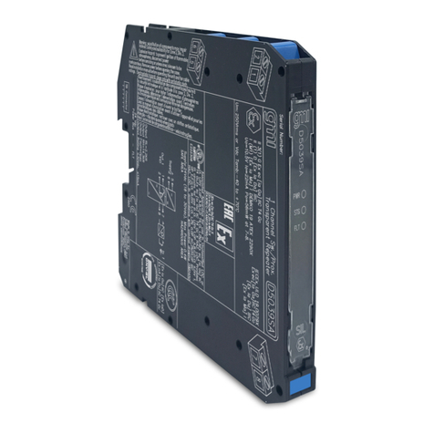
Front of the CAN bus repeater with status LEDs and 3-pole COMBICON plug

Firmware V2.0L - Doku-Version V1.9 - Current to March 2021 9
4 Specifications CAN bus Repeater
4.1 Electrical data
Technical data CAN bus repeater
Order No. KGLZCANREP
Physical interface CAN Bus in accordance with ISO/DIS 11 898
Transmission rate 50 kBit/s
Voltage supply 24 V DC, max. 100 mA, separate power supply required,
order No. KGLNT24V1P
Status display 2 x LEDs (yellow / green)
Electrical isolation 1 kV DC via optocoupler and DC/DC converter
Temperature range - in operation 0..+55 °C
max. 95 % humidity without condensation
Temperature range - storage 0..+70 °C
Enclosure Plastic, for DIN rail mounting, IP20
CE conformity Manufacturer’s CE declaration of conformity
4.2 Mechanical data
Technical modifications and errors reserved!
Table of contents

