Eclipse Algas-SDI POWER Series Manual

Operations & Maintenance
Manual
...Innovative liquid vaporizing and gas mixing solutions
151 South Michigan Street, Seattle, Washington, USA 98108
Tel: 206-789-5410 Fax: 206-789-5414 Web: www.algas-sdi.com
FILE: Manual PN 52632 Rev 08-08-07 Power.doc

Algas-SDI Operations & Maintenance Manual P/N 52632 1-1
Introduction
1
DESCRIPTION
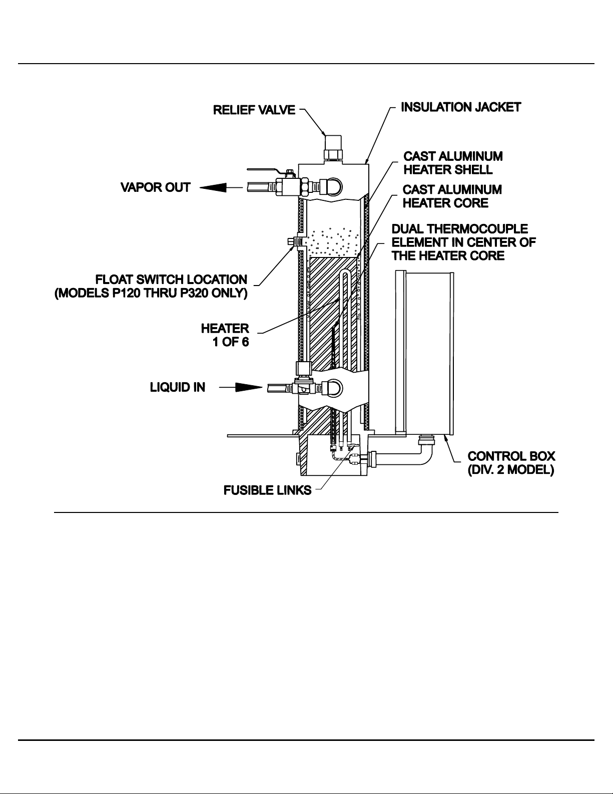
The Algas-SDI POWER Series Vertical Electric Vaporizer heats liquid propane
and transforms it from a liquid to a vapor. The Power Series vaporizers are
“indirect fired”, meaning no open flame is involved in the heating process.
The vaporizers are Factory Mutual and CSA approved and comply with Class I,
Division 1 or Division 2, Group D requirements as specified in NFPA Pamphlet
58. An annotated cut-away drawing of a single unit vaporizer is shown in
Figure 1. Six tubular heater elements are cast into the aluminum heater core.
These elements provide the heat required to vaporizer the LPG. A dual sensor
thermocouple is located in the center of the heater core. One sensor monitors
the heater core temperature and controls the heater ON and OFF cycles.
A second sensor acts as a high temperature safety and shuts the vaporizer off
if an over-temperature situation occurs. A High Liquid Level Safety Float Switch
is integral to each vaporizer. In case of liquid propane build-up in the pressure
vessel due, for example, to demand in excess of the vaporizer’s capacity, the
float will shut the vaporizer off. This will prevent liquid propane carry-over.
Two basic safety devices eliminate the possibility of over-pressurization of the
vaporizer. Over-pressure during normal operation relieves through the Solenoid
Valve and returns to the tank. Abnormal over-pressure relieves
to the atmosphere through a 250 psig (17.58 kg/cm2) pressure Relief Valve.
Three high temperature safety devices protect against over-heating of the
vaporizer. These safety devices are 2 High Temperature Limits on the Control
Board, 1 software shutdown and 1 hardware shutdown and FUSIBLE LINKS on
the heaters.

Introduction
1-2 Algas-SDI Operations & Maintenance Manual P/N 52632
Figure 1 – Typical Configuration Drawing
Control System.wmf

Algas-SDI Operations & Maintenance Manual P/N 52632 2-3
Major Component
2
Figure 2 – Vaporizer Major Components - Division 1 Models
Major Components (1).dxf
1. Vapor outlet isolation valve 7. Control panel
2. Liquid inlet manifold 8. Relief valve
3. Liquid inlet isolation valve 9. Liquid level safety switch
4. Liquid inlet safety solenoid valve 10. Outlet vapor header
5. Outlet manifold pressure gauge 11. Liquid inlet strainer
6. Outlet temperature gauge 12. Vaporizer heater core

Major Components
______________________________________________________________________________________
2-4 Algas-SDI Operations & Maintenance Manual P/N 52632
Figure 3 – Vaporizer Major Components - Division 2 Models
Major Components (2).dxf
1. Vapor outlet isolation valve 7. Control panel
2. Liquid inlet manifold 8. Relief valve
3. Liquid inlet isolation valve 9. Liquid level safety switch
4. Liquid inlet safety solenoid valve 10. Outlet vapor header
5. Outlet manifold pressure gauge 11. Liquid inlet strainer
6. Outlet temperature gauge 12. Vaporizer heater core

Major Components
______________________________________________________________________________________
Algas-SDI Operations & Maintenance Manual P/N 52632 2-5
1
Figure 4 – Control Box Major Components - Division 1 Models
Control Box (1).dxf
1. Start pushbutton (momentary) 5. Transformer/solenoid valve fuses
2. Control board 6. Input power distribution blocks
3. Stop pushbutton (momentary) 7. Hermetically Sealed Heater control relay
4. Transformer-Control Board/Solenoid Valve

Major Components
______________________________________________________________________________________
2-6 Algas-SDI Operations & Maintenance Manual P/N 52632
Figure 5 – Control Box Major Components - Division 2 Models
Control Box (2).dxf
1. Indicator lamps 7. Single float switch PC board
2. ON/OFF switch (maintained) 8. Line power distribution block
3. Start pushbutton (momentary) 9. Heater protection fuses
4. Transformer/solenoid valve fuses 10. Ground lug
5. Control board 11. Hermetically Sealed Heater control relay
6. Transformer-Control Board/Solenoid Valve

Algas-SDI Operations & Maintenance Manual P/N 52632 3-7
Installation
3
WARNING
The equipment described in this manual is designed to operate with
LP-gas, a flammable fuel under pressure. The nature of the
application involves inherent hazards that could result in injury.
ONLY a trained and fully qualified person should service this
equipment.
GENERAL
Installation requirements vary according to local, provincial, and state
requirements. Requirements often differ from those provided in NFPA
Pamphlet 58. Consult the authorities having jurisdiction over your installation.
A drawing of a typical installation of a Power Series Vertical vaporizer can be
found below. Install the ASDI Power vaporizer on a firm, level base. Bolt it
securely through the four mounting holes in the vaporizer stand base plate.
Adequately shield the vaporizer installation against vehicular damage. Prior to
making the final piping connections, clean all foreign material from the pipes.
All piping joints should be made up using joint compound approved for LP-Gas.
Carefully test the completed piping connections for leaks using a COMPRESSED
INERT GAS and a soapy solution. Carbon dioxide or nitrogen applied at
approximately 100 psig ( 7.03 kg/cm2 ) work well as testing agents. Remember a
bubble indicates a leak! Even a tiny bubble is unacceptable! NO LEAK IS
TOLERABLE! Repeat the test process until all leaks are eliminated.

Installation
3-8 Algas-SDI Operations & Maintenance Manual P/N 52632
Figure 6 – Installation Drawing with Pump
Installation.dxf
Figure 6B – Typical Installation Drawing with Vapor Bypass and No Pump
Installation (B).dxf

Installation
Algas-SDI Operations & Maintenance Manual P/N 52632 3-9
Figure 6C – Typical Installation Drawing with Economy and Vapor Bypass
Installation (C).dxf
NOTE
The vapor bypass line is not required except when you have the
Economy Operation option. In other installations, it is
recommended because it will provide vapor from the tank to the
load in case of vaporizer failure or power failure but it is not
required. The vaporizer will operate properly without the bypass.
LIQUID LINE PIPING
The liquid line from the storage tank to the vaporizer should be Schedule 80 steel
pipe and must incur a minimal pressure drop while supplying the vaporizer at
capacity operation. Table 1 provides a handy guideline to assist in determining
the appropriate pipe size for a given size vaporizer over a given distance. Install
a liquid line strainer with a magnet for iron particle pickup upstream of the
vaporizer.
WARNING
Propane flows in both directions in the Liquid Line. This allows the
vaporizer and storage tank to maintain a “Pressure Balance”.
Never install a check valve in the liquid propane line!
CAUTION
A liquid pump must be installed if the pressure drop in the liquid
line between the vaporizer and the tank exceeds the hydrostatic
liquid head in the storage tank. ONE FOOT OF LIQUID PROPANE
EQUALS 0.21 psi ! Liquid line frosting is a sure indication of too
much pressure drop in the liquid line.

Installation
3-10 Algas-SDI Operations & Maintenance Manual P/N 52632
Table 1 – Sizing Chart for Liquid Propane Supply Lines to Vaporizers
(use schedule 80 steel pipe or approved equal)
Capacity of Units Distance in feet from Storage to Vaporizer
MMBTU GPH 100 200 300 400 500 750 1000 2000
20.0 220 1 ¼” 1 ¼” 1 ½” 2” 2” 2” 2” 2 ½”
30.0 330 1 ¼” 1 ½” 2” 2” 2” 2” 2 ½” 2 ½”
40.0 440 1 ¼” 1 ½” 2” 2” 2” 2” 2 ½” 2 ½”
50.0 550 1 ½” 2” 2” 2” 2” 2” 2 ½” 2 ½”
60.0 660 2” 2” 2” 2” 2” 2 ½” 2 ½” 2 ½”
80.0 880 2” 2” 2” 2” 2” 2 ½” 2 ½” 3”
100.0 1100 2” 2” 2” 2” 2 ½” 2 ½” 2 ½” 3”
150.0 1640 2” 2” 2” 2 ½” 2 ½” 2 ½” 3” 3”
200.0 2200 2” 2” 2 ½” 2 ½” 2 ½” 3” 3” 3 ½”
300.0 3300 2” 2 ½” 2 ½” 2 ½” 3” 3” 3 ½” 4”
400.0 4400 2 ½” 2 ½” 2 ½” 3” 3” 3 ½” 4” 4”
500.0 5500 2 ½” 3” 3” 3” 3 ½” 4” 4” 4”
750.0 8200 3” 3” 3” 3 ½” 4” 4” 5” 5”
1000.0 10950 3” 3 ½” 3 ½” 4” 4” 5” 5” 6”
NOTE
Per NFPA 58, a storage tank shall have piping downstream large
enough to assure closure of the excess flow valve if the pipe is
ruptured. If the pipe is too small to allow this flow, it must be
protected downstream with an excess flow valve.

Installation
Algas-SDI Operations & Maintenance Manual P/N 52632 3-11
Table 2 – Liquid Temperature vs. Tank Pressure Chart
Propane Butane Ammonia
Liquid
Temperature
Tank Gauge
Pressure
Tank Gauge
Pressure
Tank Gauge
Pressure
°F °C psi KPa psi KPa psi KPa
-43.73 -41.65 0 0
-40 -39.6 1.3952 9.6196
-30
-36.85
3.421
23.5871
-30 -34.1 5.639 38.877
-25 -31.35 8.06 55.57 1.234 8.511
-20 -28.6 10.697 73.751 3.539 24.401
-15 -25.85 13.561 93.503 6.156 42.648
-10 -23.1 16.666 114.91 8.968 61.834
-5 -20.35 20.024 136.06 12.216 84.228
0 -17.6 23.648 163.05
NOTE:
Below 30°F or -10°C,
Butane is a liquid at normal
Atmospheric pressure. 15.622 107.710
5 -14.85 27.551 189.96 19.565 134.893
10 -12.1 31.747 218.88 23.688 163.323
15
-9.35
36.248
249.92
28.424
195.977
20 -6.6 41.068 283.15 33.366 230.051
25 -3.85 46.222 318.69 39.001 268.899
30 -1.1 51.723 356.67 44.867 309.347
35 1.65 57.586 397.04 1.25 8.6185 51.513 355.168
40
4.4
63.825
440.06
2.92
20.133
58.418
402.778
45 7.15 70.455 485.77 4.82 33.233 66.035 455.295
50 9.9 77.49 534.27 6.85 47.229 74.254 511.963
55 12.65 84.945 585.68 9 62.053 83.106 572.996
60 15.4 92.836 640.08 11.32 78.049 92.622 638.606
65
18.15
101.179
697.6
13.82
95.286
102.84
709.057
70 20.9 109.988 758.34 16.5 113.76 113.78 784.486
75 23.65 119.28 822.4 19.3 133.07 125.49 865.223
80 26.4 129.0715 889.91 22.44 154.72 137.99 951.408
85 29.15 139.737 963.45 25.81 177.95 151.33 1043.384
90
31.9
150.215
1035.7
29.21
201.4
165.54
1141.358
95 34.65 161.603 1114.21 32.67 225.25 181.12 1248.778
100 37.4 173.558 1196.64 36.67 252.83 196.7 1356.199
105 40.15 186.098 1283.1 41.02 282.82 214.235 1477.098
110 42.9 199.241 1373.72 46.57 321.09 231.77 1597.998
115
45.65
213.007
1468.63
50.28
346.67
251.415
1733.445
120 48.4 227.414 1567.96 55.28 381.14 271.06 1868.893
125 51.15 242.483 1671.86 60.53 417.34 292.97 2019.957
130 53.9 258.235 1780.47 66.13 455.95 314.88 2171.021
135 56.65 274.691 1893.93 72.13 497.32 339.21 2338.771
140 59.4 291.875 2012.4 78.17 538.96 363.54 2506.520

Installation
3-12 Algas-SDI Operations & Maintenance Manual P/N 52632
LIQUID PUMP
Is a Liquid Pump necessary? What are your vapor pressure requirements?
Pressure in the storage tank depends on temperature ( See Table 2 ). A good
“rule of thumb” for determining when a Liquid Pump is necessary is this: If the
storage pressure will not always exceed the required distribution pressure by 5
psig ( 0.35 kg/cm2 ), a pump is necessary. Install an ASDI STABILAIRE LIQUID
PUMP in the liquid line close to the storage tank. To prevent cavitation, place the
liquid strainer at least five feet upstream of the pump inlet. Typically a pump is
not required unless a mixing system is used or temperature at the installation will
be extremely low, causing the pressure to drop below the pressure the required
process pressure.
VAPOR LINE
Install an appropriate regulator immediately downstream of the vapor outlet port.
Pipe from the outlet port of the regulator to the distribution system. Further
reduction of downstream pressure requires a “Second Stage” regulator close to
the consuming equipment. Properly sized piping and regulators will insure
satisfactory service.
NOTE
For safety reasons both FIRST and SECOND stage regulators must
be 250 psig ( 17.58 cm/kg2 ) inlet pressure rated!
SAFETY RELIEF VALVE
If the vaporizer is installed within an enclosure or building, VENT THE SAFETY
RELIEF VALVE OUTSIDE THE ENCLOSURE AND REDIRECT THE
DISCHARGE UPWARD. An optional breakaway adapter is required for piping
from the relief valve. Always install a rain-cap or similar device to prevent water
and other debris from entering the relief discharge. If water enters, it may freeze
and prevent the relief valve from proper discharge, creating a potentially
hazardous situation.
ELECTRICAL SERVICE
The Nameplate on the vaporizer and the Data Sheet provided with the manual
provides your specific vaporizer’s electrical power requirements and the drawing
numbers of the appropriate wiring diagrams and schematics. This unit is
constructed to meet NFPA 70 Class I, Division 1 or Division 2, Group D
requirements. All wiring to the unit, including the ground connection, must meet
the applicable codes for the area in which it is being installed. Wire size and type
must comply with the applicable codes for the area in which it is being installed.
Provide a fused disconnect outside of the classified area. If it is not within sight
of the vaporizer, the fused disconnect must have a locking device. Run wire
within rigid conduit, and install a seal-off at the connection of the field conduit to
the vaporizer.

Installation
Algas-SDI Operations & Maintenance Manual P/N 52632 3-13
DETERMINING WIRE SIZE
When selecting the type and size of wire used to install the POWER Series
electric vaporizers, please take into account the following information:
■Current draw of vaporizer and distance of vaporizer from the disconnect: See
vaporizer Nameplate or the Data Sheet for specific information for the
vaporizer.
■Single Vaporizer with 60 / 100 amp:
Contactor terminal lug wire size range: #2 - 8 AWG
■Division 1 Multiple Vaporizer (1-12) 380V to 575V:
Contactor terminal lug wire size range: #2 - 8 AWG
Power is applied to each individual control boxes 1-12.
■Division 2 Multiple Vaporizer (2-4) 380V to 575V:
Power distribution terminal lug wire size range: 350MCM - 6 AWG
Branch distribution terminal lug wire size range: #6 - 14 AWG
■Division 2 Multiple Vaporizer (5-6) 380V to 575V built in 2007 forward:
Power distribution terminal lug wire size range: 500MCM - 2 AWG
Branch distribution terminal lug wire size range: #4 - 14 AWG
Applies to 2 separate control boxes.
■Division 2 Multiple Vaporizer (5-8) 380V to 575V ( applies to units built before
2004):
Power distribution terminal lug wire size range: 2 - 500MCM - 2 AWG
Branch distribution terminal lug wire size range: #4 - 14 AWG
As the length of the wire run affects the overall wire size requirements, always
refer to NFPA 70 (NEC) for proper wire selection.
When installing the wire it is important to have a good connection at the terminal
lugs. Loose terminations may cause an excessive temperature rise at the
terminal lugs, which can lead, to premature contactor failure, transformer failure,
and/or overheating and possible destruction of the transformer. For this reason it
is strongly recommended that the wire terminations be checked and re-tightened
periodically to prevent excessive overheating at the terminals due to loose
connections.

Algas-SDI Operations & Maintenance Manual – P/N – 52632 4-15
Operation
4
WARNING
The equipment described in this manual is designed to operate with
LP-gas, a flammable fuel under pressure. The nature of the
application involves inherent hazards that could result in injury.
ONLY a trained and fully qualified person should service this
equipment.
System Control Description
The electric vaporizer operates by maintaining a finned aluminum heater core at
an operating temperature. The heater core consists of multiple cast-in resistance
heater elements. Multiple wiring configurations allow a variety o AC input
Voltages to suit local power supply requirements.
Liquid LPG enters the vaporizer through an inlet safety solenoid valve at the
base of the pressure vessel. The solenoid is normally closed valve. The
solenoid opens at a preset temperature after initial start-up, and remains open
under normal operation. Any safety violation causes the solenoid to de-energize
(close). The liquid LPG that comes in contact with the heated core absorbs the
heat, vaporizes, and cools the core. The heaters then come on as necessary to
keep the core temperature above 194°F ( 90°C ). The amount of LPG that can
be vaporized depends directly on the amount of heat that the core can produce.
The amount of heat that the core can produce depends on the size ( wattage ) of
the heaters and the power (voltage) available to produce the heat. Other factors
such as pressure and temperature also affect the amount a vaporizer can
vaporize.
The core temperature-sensing device is a dual thermocouple inserted in the
center of the aluminum core. The thermocouple signal is used to turn the
heaters on and off, turn the solenoid valve on during initial startup, and sense for
over-temperature conditions by the control board. The control board also
monitors a liquid level switch to shut off the vaporizer if it cannot keep up with the
demand for vaporized LPG. The control board turns the mercury relay on and off
to apply power to the heaters as needed for temperature control.
STOP! Have you rechecked the wiring,
tested for leaks, and made sure the
vaporizer is properly installed???

Operation
4-16 Algas-SDI Operations & Maintenance Manual P/N 52632
Figure 7 – Control System
Control System.wmf
Control Board
BROWN-OUT FEATURE
The vaporizer is equipped with a Brown-Out feature. The Brown-Out feature will
return the vaporizer to normal operation if there is a power disturbance that is
less than 5 seconds. Do not get the Brown-Out feature confused with the Auto
Restart Option. The Brown-Out feature will only maintain vaporizer operation for
power disturbances less than 5 seconds. The Auto Restart Option will restart the
vaporizer if there is a loss of power for more than 5 seconds. If the vaporizer
should shut down on a safety during the above procedure, open the control box
and read the Operation / Fault code on the annunciator in the upper left corner of
the control board. The annunciator should display a failure code for reference in
troubleshooting. Follow the troubleshooting procedures in this manual to
determine the cause of the problem.
NOTE: Vaporizer controls prior to 53050-X series control board do not have a
brown-out feature.

Operation
Algas-SDI Operations & Maintenance Manual – P/N – 52632 4-17
NEW - AUTO RESTART AND ANNUNCIATOR FUNCTIONS
A new revision of the control board was introduced in fall of 2004. This revision
of the control board is backward compatible with previous control boards. The
control board will feature a EEPROM memory chip. This EEPROM memory chip
will allow the controls to retain failure codes when the ON/OFF switch is set to
OFF or the STOP button is pushed, or main power lost. On any failure
occurrence, the AUTO RESTART feature will be disabled and will not allow the
vaporizer to restart when power returns. For units with STOP/START push
buttons with AUTO RESTART, pushing the STOP button will latch the vaporizer
off. The vaporizer will remain off even if main power is cycled. Pushing the
START button starts the vaporizer and allows the AUTO RESTART feature to
resume normal operation. Any failure code will be reset once the problem is
resolved and the START button is pushed. See the Troubleshooting Section
in the manual for more troubleshooting help.
NEW - ADDED AUTO RESTART DELAY
The AUTO RESTART will have a 2 second delay before starting the vaporizer.
This will allow adequate time for the power to stabilize and for any externals
components to re-energize. The Display Lamps will remain blank for 2 seconds,
then will light as the unit starts up. If the vaporizer is on and power is lost or
drops for less than 5 seconds, the vaporizer will immediately restart. This is
normally referenced as a Brown-Out.
NEW - INCREASED SWITCH BOUNCE DELAYS
This new revision will also have increased switch input bounce delay. The Float
Switch, Economy Pressure Switch Option and the Down Stream Pressure Switch
( AUTO RESTART ) inputs have 2 second delays. The Float Switch will have to
be open for more than 2 seconds before the vaporizer shuts down. This should
minimize any nuisance tripping due to surges or momentary load increases. The
Economy Pressure Switch Option will have to remain open for more than 2
seconds before turning OFF the Solenoid and Heater on increasing pressure.
The Economy Pressure Switch Option will have to remain closed for more than 2
seconds before turning ON the Solenoid and Heater on decreasing pressure.
The Down Stream Pressure Switch ( AUTO RESTART ) is normally configured
either always open or always closed via a jumper. However, the Down Stream
Pressure Switch input is used on special configuration as a switch input.
NOTE
This control board revision will be effective on control boards
shipped with the P/N: 53050-3 and above. ( Released September
2004 )

Operation
4-18 Algas-SDI Operations & Maintenance Manual P/N 52632
Operating Instructions
STARTING THE VAPORIZER - DIVISION 1 MODELS
CAUTION
Do not start the vaporizer when both inlet and outlet hand valves
are closed. Pressure can build in the vaporizer during startup and
blow the relief valve.
QUICK START - DIVISION 1 MODELS
1. Close all vaporizer manual outlet valves.
2. Open the manual valve(s) between the propane storage tank and the
vaporizers to allow liquid to flow to the vaporizers. At this time liquid propane
exerts pressure against the still closed solenoid valves.
3. Turn power ON at the Main disconnect.
4. Push the START button located on the left side of the control box.
8. The inlet valve will open with a distinctive “click” sound after approximately
30 seconds of warm-up.
8. Repeat steps 3 - 5 for multiple vaporizer configurations.
8. Slowly open the vaporizer manual outlet valve. Liquid propane is now
flowing into the heated vaporizers and vaporization is now occurring. The
heaters will turn on and off automatically in response to heater core
temperature to match demand.
CAUTION
Make an operational check of the inlet solenoid valve once the
vaporizer is started.
8. Press the STOP button. The valve should stop the flow of liquid as indicated
by the loss of pressure at the outlet. Pressing the START button should
immediately restore operation.
DETAILED START - DIVISION 1 MODELS
Close the outlet hand valve. Open the inlet hand valve. The division 1 units are
equipped with Auto Restart as a standard feature as of September 2004.
Vaporizers shipped before this date with control board 53050-2 and below the
Auto Restart was an Optional feature. The Auto Restart is a feature that allows
the vaporizer to Restart Automatically when the main power is disrupted. See
the Options Chapter to learn more about this feature and other Options that the
vaporizer may have before starting the vaporizer. When the power at the
disconnect is turn on the vaporizer may Automatically start due too this feature.
If not, press and release the "START" switch. From a cold start, the heaters
should come on immediately. The solenoid valve should come on after 30
seconds and the heaters should go off after 55 seconds. If the "HEAT ON" lamp
stays on longer than 55 seconds (starting with a cold unit 60°F ( 15.5°C ) or less),

Operation
Algas-SDI Operations & Maintenance Manual – P/N – 52632 4-19
it indicates a possible problem, SEE THE TROUBLESHOOTING SECTION. If
the vaporizer does not start after push the START button, SEE THE
TROUBLESHOOTING SECTION. Vaporizers equipped with the Auto Restart
option may start the vaporizer operation immediately. Vaporizers equipped with
the Economy Option may not start immediately due to high tank pressure.
If the vaporizer is equipped with additional options, See the Options Chapter to
learn more about the other Option Operations.
The vaporizer is now ready to operate.
Slowly open the outlet hand valve. The heaters should begin to cycle to meet the
demand for propane.
If the vaporizer should shut down on a safety during the above procedure, open
the control box and read the Operation / Fault code on the annunciator in the
upper left corner of the control board. Look up the Operation / Fault code on the
annunciator to find out why the vaporizer failed. Follow the troubleshooting
procedures in this manual to determine the cause of the problem.
STOPPING THE VAPORIZER - DIVISION 1 MODELS
1. Push the STOP button(s) located on the right side of the control box(s).
2. Close the manual outlet shutoff valve.
3. Extended period shutdown requires closing the liquid propane withdrawal
valve at the storage tank while there is demand on the system. This allows
the pressure to bleed out of the system. Turn power off at the Main
disconnect and shut the manual outlet valve at the vaporizer. Drain the
system at the strainer to get rid of any accumulated oil and “heavy ends”.
NOTE
Whenever the vaporizer has been turned off and allowed to cool,
the entire STARTUP PROCEDURE must be repeated. Liquid
carryover and a safety shutdown can result from failure to follow
this procedure.
NOTE
When shutting down the vaporizer, always shut off the vaporizer
outlet isolation hand valve.

Operation
4-20 Algas-SDI Operations & Maintenance Manual P/N 52632
STARTING THE VAPORIZER - DIVISION 2 MODELS
CAUTION
Do not start the vaporizer when both inlet and outlet hand valves
are closed. Pressure can build in the vaporizer during startup and
blow the relief valve.
QUICK START - DIVISION 2 MODELS
1. Close all manual outlet valves on vaporizer.
2. Open the manual valve(s) between the propane storage tank and the
vaporizers to allow liquid to flow to the vaporizers. At this time liquid propane
exerts pressure against the still closed solenoid valves.
3. Set all ON/OFF toggle switch(s) to the OFF position.
4. Turn power ON at the Main disconnect. Flip the toggle switch to the ON
position at the control panel. Observe that the POWER ON lamp lights
indicating “POWER” to the control box. The HEAT ON and VAPORIZER
OPERATING ( SAFETY CIRCUIT LATCHED ) lamps should illuminate.
5. The INLET VALVE OPEN lamps will illuminate after approximately 30
seconds of warm-up. The inlet valve will open with a distinctive “click” sound,
and its control panel indicator lamp will illuminate. Liquid propane is now
flowing into the heated vaporizers and vaporization is now occurring.
6. Repeat steps 4 & 5 for multiple vaporizer configurations.
7. Slowly open the vaporizer manual outlet valve. Liquid propane is now
flowing into the heated vaporizers and vaporization is now occurring. The
heaters will turn on and off automatically in response to heater core
temperature to match demand.
CAUTION
Make an operational check of the inlet solenoid valve once the
vaporizer is started.
8. Turn the Vaporizer OFF. The valve should stop the flow of liquid as indicated
by the loss of pressure at the outlet. Pressing the START button should
immediately restore operation.
This manual suits for next models
8
Table of contents