ECO DELTA POWER ECO-M-72S Series User manual

ECO Shingled V2.1
1/ 16
Shingled single glass crystalline silicon
PV Modules installation manual
(IEC version)

ECO Shingled V2.1
2/ 16
Crystalline Silicon Shingled Module Products Installation Manual (IEC)
Applicable products
This manual is intended for use with the following shingled modules:
Monocrystalline PV shingled modules:
ECO-xxxM-72S
ECO-xxxM-60S
Monocrystalline PERC PV shingled modules:
ECO-xxxM-78SA
ECO-xxxM-72S
ECO-xxxM-72SA
ECO-xxxM-72SB
ECO-xxxM-66SA
ECO-xxxM-60S
ECO-xxxM-60SA
ECO-xxxM-60SB
Module dimensions and electrical performance data are details in the
corresponding technical specifications.

ECO Shingled V2.1
3/ 16
1. Scope
This installation manual specifies the installation and maintenance requirements for crystalline silicon PV
modules (hereinafter referred to as "shingled modules") manufactured by ECO DELTA POWER CO., LTD.
(hereinafter referred to as "Eco Delta" ).
This installation manual is intended for the installation and maintenance of shingled modules (hereinafter
referred to as "shingled modules"), and helps customers to correctly install the photovoltaic power generation
system, so that the design system can realize its potential. This installation manual does not apply to the
installation of the Eco Delta double glass modules and conventional modules.
2. The introduction of installation manual
2.1 Overview
Thanks for choosing the crystalline silicon PV shingled module of Eco Delta Power Co., Ltd. This manual
contains important electrical and mechanical installation information. For correct installation and stable power
output, please install and maintain the modules Carefully read and understand all installation instructions in the
manual, and Keep this manual in a safe place for future reference (care and maintenance) and in case of sale or
disposal of the modules.
This manual does not constitute a warranty, expressed or implied. Eco Delta does not assume responsibility
and expressly disclaims liability for loss, damage, or expense arising out of or in any way connected with
installation, operation, use or maintenance of modules.
The PV modules should be installed in accordance with all safety precautions and local laws and regulations
of this manual and should be installed and serviced by qualified personnel with knowledge of the mechanical and
electrical requirements of the system.
The mechanical and electrical installation of the PV modules shall be made in accordance with applicable
laws and regulations, including electrical, construction and electrical connection requirements. These regulations
vary depending on the installation site, such as building roofs, surface mounts, in-vehicle applications, and so on.
The requirements may vary depending on the installation system voltage, the use of DC or AC. Please refer to the
relevant local laws and regulations.
Any questions, please contact with the salesman or customer service personnel of Eco Delta for further
explanations.
ECO Shingled V2.1
4/ 16
3. Product information
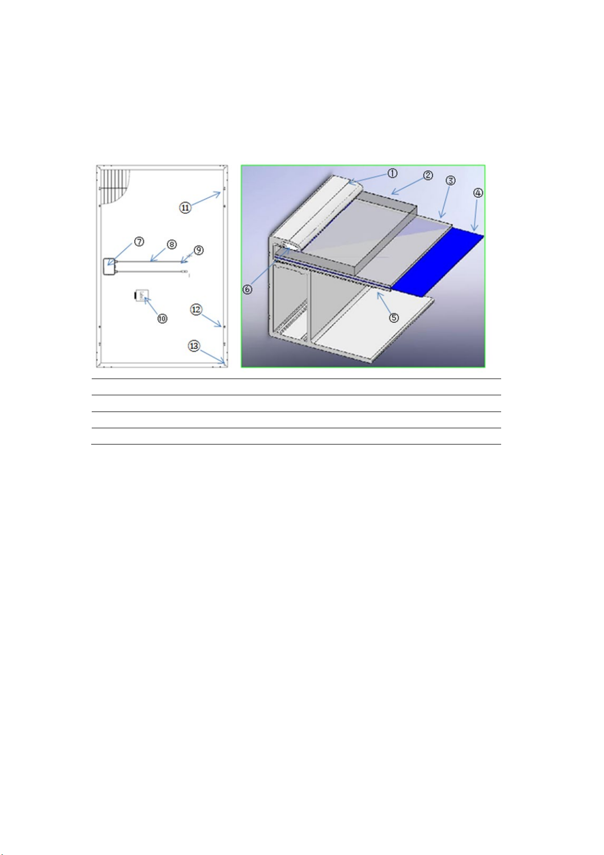
3.1 Structure and module description
1、Frame 2、Glass 3、EVA 4、Solar Cell
5、Backsheet 6、Adhsive 7、Junction box 8、Cable
9、Connector 10、Lable 11、Ground hole 12、Mounting hole
13、Drainage hole
Figure 1 Section structure and module description
3.2 Module tag information
Each PV module is affixed with two kinds of labels, providing the following information:
a) Label: Describes the product name, PV module model, nominal power, rated voltage, rated current, open
circuit voltage, short circuit current, maximum system voltage, PV module size and weight under standard
test conditions.
b) Series number: Each module has a unique bar code number, each bar code number has 20 letters and
numbers. The bar code is permanently encapsulated inside the module, as can be seen clearly from the top
right corner of the module. The bar code number allows you to trace information about the module
production process.
3.3Module electrical performance parameters
The electrical performance parameters of the module were measured under standard test conditions
(irradiance of 1000 W / m², AM 1.5 spectra, ambient temperature of 25 ° C) with a test uncertainty of ± 3%. The
maximum system module voltage is 1500V. Refer to the following table for electrical performance parameters.

ECO Shingled V2.1
5/ 16
4. Installation
4.1 General safety
4.1.1 Eco Delta’s modules have been evaluated by according to IEC61215 and IEC61730, application class A,
modules rated for use in this application class may be used in system operating at greater than 50V DC or 240W.
The safety class of the module is Class II, the class of fire rating is Class C(According to the standard is UL790),
and the maximum series fuse is 20A.
4.1.2 The installer should abide by the relevant local laws and regulations when installing module. It is need to
obtain the required certificates in advance when necessary, such as the building permit.
4.1.3 Installing solar photovoltaic systems require specialized skills and knowledge. Installation should be
performed only by qualified person. Installers should assume the risk of all injuries that might occur during
installation, such as electric shock.
4.1.4 Photovoltaic modules are designed for outdoor use. Modules may be mounted on ground, rooftops, vehicles
or boats. Proper design of support structures is the responsibility of the system designers or installers. When
modules are mounted on rooftops, fire-protection rating of the final structure should be considered, and also the
later maintenance. The rooftops and support structure for PV system should only be certified by architectural
experts or engineer, which have a formal complete structure analysis results.
4.1.5 For your safety, do not install the modules without safety precautions.
4.1.6 For your safety, do not install or handle the modules under wet or adverse environment, including but not
limited to strong wind, gusty wind, frosted roof surfaces, wet environment.
4.2 Electrical properties safety
4.2.1 When a module is exposed to sunlight or other light sources, a direct current is present inside the module,
and electrical contact with the module may result in an electrical shock hazard.
4.2.2 In order to avoid arc and electric shock, please do not disconnect electrical connections under load. Keep all
electrical connectors dry and clean, and ensure that they are in proper working condition. Do not insert other metal
objects into the connector, or in any other way.
4.2.3 Do not apply paint or adhesive to module surface. Do not wipe modules with corrosive chemicals.
4.2.4 Do not use mirrors or other magnifiers to focus sunlight on the modules. Do not expose the backside of
modules directly to sunlight for a long time.
4.2.5 Do not change the configuration of the bypass diodes. Do not disassemble the modules.
4.2.6 Do not contact with module surface when the module is wet unless to clean the modules, please following
requirements mentioned in this manual when cleaning.
4.3 Handling safety
4.3.1 Do not open the box until it reaches the installation location. Keep the package in a dry and dry place.
4.3.2 PV modules Unpacking Please refer to Unpacking manual of standard package of Eco Delta photovoltaic
modules. During all handling procedures, make sure that the modules are not subject to large vibrations, that the
modules fall to the floor or that objects fall on the module, as this will Damage to the modules or solar cell.
Special care must be taken not to bump, scrape, or press against the back of the module. Keep children and
unauthorized person away from the modules while transporting or installing them. Improper transportation or
placing may lead to glass breakage or power loss of the modules, resulting in the loss of the use value of modules.
4.3.3 Handle modules with care, lift and put down modules gently. It is forbidden to carry or lift the modules by
grabbing the junction box or cables. Two or more people must hold the module with both hands.

ECO Shingled V2.1
6/ 16
4.3.4 Do not step on, stand or sit on the module, which can damage the module and create a risk to people.
4.3.5 Do not place any heavy objects on the front or back of the module, and do not place the module on a sharp
object surface.
4.4 Installation safety
4.4.1 Abide by the safety regulations for all other modules used in the PV system, including wiring and cables,
connectors, controllers, inverters, storage batteries, etc., and use suitable equipment, connectors, wiring and
mounting system for a PV system. If the PV system is used in storage batteries, the configuration with the
modules should follow the advice of the storage batteries manufacturer. The same size, the same specifications of
the model can be connected in series.
4.4.2 Do not install or handle the modules when they are wet or during strong wind. Keep the junction box’s cover
closed.
4.4.3 Modules of the glass with the role of protection modules, unreasonable operation will cause glass broken.
Damaged modules have the risk of electric shock and fire, such modules can not be repaired or repaired, should be
replaced immediately.
4.4.4 When exposed to direct sunlight, one individual solar module may generate DC voltages greater than 30
volts. It is extremely dangerous to contact it.
4.4.5 To reduce the risk of electric shock or burning, you can install modules with opaque material on the surface
of the module. The mounting of the array of modules must be carried out with an isolating solar installation. Do
not wear metal rings, watches, earrings and other metal accessories when installing or servicing PV systems. Do
not touch the electrical parts of the module directly by hand. Use an insulating tool to make electrical connections
and keep the tool dry.
4.4.6 The triangle hole punched on the backside frame of the module is the drainage hole which cannot be
blocked.
4.4.7 The maximum system voltage indicated in the rating label is 1500 V. During the system Installation, the
maximum open circuit voltage in series cannot exceed the maximum system voltage.
4.4.8 During modules interconnection, ensure to fix the connecting cables to supporting bracket, so as to restrict
the swing amplitude of the slack part of the cables.
4.4.9 Abide by the allowable minimum bending radius of the cables (suggest no less than 43mm).
4.4.10 Always protect the cable with conduit where animals or children can touch it.
4.4.11 Please use the connector which is specially designed for photovoltaic system, and assemble it with the tools
recommended or specified by the manufacturer. In case that the connector applicable to the solar photovoltaic
system is required, please contact the local supplier. Ban different connectors to plug each other.
4.4.12 Make sure that the polarity is correct when connecting the module with inverter, storage battery or
combiner box to avoid the damage of bypass diodes in the modules due to incorrect polarity.
4.4.13 Do not drill holes in the frame, this may reduce the mechanical load ability and cause corrosion of the
frame.
4.4.14 Do not scratch the anodized coating of the frame (except for grounding connection), this may cause
corrosion of the frame or reduce the mechanical load ability.
4.4.15 Modules can't be used to replace the roof and wall materials, partial replacement is not allowed.
4.4.16 Any part (including nameplate) of modules supplied by Eco Delta Power Co., Ltd can't be dismantled
without permission.

ECO Shingled V2.1
7/ 16
5. Installation condition
5.1 Working environment
Eco Delta’s PV module should operate in the following environmental conditions:
5.1.1 Ambient temperature: -20℃ to +45℃
5.1.2 Operating temperature of the module: -40℃ to +85℃
5.1.3 Humidity: 85%RH
5.1.4 Mechanical load bearing capacity: the modules have passed the mechanical load test of wind pressure of
2400Pa and snow pressure of 5400Pa; at the same time, they have passed the mechanical load test of wind
pressure of 3600Pa and snow pressure of 3600Pa. (Only limited to the PV module models mentioned in this
manual).
Note: The module mechanical load is based on the installation method and installation site, in the calculation of
mechanical load by the professional installer according to the system design requirements to calculate.
5.2 Installation position
5.2.1 In most applications, PV modules should be installed in a location where they will receive maximum
sunlight throughout the year. In the northern hemisphere, modules should typically face south, and in the southern
hemisphere, modules should typically face north.
5.2.2 The module shall be installed in the place where the sunshine is adequate. the module surface shall not be
partly shaded by trees, building, clothes, tools, packaging materials, etc. because these objects will form shadow
in the module surface leading to loss of system output power.
5.2.3 The module shall be installed in the well-ventilated place; meanwhile, enough space for airiness shall be
sated at the back and sides of the module, so that the heat generated during operation can be radiated in time.
5.2.4 Modules can not be used in other excessive and harsh environments, such as hail, snow, sand, smoke, air
pollution, soot, flammable gases, near open flames, and highly corrosive substances (salt, salt spray, salt water,
acid rain) , As this will affect the module's safety and performance. If the installation environment is special, such
as the seaside, farm, high humidity or wind and other large environment, please consult your local dealer for
professional support and confirmation. If you need to be installed at a high altitude, the altitude should not exceed
2000m.
5.2.5 Modules should be installed in suitable buildings, or other suitable place to install modules (such as the
ground, garage, building facades, roof).
5.2.6 If modules are installed in locations with frequent lightning activity, the modules must be protected against
lightning strikes.
5.2.7 Do not install the modules in this location with water immersion or near the sprinkler.
5.2.8 The pressure of the wind or snow after installation of the modules must not exceed the maximum allowable
load.
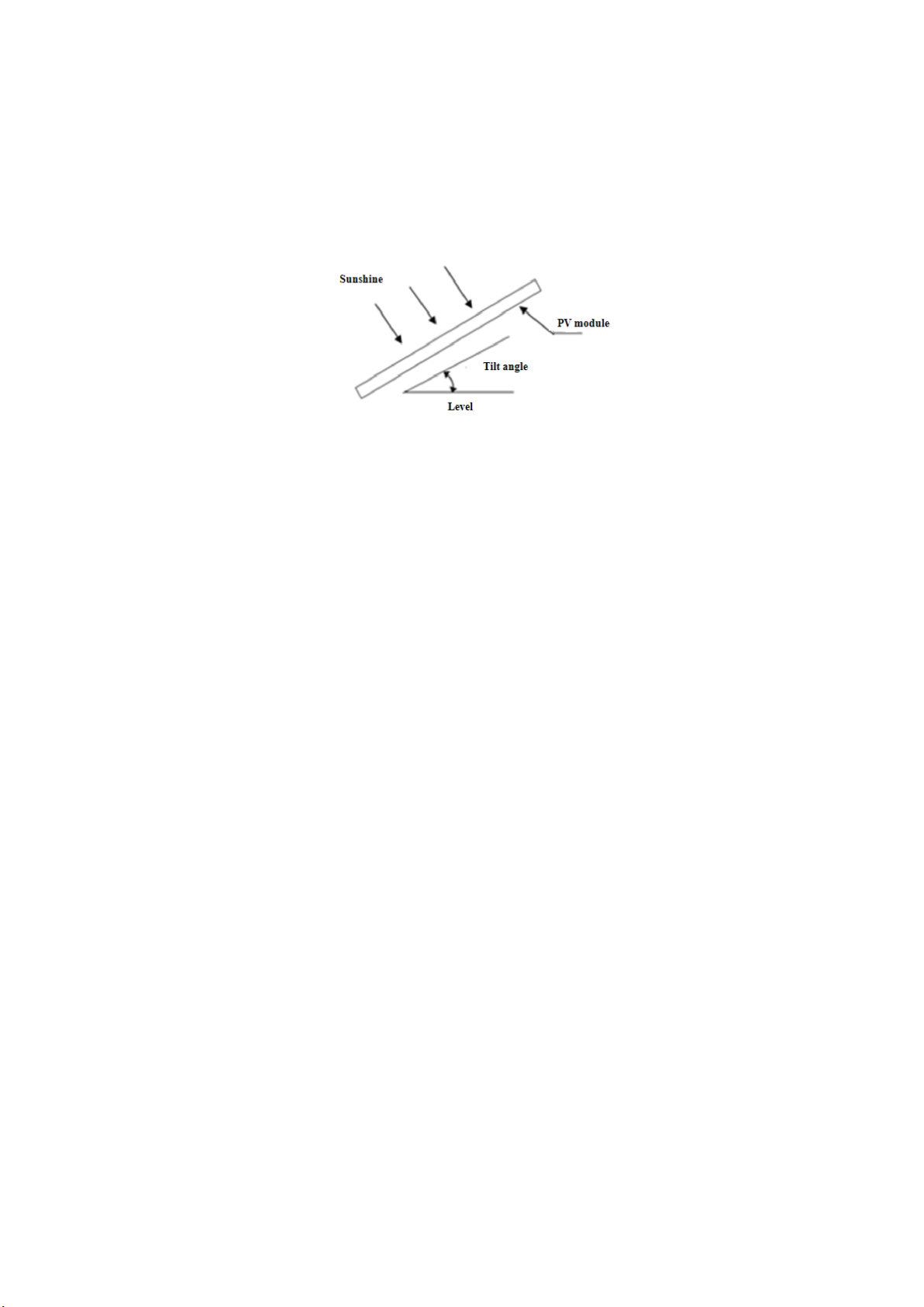
5.3 Tilt angle selection
5.3.1 The tilt angle of the Modules is measured between the surface of the modules and a horizontal ground
surface, the modules generates maximum power output when it faces the sun directly, as shown in figure 2.
5.3.2 Modules each element in series with the same array must be oriented in the same direction and angle.
Different installation directions and angles will cause the modules to absorb the total solar radiation difference,
causing the loss of output power, thus reducing the operating efficiency of the system.
5.3.3 The maximum power is generated when the sun is directed to the module, select the best installation angle
should be considered when the winter module power output. But external or otherwise artificially concentrated
sunlight shall not be directed onto the front or back face of the PV module.
ECO Shingled V2.1
8/ 16
5.3.4 In order to facilitate the cleaning modules and modules in the rain when the surface dust is easily washed
away by rain. For detailed installation angles, follow the advice given by the experienced PV module installer.
Figure 2 Module tilt angle
6. Mechanical installation
All of the installation methods described here are for reference only. Eco Delta Power Co., Ltd is not
responsible for providing the relevant installation parts and module installation services.
6.1 Conventional requirement
6.1.1 Ensure that the installed modules and supporting rail of modules are strong enough, the entire PV system
consisting of modules must be able to withstand anticipated mechanical pressure. The installer must provide the
guarantee. The installation supporting rail must be tested by the third-party organization with the analysis ability
of Static Mechanical according to the local national or international standards.
6.1.2 The supporting rail must be made of environmental corrosion, anti-rust and UV-resistant materials.
6.1.3 Modules must be securely fastened to the supporting rail.
6.1.4 Drilling holes on the surface of module glass or drilling additional mounting holes on module frames may
void the warranty.
6.1.5 Forces generated during thermal expansion and contraction of the supporting rail may influence the
performance and use of the module, so make ensure that the minimum distance between two neighboring frames
is 10mm, but in order to ensure good ventilation. Suggest this distance between two neighboring frames is 30mm.
6.1.6 In areas with large snow cover in winter, select a higher mounting bracket so that the lowest point of the
module will not be covered by snow for long periods of time. In addition, the lowest point of the module is high
enough to prevent the module from being obstructed by vegetation or trees.
6.1.7 The bearing surface of the supporting system must be smooth without any twist or deformation, and all of
them shall be at the same height without dislocation.
6.1.8 The module mounting method does not result in electrochemical corrosion between the aluminum frame of
the module and the different metals.
6.2 Three kinds of Mounting
6.2.1 Roof mounting
6.2.1.1 It is necessary to provide a special supporting rail for the roof mounting. When installing a module on a
roof or building, ensure that it is securely fastened and cannot fall or be damaged as a result of strong winds or
heavy snow. During roof mounting, check the building codes being used to ensure that the building and its
structure where the module is installed have adequate bearing and sealing capacity. The roof when penetrated
ECO Shingled V2.1
9/ 16
during module installation shall be properly sealed to avoid rainwater leakage.
6.2.1.2 To be suitable for operation, reduce steam condensation and facilitate the ventilation & heat dissipation of
the module during tile installation, the module shall be parallel to the wall or roof surface of the building, and the
distance between module and surface of the wall or roof shall be at least 50mm to prevent wiring damage and to
allow air circulation, ventilation and heat dissipation behind the module. For stacking type installation, the module
shall be installed on the fire-resistant roof. The Fire Resistance Rated Class of the modules is Class C, and the
modules are suitable for mounting on an above Class A roof. Do not install modules on a roof or building during
strong wind.
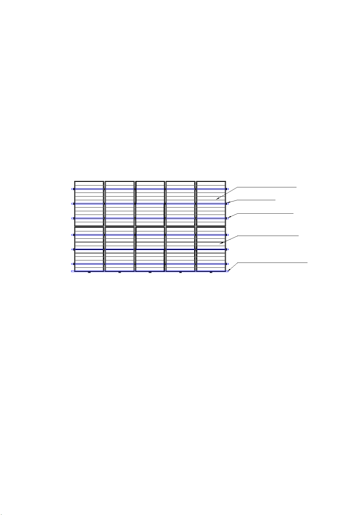
6.2.1.3 For the roof system installed in the area with relatively heavy snowfall or snow cover in the
meteorological records, the installer shall reinforce the supporting system at the lower frame of the module, in
order to prevent the lower frame from being pressed and damaged by the falling snow or freezing of the melt ed
snow. Eco Delta suggests selecting the support reinforcing mechanism shown in figure 3.
Figure 3 Schematic diagram of reinforcement mounting of module
6.2.2 Pole mounting
When installing a module on a pole, choose a pole and supporting rail that will withstand the anticipated
wind power of the local area. The pole must be constructed on a solid foundation.
6.2.3 Ground mounting
Select the height of the mounting system to prevent the lowest edge of the module from being covered by
snow for a long time in winter in areas with heavy snowfalls. The module shall be installed on the supporting rail
with appropriate height instead of being directly laid on the ground. In addition, the lowest portion of the module
shall be high enough (≥900 mm) from ground, so that it is not shaded by plants and trees, or damaged by sand and
stone driven by wind, or not shaded by the mud splashed by rain water.
6.3 Installation methods
6.3.1 General rules
a) Modules can be fastened on the supporting system using screw bolts or clamps. Modules must be installed
according to the following methods or instructions. If not the warranty may be void.
b) Eco Delta modules have reached the IEC standard on the mechanical load requirements. When mounting,
fasten the screws through the 4 or 6 symmetrical mounting holes on the inside of the aluminum bezel or use
the pressure clamp to secure the module to the supporting rail, Eco Delta module can withstand the wind
pressure of 2400Pa and the snow pressure of 5400Pa (Only the module models covered in this manual are
available), it is recommended that the system designer or installer perform the load calculations.
The clamp
The upper module
The support rail
The under module
The strength support
ECO Shingled V2.1
10 / 16
c) The supporting rail and other materials required (such as screw) shall be made of durable, resistance to
environmental corrosion, anti-rust and UV-resistant materials.
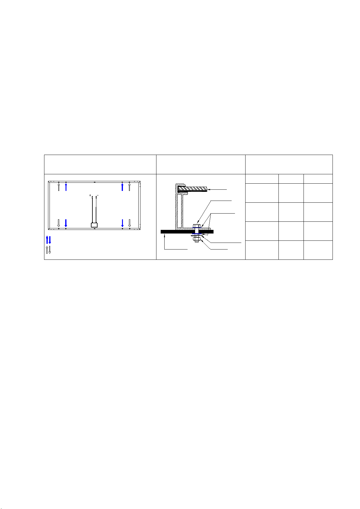
6.3.2 Screw installation
6.3.2.1 Use anti-corrosion M8 bolts to fix through the mounting holes on the module frame. Each module needs to
be fixed on 4 or 8 mounting holes, as shown in Table 1 Schematic diagram of mounting holes for fixed modules.
If you need to strengthen the installation, it is recommended to use the 6.3.3 fixture installation method.
6.3.2.2 When fixing with M8 bolts, spring washers and flat washers must be added to 4 or 8 symmetrical
mounting holes. See Table 1 for bolt fixing diagrams. The recommended torque for tightening screws is 16N·m .
The recommended accessories are shown in Table1:
Table 1 Bolt fixing assembly
Mounting holes location Screw bolts fasten method Recommend accessories
Module
M8 Screw
Flat washer
Spring washer
M8 Nut
The Support
rail
Part name material dimension
screw
Stainless
steel
M8×
16mm
spring
washer
Stainless
steel
M8
flat washer
Stainless
steel
M8
Nut
Stainless
steel
M8
6.3.3 Fixture installation
6.3.3.1 Use a certain number of clamps to fix the modules on the mounting bracket. Eco Delta recommends that
the clamps be clamped on the long frame of the module. The area of the A side of the module frame held by each
fixed clamp is not less than 400mm²(clamp length: ≥50mm, The width of the contact between the fixture and
the A surface of the frame: 9~11mm).
6.3.3.2 When installing the fixing jig, do not touch the front glass, and do not scratch or deform the aluminum
frame during installation. At the same time, the jig cannot affect the normal operation of the module. Make sure
that the drain hole and ground hole are not blocked during installation.
6.3.3.3 Each module needs to be fixed with at least four fixtures, and each long frame is equipped with at least
two fixtures. According to the local application conditions (actual conditions of wind and snow), additional
fixtures may be required to ensure modules and systems are subjected to corresponding loads. Fixtures with the
following conditions are recommended (as shown in Figure 4) or approved by the module system installer.
Under low wind pressure and snow load conditions,
these mounting holes should be used.
Under high wind pressure and snow load conditions,
these mounting holes must also be used.

ECO Shingled V2.1
11 / 16
The support rail
Clamp B
Clamp A
Fixture A: Fixture for edge module Fixture B: Fixture for intermediate modules
For the 35*35 frame, the recommended value of X is 34mm For the 35*35 frame, the recommended value of X is 25mm
For the 40*35 frame, the recommended value of X is 39mm For the 40*35 frame, the recommended value of X is 30mm
Figure 4 Assembly fixture installation method
6.3.3.4 When clamping the fixture to the frame of the module, use spring washers, flat washers and bolts to fix the
module on the mounting frame. Note that both ends should be clamped in a symmetrical position in the center.
M8 bolts and matching The screw is fixed, and the torque of the screw is 8N·m.
6.3.3.5 If there is large snowfall or snow pressure in the module installation area and large wind pressure, it is
recommended that the customer adopt a 5400Pa reinforced installation solution to clamp the fixed module (as
shown in Table 2 recommendations) to increase the front of the module Resistant to static snow pressure and
dynamic wind pressure on the back, improving the system's pressure resistance.

ECO Shingled V2.1
12 / 16
Table 2 The clamping range of the fixture
Note:
A: Length of this type of module.
B: Width of this type of module.
C: The distance of clamp center1 from the edge of this type of module.
D: The distance of clamp center 2 from the edge of this type of module.
E: Clamped width of the module frame by the clamp of this type of
module.
F: Clamped length of the module frame by the clamp of this type of
module.
* Note: Eco Delta limited warranty will be void in cases where improper clamps or installation methods deviating
from this manual are used. When using clamps to fasten the modules, pay attention to the following requirements:
(a) Take care of the module frames, not to twist or deform them.
(b) Avoid the clamps’ shading influence the module.
(c) Not to damage the surface of module frame.
(d) Make sure that the module's drainage holes not be plugged.
Module Type Installation
method mechanical load /Pa A/mm B/mm C/mm D/mm E/mm F/mm
ECO-xxxM-72S Long side
Installation
positive3600、negtive1600 1942 1069 390±50 /
9~11 ≥50
positive5400、negtive2400 1942 1069 390±50 970±50
ECO-xxxM-72SA Long side
Installation
positive3600、negtive1600 1969 1084 395±50 /
9~11 ≥50
positive5400、negtive2400 1969 1084 395±50 985±50
ECO-xxxM-78SA Long side
Installation
positive3600、negtive1600 1969 1140 395±50 /
9~11 ≥50
positive5400、negtive2400 1969 1140 395±50 985±50
ECO-xxxM-72SB Long side
Installation
positive3600、negtive1600 2056 1140 410±50 /
9~11 ≥50
positive5400、negtive2400 2056 1140 410±50 1028±50
ECO-xxxM-60S Long side
Installation positive5400、negtive2400 1622 1068 325±50 / 9~11 ≥50
ECO-xxxM-60SA Long side
Installation positive5400、negtive2400 1646 1084 330±50 / 9~11 ≥50
ECO-xxxM-66SA Long side
Installation positive5400、negtive2400 1646 1140 330±50 / 9~11 ≥50
ECO-xxxM-60SB Long side
Installation positive5400、negtive2400 1719 1140 345±50 / 9~11 ≥50
6.3.2.6 For matters concerning clamp or installation not mentioned in this manual, contact the local dealer for
professional support.

ECO Shingled V2.1
13 / 16
7. Electrical installation
7.1 Electrical property
7.1.1 Under normal conditions, a photovoltaic module is likely to experience conditions that produce more current
and voltage than reported at standard test conditions. Accordingly, the values of ISC and VOC marked on this
module should be multiplied by a factor of 1.25 when determining module voltage ratings, conductor current
ratings, fuse sizes, and size of controls connected to the PV output.
7.1.2 Try to use the modules with the same configuration in the same PV system. If the modules are connected in
series, the total voltage is the sum of voltages of all the modules. The maximum voltage of string does not exceed
the maximum system voltage of the modules (the maximum system voltage of Eco Delta modules is 1500V), the
maximum number of modules that can be connected in a series string must be calculated in accordance with
applicable regulations, make sure the open circuit voltage of string does not exceed the maximum system voltage
of the modules and the other electrical DC modules required at the minimum temperature at the PV system
location. Using the following formula:
System voltage=N*Voc*[1+λvoc (Tmin - 25℃)]
N——number of modules in series
Vo c ——open circuit voltage at STC (refer to product label or data sheet)
λvoc——Thermal coefficient of Voc of each module (refer to product data sheet)
Tmin——minimum ambient temperature at the PV system location
7.1.3 If the PV system requires the installation of high current, several PV modules can be connected in parallel,
and total current is the sum of current of all the modules. The maximum parallel number of the modules N= Imax
(fuse rating) /Isc.
7.1.4 An over-current protection device with appropriately rated must be used when reverse current could exceed
the value of the maximum fuse rating of the module, an over-current protection devices is required for each series
string if more than two series strings are connected in parallel.
7.1.5 When installing the module, place the end with the junction box up and try to avoid the rain.
7.1.6 Do not carry out installation in rainy weather, because humidity will void the insulation protection, Thus
cause safety accidents.
7.2 Cables and wiring
7.2.1 Use a junction box with a degree of protection IP67 or above. The junction box has a connected cable and
connector. Each module has two single-conductor wires, one positive and one negative, which are pre-wired
inside the junction box. Installers can connect two modules by firmly inserting the positive connector of a module
into the negative connector of the other module. Refer to the following table for details of junction box.
7.2.2 Never perform pretreatment to modules including connector, junction box and cable with lubricating oil or
cleaning agent made of alkanet materials during installation.
7.2.3 The cross section area of the cable and connector capacity selected must satisfy the maximum short-circuit
current of the system (It is recommended that the cross section area of the cable used for the single module is
4mm2, Please note that the temperature limit range of the cable is -40℃~+90℃).
7.2.4 When fastening the cables to the supporting rail, pay attention to avoid mechanical damage to the cables or
modules, and also making a special design to protect the cables from environmental corrosion and direct sunshine,
for example, put the cable into the supporting beam or special pipes with UV-resistant materials. The cables
designed are sunlight resistant and waterproof, but also to avoid direct sunlight exposure and water immersion of
the cables.
7.3 Connectors

ECO Shingled V2.1
14 / 16
7.3.1 When connecting modules, make sure that the connectors of the same series module shall come from the
same manufacturer or totally be compatible with each others, and the same requirements shall go to the
connection terminals of series string and PV system, because the connectors from different manufacturers may not
be compatible with each others, which easily leads to mismatch risk.
7.3.2 Ensure that connector caps are tightened before connecting the modules, keep connectors dry and clean. Do
not attempt to make an electrical connection when the connectors are wet, soiled, or otherwise faulty conditions.
Avoid sunlight exposure and water immersion of the connectors.
7.4 Bypass diodes
The junction box of the Eco Delta module contains bypass diode and forms a parallel structure with the solar cell
circuit. When the solar cell sheet is blocked or damaged, a hot spot phenomenon occurs locally in the module, and
the diode will operate so that the current is no longer discharged from the hot spot solar cell flow, thereby limiting
module heat and performance loss. Please note that bypass diodes are not overcurrent protection devices.
7.5 Grounding
7.5.1 Modules use anodized aluminum alloy frame as a rigid support, in order to avoid modules by lightning and
electrostatic damage, as well as the protection of personal safety, all module frames and mounting racks must be
grounded. If there is no special provision, please follow the International Electrotechnical Commission standards
or other international standards. Use the recommended connection terminals to connect the grounding cable to the
module frame. Use 12 AWG copper wire for the grounding wire. As shown in Figure 5 on the module ground
hole and its label, Figure 6 shows the module grounding method.
Aluminum frame
Grounding hole
Grounding label
Figure 5 Grounding hole and ground label Figure 6 Grounding method
7.5.2 The frames have pre-drilled grounding holes and brand with signs, these holes should be only used for
grounding purposes, but not for mounting the modules. And do not drill any additional grounding holes on the
frames of the module, which may void the warranty.
7.5.3 For optimum power output, it is recommended to ground the DC negative pole of the module array.
7.5.4 The grounding cables must be fully contact with inside of the aluminum alloy, and the connection terminal
must penetrate the oxidation coating of frame during grounding. Connecting the module frames and supporting
beams using suitable grounding conductors can achieve good grounding. If the supporting system is made of
metal, the surface must be electroplated and have excellent conductivity.
7.5.5 The grounding cables must be connected to the earth through a suitable grounding electrode. Recommend to
use the grounding accessories (lugs) to connect the cables. Welding grounding cable to the jack of lugs, then
inserting M4 screws into the ring of the lugs and the grounding holes of module frames, fastening with M4 nuts.
Spring washers should be used to prevent the screws from loosening and lead to poor grounding.
7.5.6 If the module is used in high-temperature and high-humidity environment, Eco Delta suggest the customer
M4 Nut
Grounding cable
Aluminum frame
Tooth washer
Flat washer
Cup washer
M4 Screw
ECO Shingled V2.1
15 / 16
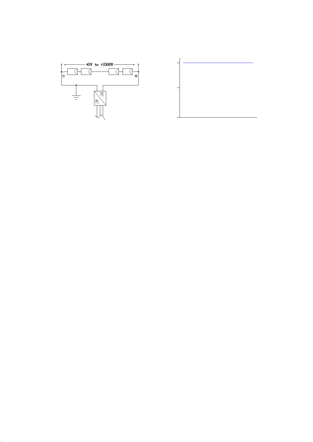
configure the inverter which allows negative grounding and contains isolation transformer (as shown in figure 7).
Figure 7 Schematic diagram for grounding potential of the inverter
7.5.7 Eco Delta modules may be grounded using a third-party earthing device, provided that the earthing must be
reliable. The earthing device is operated in accordance with the manufacturer's requirements.
8. Maintenance and care
Modules need to be inspected and maintained regularly, especially during the warranty period. To ensure
optimum performance of the modules, the following maintenance measures are recommended.
8.1 Cleaning
When modules are working, there should not be environmental influence factors to cover shadows in the
modules, such as other modules, supporting rail, plants, large number of dust etc., which may directly reduce the
power output and may even cause regional hot–spot effect. Therefore clean the glass surface on a regular basis,
clean modules take measures so as:
a) The frequency of the cleaning module depends on the rate of dirt buildup. Under normal conditions, the rain
will clean the surface of the module, but it is still need to regularly use a soft sponge or cloth (dry or wet)
cleaning modules. Any situation cannot use of rough surface materials to clean modules, no use of acid and
alkali cleaner to remove dirt.
b) Avoid pressing part of the module hard during cleaning, which may cause glass deformation, cell damage
and reduction of the module’s life.
c) Remove the snow covered on the module in time to avoid the module damage caused by long-term
accumulation of snow cover and freezing of melted snow.
d) when cleaning the negtive of the module needs to avoid piercing negtive-sheet.
e) It is recommended that modules be cleaned in the early morning or late afternoon when light is low and the
module temperature is low, especially for areas with high temperatures.
f) Do not attempt to clean modules that are damaged by glass or have exposed electrical wiring, which may be
subject to an electric shock hazard.
8.2 Visual inspection
Please carefully check the modules of the existence of visual defects, focusing on the following items:
a) Check whether the module glass is broken.
b) Check if the front of the module is obstructed by obstacles or foreign objects.
c) Check the module negtive-sheet whether there is hot, negtive film raised, burn through the traces and so on.
d) Check whether the cell bus–bar is corroded, whether encapsulation materials of the module has delamination,
bubbles, etc.
+1500
+750
+0
With negative Grounding
Voltoge of string to ground/V

ECO Shingled V2.1
16 / 16
e) Check the tightness of the bolts and the electrical connections at the connection points between the modules
and the supporting rail.
8.3 Inspection of connector and cable
It is advisable to carry out a preventive check every 6 months and check the following:
a) Check Junction box adhesive for cracks or cracks.
b) Check the connector interface sealing and whether there is loose, melt deformation, aging or corrode.
c) Check that the cable connections are secure and that the modules are properly grounded.
When module is found to be defective, consult a qualified service technician. If servicing is required, it should
be serviced by a qualified service technician. Module exposure generates high voltages in the sun, so cover the
modules with opaque material when servicing modules to prevent electrical shock.
Note:
1. if found in the maintenance of any problems, feednegtive to the professional service personnel for
confirmation;
2. If using maintenance and repair measures not included in this manual, consult your local dealer for
professional support.
9. Disclaimer of liability
9.1 Because the use of the manual and the conditions or methods of installation, operation, use and maintenance
of photovoltaic (PV) product are beyond Eco Delta’s control, Eco Delta does not accept responsibility and
expressly disclaims liability for loss, damage, or expense arising out of or in any way connected with such
installation, operation, use or maintenance.
9.2 Eco Delta shall not be liable for damage to the product resulting from the installation or the design of the
power generation system.
9.3 No responsibility is assumed by Eco Delta for any infringement of patents or other rights of third parties,
which may result from ues of the PV product, No license is granted by implication or otherwise under any patent
or patent rights.
9.4 In the installation of modules, the customer is not in accordance with the requirements of the listed this
manual operation, tong wei does not provide any warranty.
9.5 The information in this manual is based on Eco Delta’s knowledge and experience and is believed to be
reliable, but such information including product specification (without limitations) and suggestions do not
constitute a warranty, expresses or implied.
9.6 Eco Delta reserve the right to change the manual, module technical specification, nameplate or product
information sheets without prior notice.
ECO DELTA POWER CO.,LTD
Office:No.65 Dangcang Road,Zhonglou,Changzhou,China
Website: www.ecodeltapower.com
Email: [email protected]
This manual suits for next models
8
Table of contents
Popular Control Unit manuals by other brands

System Sensor
System Sensor M500M Installation and maintenance instructions

Carrier
Carrier Signature Series Installation sheet

Thermo Scientific
Thermo Scientific Orion Versa Star instruction sheet

APARIAN
APARIAN Cell Connect A-CELL quick start guide

K-Team
K-Team KoreUSBCam user manual

Azbil
Azbil ACTIVAL VY54X0F Series Specifications & instructions


National Instruments
National Instruments PXIe-5693 CALIBRATION PROCEDURE

Sangoma
Sangoma EXP100 quick start guide

Richter
Richter KN Series Installation and operating manual

Genebre
Genebre V Series Installation, operation and maintenance manual

Dewetron
Dewetron DAQP-LA Series Technical reference manual

SMC Networks
SMC Networks JSXD Series Operation manual