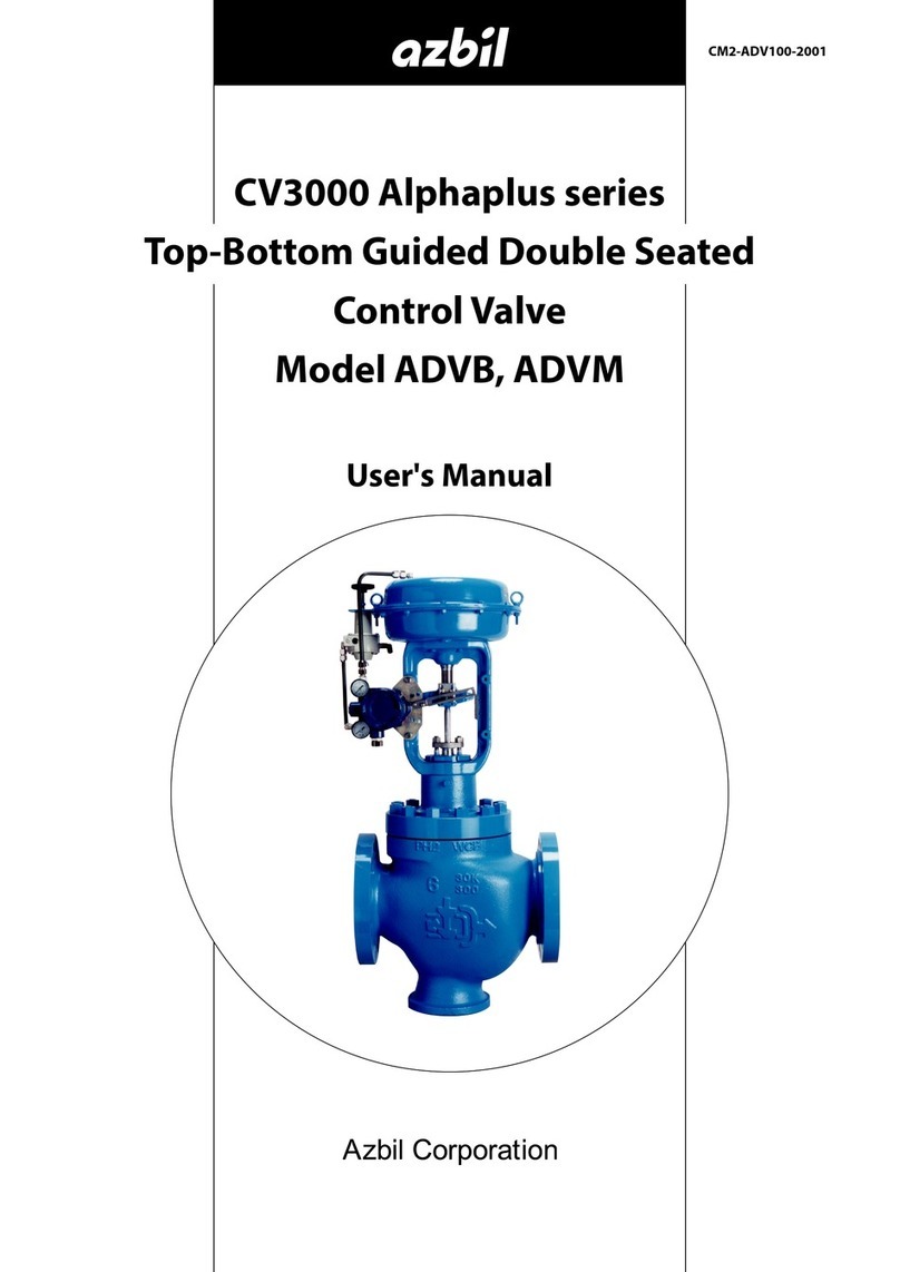
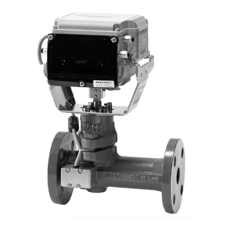
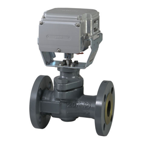
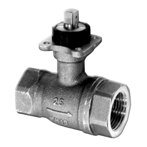
Azbil ACTIVAL VY54X0F Series User manual
Other Azbil Control Unit manuals

Azbil
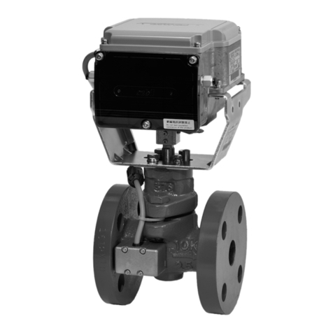
Azbil NX-CB1 User manual
Azbil
Azbil ACTIVAL+ Intelligent Component Series User manual

Azbil
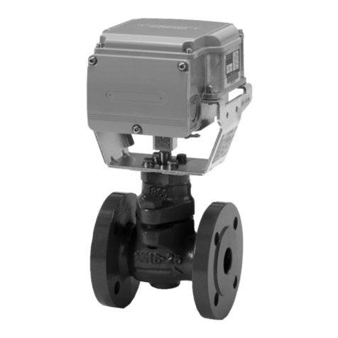
Azbil ACTIVAL PN16 User manual
Azbil
Azbil Actival VY51 J Series User manual

Azbil
Azbil CV3000 Series User manual

Azbil
Azbil Actival VY51 J Series User manual
Azbil
Azbil ACTIVAL VY5302A Series User manual
Azbil
Azbil ACP Series User manual
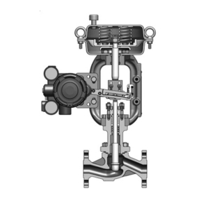
Azbil
Azbil AGVB User manual
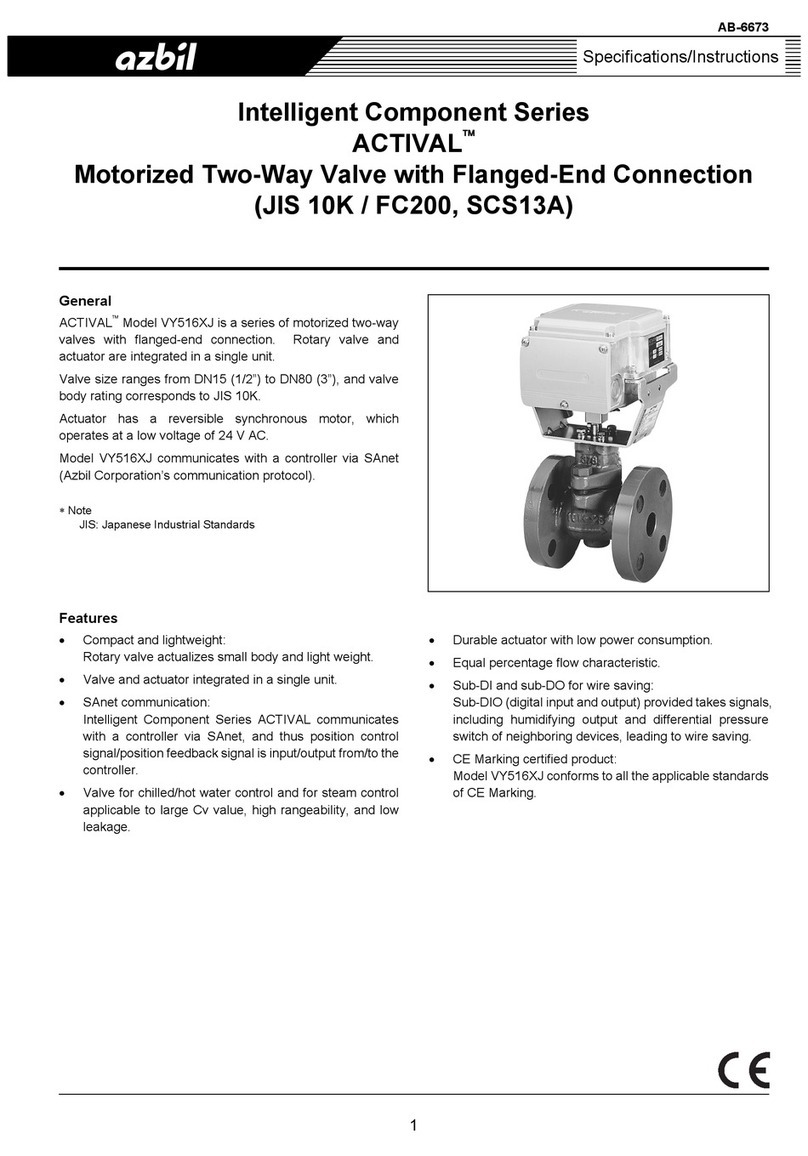
Azbil
Azbil ACTIVAL VY516XJ Series User manual
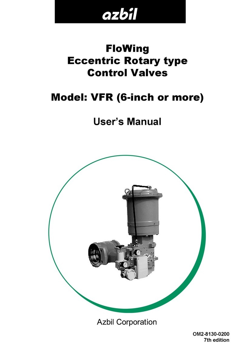
Azbil
Azbil FloWing VFR User manual

Azbil
Azbil ACTIVAL Intelligent Component Series User manual
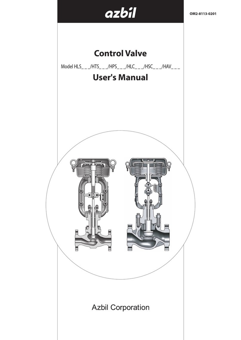
Azbil
Azbil HLS Series User manual
Azbil
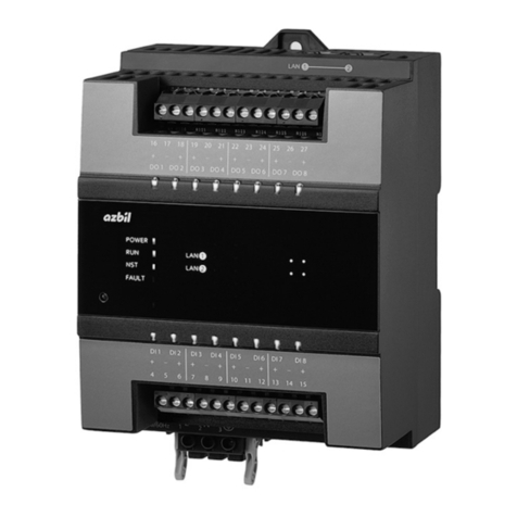
Azbil VDC User manual
Azbil
Azbil RJ-1 Series User manual
Azbil
Azbil VY63 Series User manual
Azbil
Azbil NX-D15 User manual
Azbil
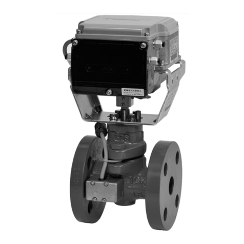
Azbil ACTIVAL FVY5130J User manual
Azbil
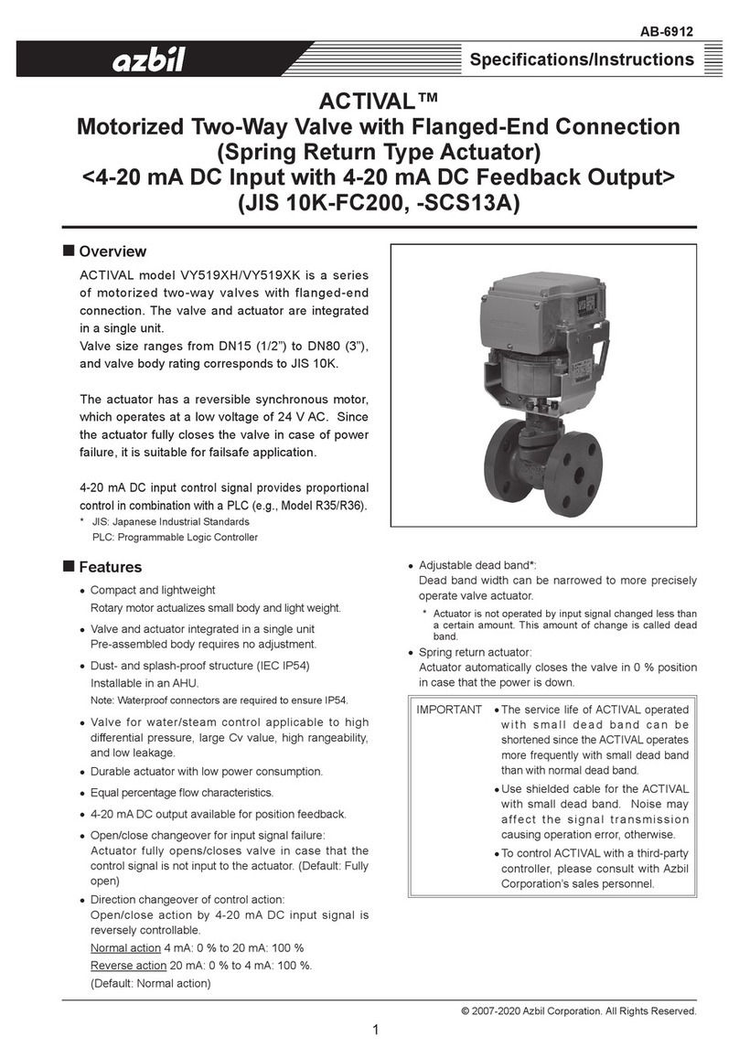
Azbil ACTIVAL VY519XH User manual
Azbil
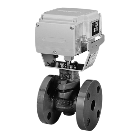
Azbil ACTIVAL VY519 J Series User manual
Popular Control Unit manuals by other brands

Festo
Festo Compact Performance CP-FB6-E Brief description

Elo TouchSystems
Elo TouchSystems DMS-SA19P-EXTME Quick installation guide

JS Automation
JS Automation MPC3034A user manual

JAUDT
JAUDT SW GII 6406 Series Translation of the original operating instructions

Spektrum
Spektrum Air Module System manual

BOC Edwards
BOC Edwards Q Series instruction manual

KHADAS
KHADAS BT Magic quick start

Etherma
Etherma eNEXHO-IL Assembly and operating instructions

PMFoundations
PMFoundations Attenuverter Assembly guide

GEA
GEA VARIVENT Operating instruction

Walther Systemtechnik
Walther Systemtechnik VMS-05 Assembly instructions

Altronix
Altronix LINQ8PD Installation and programming manual
