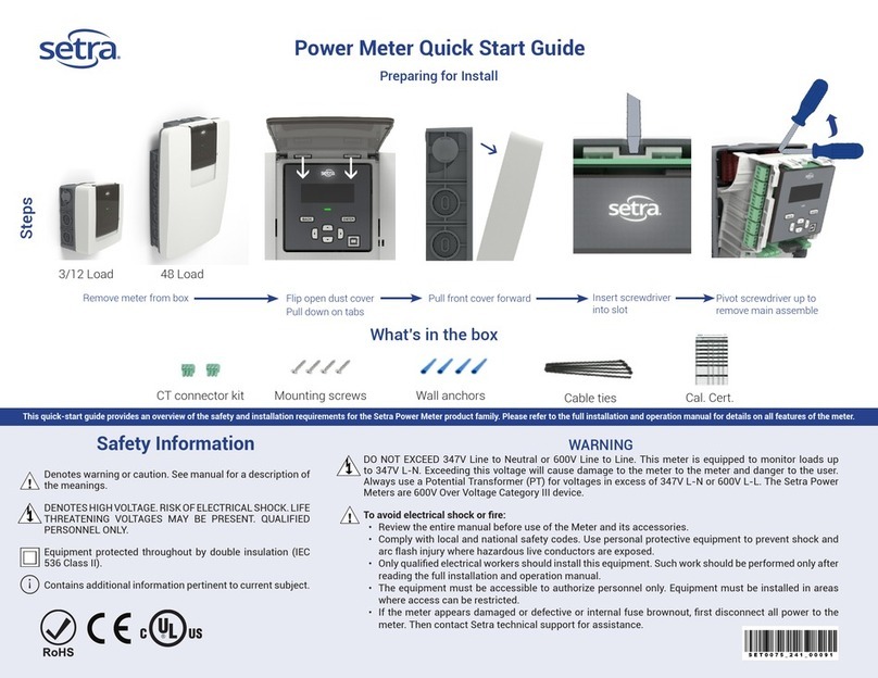
Eco-Eye Smart 3pA Series Installation manual

Smart 3pA Page 1
Eco-Eye Smart Commercial
Smart 3pA
3 phase monitoring and recording
Set-up and Operating
Instructions
Efficient technology for today’s world
eco-eye
real-time electricity monitors

Smart 3pA Page 2
Contents
1. Introduction
1.1 Package contents
1.2 Important notes
2. Installing Eco-eye Smart Commercial
2.1 Overview
2.2 Find your Electricity supply
2.3 Attaching the sensors
2.4 Connecting to the transmitter
2.5 Powering the display
2.6 Is it working
3. Using the Display
3.1 Real-time or Predicted Mode
3.2 Accumulator
3.3 History – How many Kilowatts used
4. Change Settings
4.1 Calibrating the temperature
4.2 Changing the radio channel
4.3 Checking the signal strength
5. Guide to the screen
6. IMPORTANT – Safety and Care
7. Guarantee
See the document “Smart3p operating guide” for details of how to
use the memory card and optional USB cable

Smart 3pA Page 3
Introduction
The Smart 3pA monitors are sophisticated devices designed especially for commercial 3 phase
monitoring .
This monitor combines the simplicity of the Eco-eye brand but has some clever features which are
useful to anyone with commercial premises which they would like to monitor in detail and get a better
idea of their electricity usage and cost, it also has the benefit a large uncluttered screen
The unit itself allows the user to look at each phase individually (for checking phase balance) or
combined phases for training staff to be aware of their energy usage.
Also allows the user to look at how many Amps each phase is drawing and also look at the total that
is being drawn.
The Smart 3pA is a complete monitoring system for commercial premises and has the ability to log
all the information you’re seeing on the display to an MMC card and using our free computer program
can be converted into cost and analysed in more detail over different time periods
Package contents:
3pA-13 3pA-17 3pA-24 3pA-36
Smart Monitor 1 1 1 1
Smart Transmitter 1 1 1 1
13 mm diameter sensors 3
17.5 x 22.4 mm sensors 3
24mm sensors 3
36mm sensors 3
C batteries for monitor 2 2 2 2
AA batteries for transmitter 2 2 2 2
Eco-eye memory card 1 1 1 1
USB cable Option Option Option Option
Instructions 1 1
Important Notes
●Do not insert the memory card until you have successfully got the monitor working and
displaying the correct values
●Do not insert the memory card unless the correct date and time have been set on the monitor.
●Press and hold the square button on the transmitter when powering up to get 3 phase mode.
●Always get the latest version of the computer software from eco-eye,com.

Smart 3pA Page 4
2.1. Overview
Eco Eye Smart has three basic components – The sensors, the transmitter and the Wireless
display.
The sensors clip round the three live cables under your meter or fuse box (as illustrated above
1,2,3) and monitors the total current passing through them.
This is a simple job and involves no cutting or disturbing of any wiring or the need for a qualified
electrician unless you feel uncomfortable removing electrical trunking to get access to cables. If
you’re not happy installing this product please consult a qualified electrician!
Once the sensors are fitted to the cables they simply plug into the transmitter and the data is then
sent wirelessly to the display.

Smart 3pA Page 5
2.2 Locating your meter
Once you have located your electricity meter it should look something like the one listed
below.
You will need to connect the 3 sensors round the 3 live cables coming into that meter. The
sensors simply clip round each of the coloured cables – Red, Yellow and blue. (The black is the
neutral)
In the picture below there are 2 cables for each phase, generally the left hand one is from the grid
and the right one is the supply to the property. It is best to use the right cable as the left one is the
property of the supply company

Smart 3pA Page 6
2.3 Attaching the sensors
The Sensor is in two parts and one is clipped around each of the three live cables.
Press the side clips of the sensor to separate the two parts.
Place it around the cable.
Click shut- do not force the sensor shut around a cable that is too big as
this could damage the sensors inner core.
If the sensor will not easily fit round the cables you’re trying to monitor then you may be trying to
attach it to an armoured or multi core cable.
The faces of the sensor must make a flat contact.
The sensors are designed to be a loose fit around the cables.
Use the live cable tester if you’re in doubt as to the whether you’re connected to
the live cables.
Fit the tester to the end of the sensor – the LED will illuminate if the cable being
monitored is live.
Remember to remove this tester before continuing set up.
The sensor may buzz, if not connected to the transmitter.

Smart 3pA Page 7
2.4 Connecting the sensors to the transmitter
Plug the three sensor cables into the transmitter on the underside of the transmitter. Remembering
which cable is plugged into each socket.
(I.e. sensor 1 = Red etc.)
Press the release catch to remove the wall plate and use a double sided self-adhesive sticky pad
or screw (not supplied) to affix in a convenient position close to the cables being monitored.
Make sure the release catch in on the left hand side.
Fit 2 x AA Batteries into the transmitter making sure they are the right way round (see below)
Press and hold the square button on the transmitter while installing
the batteries to set it to 3 phase transmit mode
Once you have inserted the batteries you
should see the red light start to flash on
the Eco eye transmitter.
Clip the back onto the transmitter and
plug the sensors into the bottom of the
transmitter.

Smart 3pA Page 8
2.5 Power up the display unit
Remove the battery cover from the display unit (and the memory card if installed) and insert 2 x C
Cell batteries, ensuring they are in the right way round.
Then replace the battery cover
After a short power up routine you will need to input some basic information.
Set the currency using the < and > Arrows select £,$,€ or
Then press the right hand green button to store
Set the Date (Year, Month, Day) using the < and > arrows.
Press the green button bottom right to save and move on.
Set the time in hours and minutes using the <and > arrows.
Press the green button bottom right to store.
Note:
Selecting the currency also inputs the most appropriate country specific value for voltage
2.6 Is it working?
If the sensor and transmitter are connected correctly, the display will automatically show the current
KW reading for the total of all 3 phases (if all 3 are plugged in) and one of the LEDs on the display
will be flashing at the same time as the LED on the transmitter every 4 seconds.
Try switching your Kettle on or a high energy piece of machinery and you should see the big number
increase and at this point you will notice the red light begin to flash on the monitor.
Remember the transmitter talks to the display by radio so check that you have the antenna icon
visible in the bottom right hand corner of the display,

Smart 3pA Page 9
3. Using the display
The main use of the buttons is as follows:
Round Green button changes the units
●Kilowatts
●Amps
●Clock, calendar and temperature
Rectangular green button
●In Kilowatts and amps:
●Real-time display
●Accumulator
●In Clock:
●Day
●Month
●Year
●Temperature
Square red button (in Kilowatts and Amps)
●Total
●Phase 1
●Phase 2
●Phase 3
3.1 Real-time or Predicted Mode
Eco-eye Smart normally shows how much electricity you are using right now. This is real-time or
predicted mode. You will see the arrow and P (see left) when you are in predicted mode.
7 days history is stored on the monitor and can be accessed in Amps and Kilowatts by pressing
the left arrow key. The icon will change to H
Press the green rectangular button to return to real-time display.
3.2 Accumulator.
Smart has an accumulator feature built in so you can see the totals of each phase separately and
see if one phase is using more than another over a given time period of 1 day.
To activate this function you just press the rectangular green button on KW or Amps and “hour” in
the top right will change to a calculator symbol on the bottom of the display. This tells you it is
accumulative consumption so far today.

Smart 3pA Page 10
4.1 Changing the Voltage on the display
The Kilowatt value is calculated from the amps being monitored by reference to a voltage stored on
the monitor.
To change the stored voltage value:
Use the round green button to the KW display
press and hold the rectangular green button 3 seconds and Volts “SET” will appear.
This voltage is the phase to neutral value so will normally be about 240 for the U.K.
Using the < and > arrows alter this to the desired setting
Press the rectangular green button to confirm this and return to normal operation
4.2 Changing the Transmitter channel
There are 30 channels available and the transmitter and monitor can be set to any of these when
multiple units are near each other or there are problems with interference from other equipment.
●Start by bringing the display and the transmitter close together and remove the batteries from
the transmitter
●With the batteries out, press and hold the round green button on the front of the transmitter
nearest the LED’s Holding the button, now put the batteries in and keep holding the button and
you will see a solid green LED illuminates on the transmitter.
●Lift your finger off the button and press it 6 times for channel 6 etc. you have 30 channels on
the transmitter.
●Once you have pressed the button for the amount of channels you require, wait and the green
LED will start to flash and you need to count the flashes to make sure it flashes for example 6
times f you selected channel 6 and then there will be a slight pause and it will continue with its
regular 4 second flashes.
●Reset to 3 phase mode by removing a battery and holding the square button on the transmitter
while inserting the battery.
●Next we need to set he display to the same channel.
●On the Display go to Amps and then press and hold the rectangular green button until “SET”
and CH 02 is displayed. (CH 02 is the default channel)
●Press the rectangular green button to select the channel.
●On the display you should now have what looks to be a radio mast in the bottom right hand
corner. Within 10 seconds one the the monitor LEDS should start flashing at the same time as
the LED on the transmitter
You can check the transmitter channel at any time by simply removing the batteries from the
transmitter and re-inserting them whilst looking and counting the flashes of the LED on the front of
the transmitter. (for example you will get 6 flashes very quickly then a slight pause and one flash
to confirm then it will resume its four second cycle as normal.
Do not forget to hold the square button down when replacing the transmitter battery to get
back to 3 phase transmit mode.
4.3 Checking the signal strength
Use the round green button to display time.
Press the red square button on the left of the display and a number will appear and begin to move
between -30 and + 30 (+30 being very good and -30 very bad) your monitor should be between
-15 to +30 in order to be able to write to the card in full sections otherwise you may find you lose
data if your signal is intermittent.
Don’t forget to screw the antenna on the back of your smart display if you find the monitor
is having problems with signal.

Smart 3pA Page 11
5. Guide to the screen
A. The Big Number
B. Modes
C.Time Periods
D.Target graph
E. Real-time (predicted) display
F. History display
G.Used during firmware upgrade
H. Low battery indicator
I. Used when setting Voltage
J. Good radio reception
K. See Trax manual
L. See Trax manual
M. See Trax manual
N. Big number is accumulated
O. Big number is target %
P. Overflow, used when big number
goes over 9999
Some icons are not used in this version of Smart but are on the screen ready for
planned upgrades.

Smart 3pA Page 12
6. IMPORTANT - Safety and Care
1.Before attempting to fit Eco-eye, ensure you have read and understood the fitting instructions
fully.
2.Do not attempt to carry out any repairs to Eco-eye. Contact your retailer or Eco-eye direct if
problems occur.
3.Use of Eco-eye near moisture or liquids; or in extreme temperatures can cause malfunction
and damage.
4.Take care when handling and disposing of batteries. They can cause burns to skin or property if
in contact with heat, conductive or corrosive materials. Remove batteries when storing Eco-eye
for long periods to avoid corrosion.
5.The LCD screen is glass and should be treated carefully to avoid scratches. Should it become
damaged, it may leak crystals which could be harmful to your health. Dispose of with great care.
6.Eco-eye should only be cleaned using a damp cloth. – Under no circumstance should any
chemicals or cleaning agents be used.
7.Do not subject Eco-eye to any form of impact or shock.
8. IF IN ANY DOUBT regarding the installation of this product, consult a qualified
electrician before proceeding.
7. Guarantee
This Eco-eye product is guaranteed for the period of one year from the date of purchase
against defects in respect of both material and workmanship.
HOWEVER, this warranty does not apply to normal wear and tear and does not cover any
parts damaged by misuse or neglect in any way, or by modifications made by any person other
than those working for Eco-eye.
This guaranteed does not cover cracks or scratches to the screen under any circumstance, nor
shall Eco-eye be held liable for any direct, indirect, incidental, special or consequential loss or
damages whatsoever caused by the use of Eco-eye even if advised of the possibilities of such
damages.
In order to validate this guarantee, please ensure you keep your original receipt and read all
instructions carefully.
Eco-eye Smart
conforms to quality standards: CE, PB, RoHS, amendment
2004/108/EC, EN55 022
Class B and EN 55 024 RTTE, 89/336/EEC. Eco-eye
The Modern Moulds Business Centre,
Commerce Way, Lancing,
West Sussex,
BN15 8TA.
Email: info@eco-eye.com
Website: www.eco-eye.com
This manual suits for next models
4
Table of contents
Other Eco-Eye Measuring Instrument manuals
Popular Measuring Instrument manuals by other brands
FRER
FRER QUBO Q72P3H Series operating manual
PCB Piezotronics
PCB Piezotronics IMI Sensors Platinum Swiveler 607A11-0023 Installation and operating manual
AMPLITUDE
AMPLITUDE Magma 200 Quick troubleshooting guide

UEi
UEi C091 instruction manual
Sperry instruments
Sperry instruments DSAG00TRMS operating instructions
Agilent Technologies
Agilent Technologies 8970B operating manual

