Eco House Comfort FHZ1000 User manual

FHZ1000 House Control Unit
FHT 8W Heat Demand Relay
Installation and User Guide
Product Code EHC-FH06
1
Product Code EHC-FH01
13
- Attach the second half, as shown in figure 7.
Figure 7
- Engage the plug that you have prepared in the wall holder
as shown in figure 8.
Figure 8
- Plug the power supply into a proper socket (230V~/50Hz).
- Slide the control centre onto the wall holder from above.
See figure 9.
Figure 9
- If you purchased the economy set (set comprising FHZ1000 and valve operating mechanism), this is how you now
install the valve operating mechanism.
- If you purchased the FHZ1000 individually, what you do next depends on the available components (if necessary,
install the valve operating mechanism, etc., or register the available heating controls with the FHZ1000).
FHT 8W Heat Demand Relay
Installation and User Guide
Product Code EHC-FH06
1

2
Introduction
Dear customer,
Thank you for purchasing this product.
This product meets the requirements of both current national and European guidelines.
In order to ensure continued fulfilment of legal requirements and safe operation of this product, we kindly ask you to carefully
follow the instructions in this user manual!
All company and product names contained herein are trademarks of their respective owners. All rights reserved.
Should you have any further questions, please contact our technical service:
Germany: Tel. no.: +49 9604 / 40 88 80
Fax. no.: +49 9604 / 40 88 48
Mon. to Thur. 8.00am to 4.30pm
Fri. 8.00am to 2.00pm
FHT 8W Heat Demand Relay
Installation and User Guide
Product Code EHC-FH06
1

FHT 8W Heat Demand Relay
Installation and User Guide
Product Code EHC-FH06
1

3
Table of contents
Page
1. Prescribed use ............................................................................................................................................................ 6
2. Scope of delivery ....................................................................................................................................................... 6
3. Safety instructions ..................................................................................................................................................... 6
4. System description .................................................................................................................................................... 7
a) ‘FHZ1000’ radio control centre ............................................................................................................................. 7
b) FHT8b room control/heating control ..................................................................................................................... 8
c) FHT8V valve operating mechanism ..................................................................................................................... 9
d) FS20 TS telephone remote control ...................................................................................................................... 9
e) HMS/FHZ alarm dialler .......................................................................................................................................... 9
f) FS20 components ................................................................................................................................................. 9
5. Installing the FHZ1000 system............................................................................................................................... 10
a) Mounting the FHZ1000 control centre ............................................................................................................... 10
1. Suitable installation location ......................................................................................................................... 10
2. Inserting the 9V block battery, setting the date and time ........................................................................... 10
3. Installing the FHZ1000 or mounting it to a wall ........................................................................................... 12
b) Mounting the FHT8V valve operating mechanism ............................................................................................ 14
1. Removing the old thermostat ....................................................................................................................... 14
2. Inserting the batteries into the valve operating mechanism ....................................................................... 14
3. Mounting the valve operating mechanism ................................................................................................... 15
c) Setting up the radio connection between the control centre and the room control ......................................... 17
1. Operating principle ........................................................................................................................................ 17
2. Necessary preparations ............................................................................................................................... 17
3. Registering the room control ........................................................................................................................ 17
4. Deleting room controls .................................................................................................................................. 19
d) Registering and managing the components of the wireless control system .................................................... 20
1. The house code ............................................................................................................................................ 20
2. Setting the house code ................................................................................................................................. 20
3. Address system ............................................................................................................................................. 21
4. Managing the addresses .............................................................................................................................. 22
5. Example of an address assignment ............................................................................................................. 23
6. Registering (adding) the remote switching components ............................................................................ 24
7. Deleting remote switching components ....................................................................................................... 26
8. Programming (associating) the remote switches or remote dimmers ....................................................... 26
6. Operating the system .............................................................................................................................................. 28
a) Operating structure basics .................................................................................................................................. 28
1. Display and controls of the FHZ1000 .......................................................................................................... 28
2. Operating/menu structure of the FHZ1000 ................................................................................................. 28
3. Setting the display’s contrast ....................................................................................................................... 30
4. Setting the back light .................................................................................................................................... 31
5. Button lock ..................................................................................................................................................... 31
FHT 8W Heat Demand Relay
Installation and User Guide
Product Code EHC-FH06
1

4
Page
b) Programming the heating settings ...................................................................................................................... 32
1. Operating modes .......................................................................................................................................... 32
2. Setting the comfort temperature and the lowering temperature ................................................................ 33
3. Configuring the week profile ......................................................................................................................... 34
4. Switching between comfort and lowering temperature ............................................................................... 35
5. Heating pause ............................................................................................................................................... 35
6. Closing the valve ........................................................................................................................................... 35
7. Changing the name of a room controller ..................................................................................................... 35
8. Changing the security code of a room controller ........................................................................................ 36
c) Programming the remote switching components .............................................................................................. 37
1. Changing the name of a remote switching component .............................................................................. 37
2. Changing the address of a remote switching component .......................................................................... 37
3. Operating modes .......................................................................................................................................... 38
4. Programming the switching times ................................................................................................................ 40
5. Manually switching a remote component on and off .................................................................................. 41
d) Working with macros ........................................................................................................................................... 42
1. Activating a macro ........................................................................................................................................ 42
2. Entering the name of the macro ................................................................................................................... 42
3. Programming or editing a macro .................................................................................................................. 43
3a) Room controller and control centre ....................................................................................................... 43
3b) Remote switching components .............................................................................................................. 46
e) Status indicator .................................................................................................................................................... 48
f) Alarms ................................................................................................................................................................. 48
1. Alarm triggers/alarm priorities ...................................................................................................................... 48
2. Alarm confirmation (alarm dialler, = HMS/FHZ radio telephone dialler) .................................................... 50
3. Low temperature alarm ................................................................................................................................. 51
7. Special internal functions ....................................................................................................................................... 53
a) Setting the time for the decalcification cycle, ‘CALC’ ........................................................................................ 53
b) Selecting the temperature unit to be displayed, ‘°C°F’ ..................................................................................... 54
c) Setting the date and time, ‘DAT’ ......................................................................................................................... 54
d) Setting the security code, ‘CODE’ ...................................................................................................................... 54
e) Setting the number of valve operating mechanisms, ‘no H’ .............................................................................. 55
f) Synchronising the valve operating mechanism, ‘SYNC’ ................................................................................... 56
g) Test function, ‘TEST’ ........................................................................................................................................... 56
h) Displaying the valve position, ‘STEL’ ................................................................................................................. 57
i) Setting the valve operating mechanism offset, ‘OFFS’ ..................................................................................... 57
j) Setting the minimum temperature for the low temperature alarm, ‘t-AL’ .......................................................... 57
FHT 8W Heat Demand Relay
Installation and User Guide
Product Code EHC-FH06
1

5
Page
8. ‘FS20 TS’ telephone remote control ..................................................................................................................... 58
9. ‘HMS/FHZ’ radio telephone dialler (alarm dialler) ............................................................................................... 59
a) Registering the alarm dialler with the FHZ1000 ................................................................................................ 59
1. Alarm dialler settings .................................................................................................................................... 59
2. Entering the telephone numbers 1 to 3 ....................................................................................................... 60
3. Entering the dialout number ......................................................................................................................... 60
4. Entering the alarm dialler’s PIN, for remote control over a telephone ....................................................... 61
5. Allow remote control (yes/no), number of call signs before automatic call acceptance ........................... 62
6. Carrying out a test alarm .............................................................................................................................. 62
b) Alarm dialler’s alarm calls .................................................................................................................................... 63
c) Remote control of the FHZ1000 via the alarm dialler ........................................................................................ 63
10. Emergency operation of the valve operating mechanism ................................................................................ 64
11. Replacing the batteries ........................................................................................................................................... 65
a) Control centre ...................................................................................................................................................... 65
b) Valve operating mechanism ................................................................................................................................65
12. Battery and environmental tips ............................................................................................................................. 66
13. Troubleshooting ....................................................................................................................................................... 67
a) Control centre ...................................................................................................................................................... 67
b) Valve operating mechanism ................................................................................................................................68
14. Radio transmission interference ........................................................................................................................... 69
15. Handling ................................................................................................................................................................. 69
16. Maintenance and cleaning ...................................................................................................................................... 69
17. Disposal ................................................................................................................................................................. 70
a) General information ............................................................................................................................................. 70
b) Batteries and rechargeable batteries ................................................................................................................. 70
18. Declaration of conformity (DOC) ........................................................................................................................... 70
19. Appendix A, code table ........................................................................................................................................... 71
20. Appendix B, character set for the FHZ1000......................................................................................................... 72
FHT 8W Heat Demand Relay
Installation and User Guide
Product Code EHC-FH06
1
6
1. Prescribed use
The FHZ1000 is the central element of a heating control system that can control individual heating controls (type FHT8b)
and valve operating mechanisms (type FHT8V).
In addition, remote switching components belonging to the system can be controlled (FS20 wireless control system).
Please also read the detailed description in ‘4. System description’.
2. Scope of delivery
• FHZ1000
• Wall mounting set (screws & dowels)
• Power supply for FHZ1000
• Valve operating mechanism with valve adapters (only with the economy set, item no. 617500!)
• User manual
3. Safety instructions
The product’s guarantee becomes invalid if the product is damaged as a result of failure to
observe these operating instructions. We do not assume any liability for any resulting
damages!
Nor do we assume liability for damage to property or personal injury caused by improper use
or failure to observe the safety instructions. In such cases the product’s guarantee becomes
invalid!
Do not use this product in hospitals or medical institutions. Although the product emits only relatively weak radio signals,
these may cause life-support systems to malfunction. This may also be the case in other areas.
The product is only suitable for use in dry indoor rooms.
For safety and licensing (CE) reasons any unauthorised alterations to and/or modification of the product are not permitted.
Do not leave packaging material lying around. This may become a dangerous plaything in the hands of children.
The product is designed in accordance with protection class II. Only a proper socket (230V~/50Hz) from the public power
supply system may be used as a voltage source for the power supply.
The product is not a toy and should be kept out of the reach of children.
Do not expose the device to direct sunlight, intense heat, cold, moisture or dampness.
Handle the product with care; knocks, blows or even a fall from a low height can damage it.
FHT 8W Heat Demand Relay
Installation and User Guide
Product Code EHC-FH06
1

7
4. System description
Today, there are many reasons why we should give some thought to efficient energy consumption.
High oil and gas prices are surely the most important of these reasons, however, the desire to use non-renewable resources
responsibly and the need to reduce the strain on the environment are also crucial factors.
We also need to rethink our normal day-to-day requirements. Because of work commitments heating is rarely required all
day long in one and two-person households.
The high demands placed on a heating control system as a result of flexible working times, irregular absence, and so on
can barely be managed by a conventional control system. Modern energy management is required, which guarantees the
efficient use of energy along with the benefits of convenience.
Warmth and comfort should always (and only then) be available as they are required.
The FHZ1000 radio control system fulfils these requirements in an exemplary way and can also enhance comfort and
individual feel-good factor.
The available system components of the heating control system are described briefly below.
a) ‘FHZ1000’ radio control centre
The FHZ1000 radio control centre is the central element of the heating control system, which manages individual room
controls (for example, the FHT8b heating control) and individual valve operating mechanisms (for example, the FHT8V) as
well as the remote switching components of the FS20 wireless control system.
Furthermore, heating can be remotely controlled via the control centre (using room controls/valve operating mechanisms)
and problems with the heating system can be read from the control centre itself and also received by telephone/mobile
phone.
Using the room control (FHT8b heating control), the room temperature can be individually controlled for up to 15 rooms.
The control centre communicates with the individual room controls, which in turn adjust the temperature locally (that is, in
the corresponding rooms) via the valve operating mechanisms.
All settings for the rooms can be conveniently carried out on the control centre and are then remotely transmitted to the
individual room controls. Of course, changes made directly at the location (on the room control itself) are also transmitted
to the control centre (only possible with the FHT8b heating control).
The FHZ1000 itself can control the room temperature in the room in which it is installed; no additional FHT8b
room control/heating control is required in this room.
Its functions include:
• Control of the room temperature with separate day and night programs for each day of the week
• Up to 8 radiators can be controlled in one room
• Holiday/party function for temporary temperature alteration
• Weekly limescale protection function prevents seizing of the valve
• Antifreeze function
System failures and unforeseen circumstances, such as extreme temperature variations, which point to a malfunction of
the heating system, are visually and acoustically indicated by the control centre.
When you are not at home, the optionally available alarm dialler (HMS/FHZ radio telephone dialler) can also automatically
send a message to you; to your mobile phone, for example. Particularly in the winter, this can prevent costly damages from
arising (frost damage) while you are not at home.
In addition to controlling radiators via the valve operating mechanisms and FHT8b heating control, the FHZ1000 can also
control up to 15 components from the FS20 wireless control system.
FHT 8W Heat Demand Relay
Installation and User Guide
Product Code EHC-FH06
1

8
Lamps, awnings, blinds, domestic appliances and so on can all be conveniently switched on and off via the
FHZ1000. Depending on your personal requirements, these can be automatically timed, you can press a
button or use a telephone.
This way, security can be increased considerably through presence simulation, for example (the pro-
grammed switching on and off of various lights in a house).
Different scenarios can be represented using 4 freely programmable macros (a macro refers to a series of several functions/
commands that are carried out one after the other):
• Adjust all living rooms to the lowering temperature with just one press of a button
• Roll out the awning in the winter garden
• Switch on a ventilation system
• Switch lamps on and off
Here you can assign a plaintext name (10 characters) for each device and each macro.
With the help of the FS20TS telephone remote control or the HMS/FHZ radio telephone dialler (neither are included in the
delivery, but are available separately!), you can send these commands while you are on the move from your mobile phone
or from your office.
You can, for instance, heat up your bath or switch on your outside lights while still driving home in your car.
Despite its wide range of functions, the clearly structured operator prompts and large, illuminated display, amongst other
things, ensure that the system is easy to use.
The exchange of data between the FHZ1000 and the room controls (FHT8b required) and the telephone dialler takes place
over an exceptionally secure bi-directional radio connection in the 868 MHz frequency band.
Thanks to the legal restriction of transmission duration in this band to a maximum 36 seconds per hour (1% duty cycle),
the danger of interference from other radio services is minimised. Furthermore, an additional security code is used for the
data exchange.
A plug-in power supply (unit) and a 9V block battery is used for the power supply. The battery also serves to preserve data
when there is a power failure.
The control centre is suitable for wall mounting using the supplied wall holder and for installation.
b) FHT8b room control/heating control
The FHT8b is installed in the individual rooms and is connected by radio to the FHZ1000 control centre and the FHT8V valve
operating mechanism. The FHT8b measures the room temperature and compares this with the target temperature, which
is manually provided or provided by the time program.
The difference is used by the control algorithm to calculate how far the valve has to be opened or closed in order to achieve
the desired temperature.
The valve position is transmitted by radio to the valve operating mechanism that is mounted on the radiator. This valve
operating mechanism then reduces or increases the heat accordingly.
Alterations to the temperature settings or to the time program can be carried out locally or via the FHZ1000 control centre.
The continuous exchange of the latest adjustments between the room control and the control centre guarantees that both
units always have the same, up-to-date data. The room control periodically registers its status with the control centre, so
that the latter is kept constantly informed of any possible malfunctions.
No room control is supplied with the FHZ1000 or the economy set; they are available separately.
FHT 8W Heat Demand Relay
Installation and User Guide
Product Code EHC-FH06
1

9
c) FHT8V valve operating mechanism
The FHT8V valve operating mechanism replaces the existing thermostat. The draining of water, bleeding, etc., is not
necessary when mounting the valve operating mechanism.
The operating mechanism is powered by 2 AA batteries and is controlled by radio from the room control (FHT8b heating
control) or the control centre (FHZ1000).
This means that it is not necessary to lay any cables or provide a network connection.
A valve operating mechanism is supplied with the economy set (item no. 617500). Further valve operating
mechanisms for the FHZ1000 or the economy set are available individually.
d) FS20TS telephone remote control
Triggered by a telephone call, the telephone remote control enables the FHZ1000 to be remotely controlled.
Protected by a PIN, answer delay and house code, macro commands can be activated using any telecommunications
facility such as a landline, mobile telephone or the Internet etc. An analogue telephone connection or the option to connect
to a telephone system (analogue port for ISDN telephone systems) is required.
The connection to the telephone network is effected using a telephone connection cable with a TAE plug (F-encoded, like
a normal analogue telephone).
Remote control must be carried out using a touch-tone (DTMF) telephone or telephone system.
The FS20TS telephone remote control is not supplied with the FHZ1000 or the economy set but is available
separately.
e) HMS/FHZ radio telephone dialler (alarm dialler)
Activated by the control centre, the alarm dialler dials up to 3 different pre-programmed numbers (max. 22 digits), in order
to provide your mobile phone, office, or your appointed neighbours or friends during periods of absence, for example, with
information on the alarm trigger (tone signals).
As a result of the remote control, the alarm dialler can be positioned conveniently close to the telephone connection. All
operation is carried out from the control centre via menus.
Dialling, including getting an outside line for a telephone system is carried out fully automatically.
Macro commands can also be activated, as with the FS20TS (see item d), via the alarm dialler. An additional FS20TS
telephone remote control is then no longer required.
The alarm dialler is not supplied with the FHZ1000 or the economy set but is available separately.
f) FS20 components
The FHZ1000 can control components of the FS20 wireless control system. All remote switches (FS20ST, etc.) and remote
dimmers (FS20DI, etc.) can be operated. In the case of dimmers, please note that only on or off switching is possible;
dimming is not possible.
FS20 wireless control system components are available separately, and are not supplied with the FHZ1000
or the economy set.
FHT 8W Heat Demand Relay
Installation and User Guide
Product Code EHC-FH06
1

10
5. Installing the FHZ1000 system
Please note:
Please be sure to follow the steps in this order when installing the system:
1. Initial operation of the FHZ1000 control centre
2. Initial operation of the FHT8V valve operating mechanism(s) in the room in which the control centre is installed
3. Initial operation of the FHT8b room control/heating control in accordance with the relevant user manual
4. Registering the FHT8b room control/heating control with the FHZ1000
a) Mounting the FHZ1000 control centre
1. Suitable installation location
Power is supplied to the FHZ1000 via the supplied power supply unit. Please ensure that a socket is within the range of the
desired installation location.
The FHZ1000 is suitable for installation, as well as for wall mounting. For installation, a hinge is integrated on the back. In
this case the plug of the power supply that is included is connected directly to the FHZ1000’s socket.
For wall mounting, a wall holder is enclosed, which is set up to receive the power supply’s plug. The power supply is
established automatically when you slide the FHZ1000 onto the wall holder.
A 9V block battery must be inserted into the FHZ1000.
This serves not only for operation/control when there is a power outage, but also as a power supply when
you remove the FHZ1000 from the wall holder, for example, for the purposes of programming, operation or
control.
Please observe the following points when selecting the installation location.
The installation location should:
- occupy a central position in the room in which the temperature is to be controlled
- be easily accessible
- be at eye level
- not be on a poorly insulated exterior wall
- not be in direct sunlight
- not be on large metal objects
- not be exposed to parasitic induction from heat sources such as televisions, lamps, refrigerators, etc.
2. Inserting the 9V block battery, setting the date and time
Before any further installation work is carried out, you must first insert the 9V block battery. Please familiarise yourself with
how the control panel is arranged (see section 6. a) item 1).
Afterwards, proceed as follows:
• Open the battery compartment, by sliding the battery compartment cover on the back of the casing in the direction of
the arrow.
• Insert a 9V block battery, making sure that the polarity is correct. Observe the polarity diagram in the battery
compartment.
• Close the battery compartment again.
After a short display test (all segments are briefly visible), carry out the following settings. Do not take too much time when
carrying out the settings, otherwise the FHZ1000 will switch to the normal operating mode (if need be, remove the battery
again, reinsert it and carry out the settings again, or access the settings via the menu):
FHT 8W Heat Demand Relay
Installation and User Guide
Product Code EHC-FH06
1

11
• Setting the year:
Figure 1
By turning the scroller, you can change the year displayed. To confirm, briefly press the ‘PROG’ button once.
• Setting the month:
Figure 2
Select the desired month using the scroller and confirm by pressing the ‘PROG’ button again.
• Setting the day:
Figure 3
Use the scroller to set the day and confirm your setting by pressing the ‘PROG’ button.
• Setting the time (hours):
Figure 4
Use the scroller to set the hours and confirm your setting by pressing the ‘PROG’ button.
FHT 8W Heat Demand Relay
Installation and User Guide
Product Code EHC-FH06
1

12
• Setting the time (minutes):
Figure 5
The LCD then displays ‘Code’ and the four-digit security code, e.g., ‘1234’.
Make a note of the security code as you may need it again later.
In addition, ‘Auto’ and ‘120’ appear on the LCD. Afterwards, the control centre begins to count down from ‘120’ in steps
of 1 second and then returns to the normal operating mode.
The control centre automatically transmits the time to the room controls once every day. This means that if
the time needs to be corrected, you only need to change it on the control centre.
This can be done as described in section 7. c).
3. Installing the FHZ1000 or mounting it to a wall
• Installation
- Remove the wall holder from the back of the control centre by sliding it downwards.
- The power supply’s plug on the back of the casing is pushed from underneath into the FHZ1000.
- To install the device, open out the installation hinge on the back.
• Wall mounting
- Remove the wall holder from the back of the control centre by sliding it downwards.
- Hold the wall holder vertically on the wall with the rounded-off corners facing upwards.
- Mark the positions of the bore holes through the two slotted holes.
- Remove the wall holder and drill on the markings using a 6mm drill.
Be careful not to drill through any electricity lines, gas or water pipes!
- Insert the supplied dowels into the drill holes and mount the wall holder using the supplied screws.
- The next step is to mount the power supply’s barrel connector in the wall holder. For this purpose, a mounting sleeve
is provided with the control centre (2 halves), which is placed around the plug and then clicked into the wall holder.
- Insert the barrel connector into one half of the mounting
sleeve, as shown in figure 6.
Figure 6
FHT 8W Heat Demand Relay
Installation and User Guide
Product Code EHC-FH06
1

13
- Attach the second half, as shown in figure 7.
Figure 7
- Engage the plug that you have prepared in the wall holder
as shown in figure 8.
Figure 8
- Plug the power supply into a proper socket (230V~/50Hz).
- Slide the control centre onto the wall holder from above.
See figure 9.
Figure 9
- If you purchased the economy set (set comprising FHZ1000 and valve operating mechanism), this is how you now
install the valve operating mechanism.
- If you purchased the FHZ1000 individually, what you do next depends on the available components (if necessary,
install the valve operating mechanism, etc., or register the available heating controls with the FHZ1000).
FHT 8W Heat Demand Relay
Installation and User Guide
Product Code EHC-FH06
1
14
b) Mounting the FHT8V valve operating mechanism
Please note:
If no radiators are to be controlled in the room in which the control centre is installed, please skip the following
steps and continue with section c). Then switch off the control centre’s control function. Afterwards, the
control centre displays the current temperature measured in the room instead of the target temperature.
This is because the control centre should always be placed in the same room as the respective valve
operating mechanism, so that the room temperature can be controlled with the valve operating mechanism.
Otherwise, extreme temperature variations will result and the valve operating mechanism will be set
incorrectly. For example, the control centre measures 18°C in a living room and therefore turns the heating
up high. As the radiator is in another room, the control centre does notice the rising room temperature and
continues to turn up the radiator!
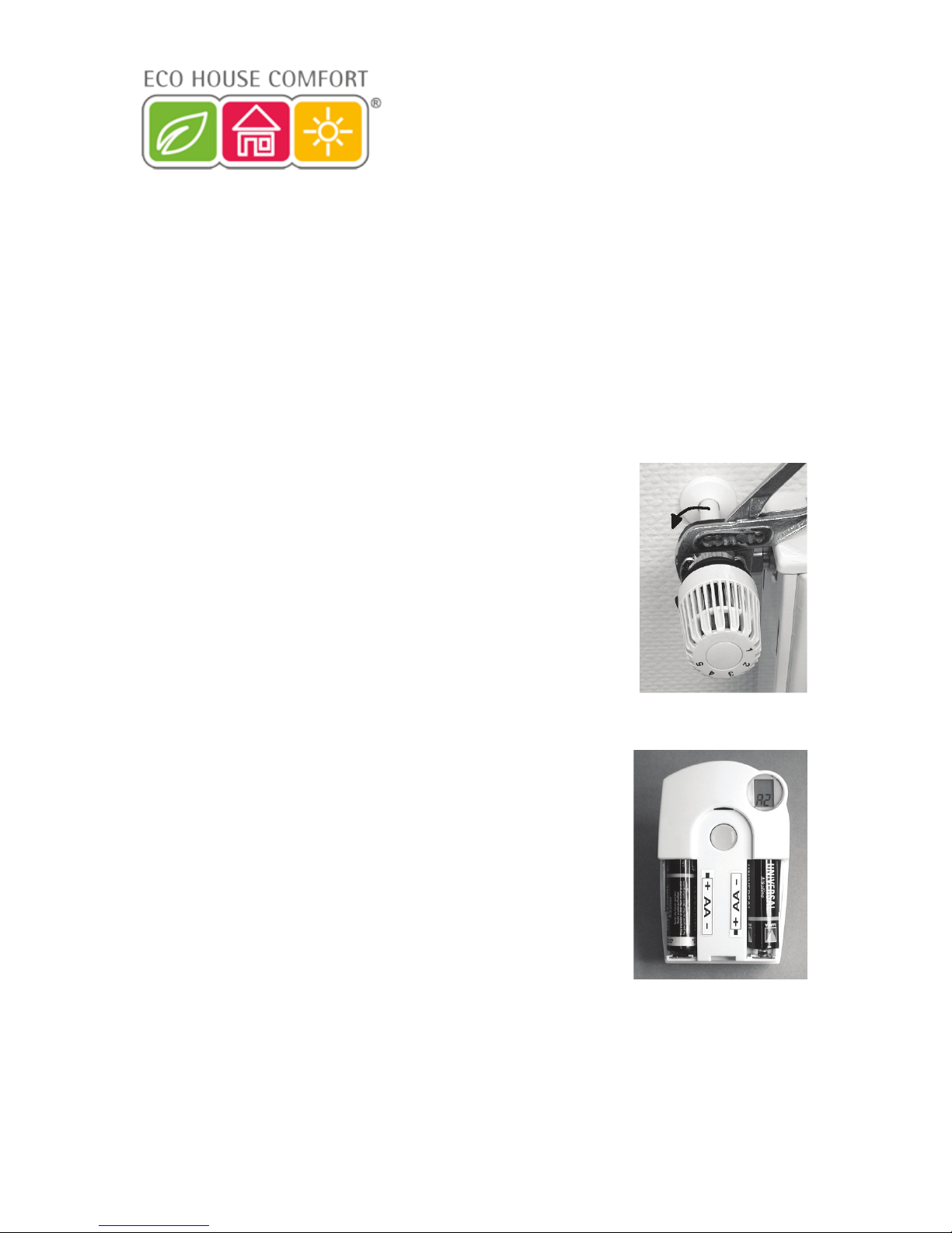
1. Removing the old thermostat
Remove the mechanical thermostat. If the screw connections have seized up you
can use multigrip pliers. Release the screw connection carefully by turning it
anticlockwise. See the arrow in figure 10.
Figure 10
2. Inserting the batteries into the valve operating mechanism
• Remove the battery compartment cover of the valve operating mechanism by
sliding it down and out.
• Insert two AA batteries (preferably alkaline) in the battery compartment,
observing the correct polarity. You will find corresponding figures in the
battery compartment.
Operation using rechargeable batteries is possible, but may result in short
operation times or reduced ranges. If you experience these problems, use
alkaline batteries, as described.
• ‘C1’ is displayed, followed by a two-digit number. ‘C2’ is then displayed,
followed by another two-digit number.
These two numbers are the two parts of the security code (e.g., ‘12’ and ‘34’
= security code ‘1234’).
• Afterwards a signal tone is emitted and ‘A1’ is displayed.
• The valve operating mechanism now fully retracts the control pin to facilitate
mounting.
• Afterwards ‘A2’ is displayed.
Figure 11
FHT 8W Heat Demand Relay
Installation and User Guide
Product Code EHC-FH06
1
15
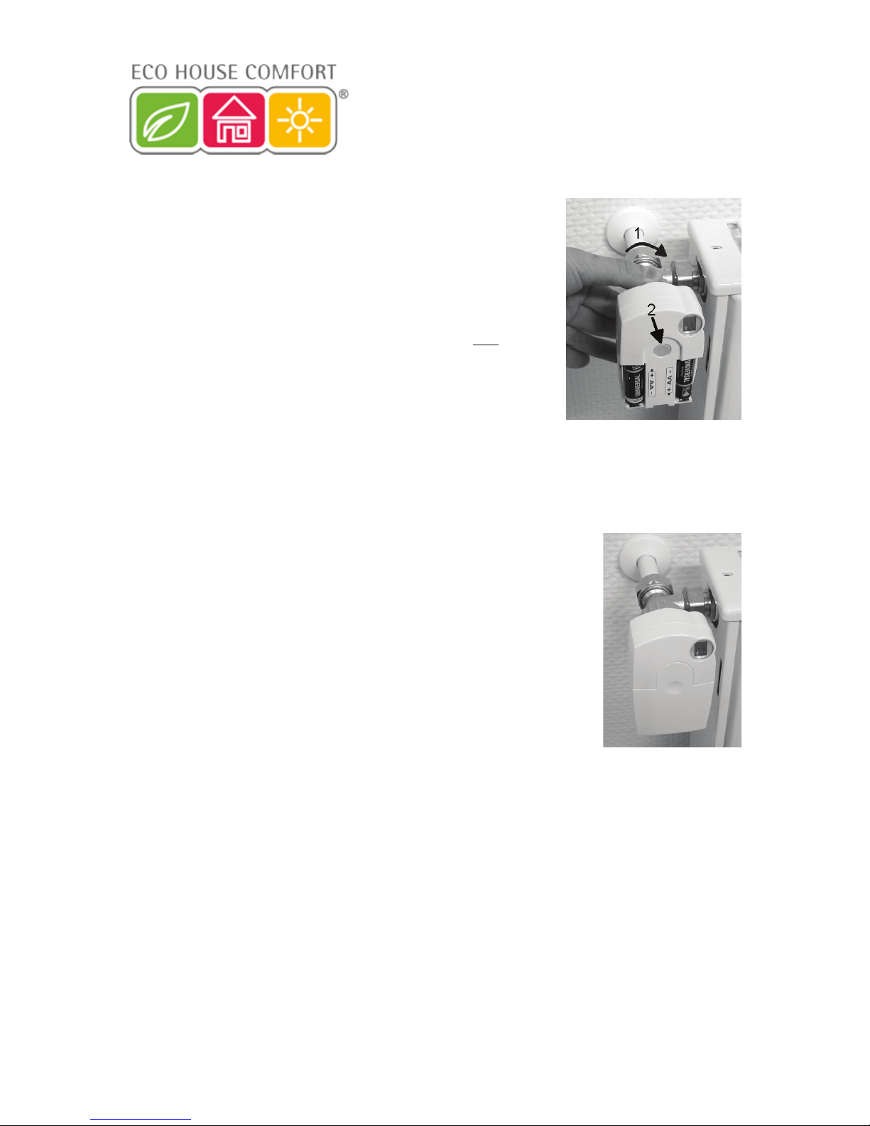
3. Mounting the valve operating mechanism
• Manually turn the coupling nut to fasten the valve operating mechanism to the
valve (‘1’ in the figure on the right).
On modern valves this can be done directly using a M30 x 1.5mm screw
thread. When using ‘Danfoss’ valves mount one of the enclosed adaptors to
the valve first.
The following figures 14, 15 and 16 show the adaptors that have to be used
for each valve.
• Briefly press the button ‘2’ on the valve operating mechanism once.
• ‘A3’ appears on the valve operating mechanism’s LCD and the valve is
closed.
• Afterwards, the antenna symbol blinks and ‘0%’ is displayed on the valve
operating mechanism’s LCD.
Please note:
If you purchased this valve operating mechanism separately and not as part of a set, such as the economy
set comprising the FHZ1000 and valve operating mechanism, for example, then the security code must now
be transmitted. This is described in detail in section 7. d).
• After the security code has been transmitted (not normally required for the
economy set), replace the battery compartment cover.
• The valve operating mechanism acknowledges receipt of the first wireless
protocol with a signal tone.
• The antenna symbol is now permanently displayed and the valve operating
mechanism now responds to radio commands from the FHZ1000.
This initially completes the installation for this room. The control centre works together with the valve operating
mechanisms that are mounted in this room with the factory-programmed settings.
The settings can be changed, as described in section 6. b).
Please note:
If you wish to mount further valve operating mechanisms, proceed as described above.
Afterwards, the number of radiators/valve operating mechanisms must be set on the control centre, as
described in section 7. e) (‘no H’ option), and the security code must be transmitted.
Figure 12
Figure 13
FHT 8W Heat Demand Relay
Installation and User Guide
Product Code EHC-FH06
1

16
Examples of ‘Danfoss’ adaptors:
Figure 14, type ‘RA’
Figure 15, type ‘RAV’
Figure 16, type ‘RAVL’
After attaching the adaptors for valves of the type ‘RAV’ and ‘RA’ to the valve body, the adaptors should be
fastened using the enclosed screw and nut.
For valves of the type ‘RAV’ you should also place the cylindrical extension piece onto the valve pin.
For later valve operating mechanism error signals, please see section 13.
There you will find information on troubleshooting and removing errors.
FHT 8W Heat Demand Relay
Installation and User Guide
Product Code EHC-FH06
1

17
c) Setting up the radio connection between the control centre and the room control
1. Operating principle
As with the radio connection between the room control and valve operating mechanism (or control centre and valve
operating mechanism), the radio connection between the control centre and the individual room controls is also provided
with a security code.
This serves to differentiate between the various room controls. So that the control centre and the respective
room control ‘understand’ each other, the room control must be registered with the control centre, that is, the
security codes are synchronised.
Transmission of the security code from the room control to the control centre takes place automatically.
The control centre’s receiver is permanently switched on and each room control sends its status along with the security
code in turn. The control centre creates an internal list of all the security codes it receives. This list can then be ‘browsed’
and the desired security codes can be confirmed. Then, the corresponding room control is registered with the control
centre and the radio connection is ensured.
When registering the room control, the following order must be observed:
• Switch on the control centre
• Switch on the valve operating mechanism which should form part of the control centre (for example, if you have
purchased the economy set or if you wish to register existing valve operating mechanisms directly with the control
centre)
• Switch on the room control (FHT8b) in accordance with its user manual
• Inspect the list of security codes received by the control centre and confirm (register) the desired room controls.
In order to ensure that the room control only cooperates with your control centre and not, for example, with
that of your neighbour’s, a room control can only be registered with a single control centre.
If registration is to be carried out on a different control centre, the room control must first be reactivated. You
can find a detailed description of this in the FHT8b room control’s user manual (special functions, ‘CEnt’)
2. Necessary preparations
The first two steps (switching on the control centre and valve operating mechanism) should already have been carried
out.
• Now switch on all the room controls, as described in the corresponding user manuals.
All the restarted room controls display the security code for radio communication with the control centre after
the batteries have been inserted. Make a note of this security code (for example, in the table in Appendix A
of this user manual) and alongside it write the name of the room in which the respective room control is
mounted (for example, Code 0606, bathroom).
• If you already have room controls that are switched on, remove the batteries and insert them again. Again, make a
note of the code as described before.
If a room control was already registered with a control centre, the room control must first be reactivated so
that it can be registered again. This is carried out as described in the room control’s user manual (special
functions, ‘CEnt’).
3. Registering the room control
For convenient programming from an armchair, for example, remove the control centre from the wall holder or remove
the power supply plug.
• Briefly press the ‘
’ button once.
• Select ‘Sonderfkt.’ (special function) using the scroller.
FHT 8W Heat Demand Relay
Installation and User Guide
Product Code EHC-FH06
1

18
• Briefly press the ‘
’ button once.
• Select ‘H-Regler’ (H controller) using the scroller.
• Briefly press the ‘
’ button once.
• Select ‘Hinzufügen’ (add) using the scroller.
• Briefly press the ‘
’ button once.
Afterwards, you can ‘browse’ through a list of the security codes of all the received room controls by turning
the scroller.
• Have the list of the security codes noted during the room control’s initial operation to hand (for example, table in
Appendix A) and select the security code by turning the scroller, for example ‘Code 0606’.
• Briefly press the ‘MAKRO’ button once.
By turning the scroller, you can now select from a list of pre-programmed room names.
The following room names are saved:
‘Arbeitsz.’ (work room), ‘Bad’ (bathroom), ‘Esszimmer’ (dining room), ‘Flur’ (hallway), ‘Gästez.’ (guest room), ‘Hobbyraum’
(hobby room), ‘Kinderz.’ (children’s room), ‘Küche’ (kitchen), ‘Schlafraum’ (bedroom), ‘WC’ (toilet), ‘Wohnzimmer’ (living
room).
If the desired room name is not there, select the room name which is most similar to the desired room name for the time
being.
This name can be changed later.
This can be done as follows:
• Use the scroller to select the room name concerned (for example, ‘Kinderz.’ = children’s room ).
• Confirm your selection by pressing the ‘MAKRO’ button.
• A cursor appears at the end of the LCD’s line (the blinking square is the cursor).
• If no changes are to be carried out, confirm the entry by pressing the ‘MAKRO’ button. The display briefly shows
‘gespeich.’ (saved).
• If changes are to be carried out, the cursor can be moved to the letter which is to be changed using the ‘
’ or
‘
’ button.
• The letter can be changed by turning the scroller.
• You can switch between upper and lower case, as well as special characters, by pressing the ‘ ’ button. The
character set can be found in Appendix B.
• Once you have entered the desired name, this must be saved.
To do this, press the ‘MAKRO’ button. The display briefly shows ‘gespeich.’ (saved).
• Afterwards, the FHZ1000 is in the ‘Regler’ (controller) menu and the display shows ‘Hinzufügen’ (add).
• Repeat the steps described above until you have registered all the noted rooms.
• If no further room controls are to be registered, press the ‘
’ button three times briefly, one after the other.
Afterwards, the FHZ1000 is in the normal operating mode again
FHT 8W Heat Demand Relay
Installation and User Guide
Product Code EHC-FH06
1

19
4. Deleting room controls
To delete a room control, proceed as follows:
• Briefly press the ‘
’ button once.
• Select ‘Sonderfkt.’ (special function) using the scroller.
• Briefly press the ‘
’ button once.
• Select ‘H-Regler’ (H controller) using the scroller.
• Briefly press the ‘
’ button once.
• Select ‘Löschen’ (delete) using the scroller.
• Briefly press the ‘
’ button once.
By turning the scroller, you can now browse through a list of the available room controls.
• Use the scroller to select the component to be deleted.
• Briefly press the ‘MAKRO’ button once.
• The display briefly shows ‘gelöscht’ (deleted).
• Afterwards, you are back in the ‘Regler’ (controller) menu.
• If further room controls are to be deleted, repeat the steps previously described.
• If no further room controls are to be deleted, press the ‘
’ button three times briefly, one after the other.
Afterwards, the FHZ1000 is in the normal operating mode again
Please note:
If the control centre itself is not to control any valve operating mechanism, the ‘internal control’ should be
deleted, as described above. To do this, use the scroller to select the ‘H 0 Intern’ ( H 0 internal) control and
delete it.
The control centre now displays the current temperature measured in the room instead of the target
temperature.
If you wish to reverse the deletion (and/or register a valve operating mechanism directly with the control centre
again), the internal control (‘H 0 intern’) must be registered again as described above under ‘3. Registering
the room control’.
FHT 8W Heat Demand Relay
Installation and User Guide
Product Code EHC-FH06
1
This manual suits for next models
1
Table of contents


