Eco-King HR Series User manual
Installation, Operation and Maintenance manual
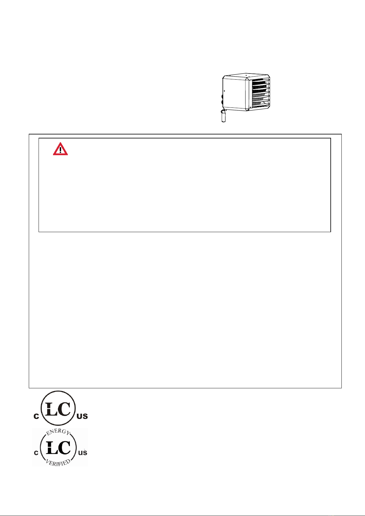
Condensing PREMIX UNIT AIR HEATER
TYPE HR
WARNING
FIRE OR EXPLOSION HAZARD
Failure to follow safety warnings exactly could result in serious injury, death or property damage.
Be sure to read and understand the installation, operation and service instructions in this manual.
Improper installation, adjustment alteration, service or maintenance can cause serious injury, death or
property damages.
•Do not store or use gasoline or other flammable vapours and liquids in the vicinity of this or any
other appliance.
•WHAT TO DO IF YOU SMELL GAS
oDo not try to light any appliance
oDo not touch any electrical switch; do not use any phone in your building.
oLeave the building immediately.
oImmediately call your gas supplier from a phone remote from the building. Follow the
gas suppliers instructions.
oIf you can not reach your gas supplier, call the fire department.
•Installation and service must be performed by a qualified installer, service agency or the gas
supplier.
•Installations in aircraft hangers should be in accordance with ANSI/NFPA No. 409 (the latest
edition), standard for aircraft Hangars; in public garages in accordance with ANSI/NFPA No. 88A
(latest edition), Standard for Parking Structures; and for repair garages in accordance with
ANSI/NFPA No. 88B (latest edition), Standard for repair garages. In Canada, installations in
aircraft hangars should be in accordance with the requirements of the enforcing authorities, an in
public garages in accordance with CSA B149 codes.
This booklet includes installation, operation, maintenance and service information.
Keep this booklet for future reference.
Before beginning to work on the installation, always consult this booklet.
CSA 2.7-2017
CSA P11-2017
ANSI Z83.8-2016 / 2.6-2016 Instruction manual version CSA-EN185b
Heaters for Canada / North America
Date: 01-2018
Heaters for natural gas and Propane

Instructions condensing Air heaters type HR Page 2/25
1Introduction:
This installation and user manual is produced specifically for the gas, electrical and mechanical installer ,
it also gives instructions how to use and maintain the heater.
2Content:
Page
1INTRODUCTION: 2
2CONTENT: 2
3GENERAL 3
3.1 HAZARD DEFINITIONS 3
3.2 FOR YOUR SAFETY 3
3.3 GUARANTEE 3
4APPLICATION INFORMATION 3
4.1 INSTALLATION CODES 3
4.2 INSTALLATION IN AIRCRAFT HANGERS OR PARKING STRUCTURES 4
4.3 GAS TYPE 4
4.4 CONDENSING HEATER 4
4.5 PRE-CHECK INSTRUCTIONS 4
4.6 PROTECTION FROM WATER AND DUST 4
4.7 HAZARDOUS ENVIRONMENT 4
5TECHNICAL DETAILS: 5
6INSTALLATION 7
6.1 RESTRICTIONS 7
6.2 POSITIONING,DISTANCES 7
6.3 INSTALLATION AT HEIGHTS 8
6.4 GAS CONNECTION 8
6.5 ELECTRICAL CONNECTION 9
6.6 VENTING SYSTEM,AIR INTAKE /COMBUSTION PRODUCTS DISCHARGE 9
6.7 CONDENSATE DISCHARGE 11
7FUNCTIONING OF THE UNIT 12
7.1 GENERAL 12
7.2 HEAT DEMAND 12
7.3 DELTA-T-REGULATION (TEMPERATURE CONTROLLED DE-STRATIFICATION FAN) 12
7.4 SUMMER VENTILATION 13
7.5 HIGH LIMIT PROTECTION 13
7.6 FLUE TRANSPORT SUPERVISION 13
8LIGHTING THE APPLIANCE / FIRST START-UP 14
8.1 SAFETY 14
8.2 PUTTING INTO OPERATION 14
8.3 FIRST START UP 15
8.4 GENERAL 15
8.5 START BY USING THE SERVICE-BUTTON 15
8.6 START BY USING THE THERMOSTAT 15
8.7 TO SIMULATE A LOCK OUT CONDITION 15
9ADJUSTING THE GAS-CONTROL 16
10 PROBLEM SOLVING 16
10.1 GENERAL 16
11 MAINTENANCE / SPARE PARTS 18
11.1 GENERAL INSPECTION 19
11.2 INSPECTION OF THE HEATER 19
11.3 IGNITION ELECTRODE 19

Instructions condensing Air heaters type HR Page 3/25
12 EXAMPLES ELECTRICAL INSTALLATION 20
12.1 THERMOSTAT CABLE 20
12.2 INSTALLATION WITH MODULATING ROOM THERMOSTAT 20
12.3 INSTALLATION OF MORE HEATERS ON ONE THERMOSTAT 20
13 ELECTRICAL DIAGRAM 22
14 SPARE PARTS AND EXPLODED VIEWS 23
14.1 SPARE PARTS 23
14.2 EXPLODED VIEW HR-10 24
14.3 EXPLODED VIEW HR-30 25
3General
3.1 Hazard definitions
The following defined terms are used throughout this manual to bring attention to the presence of hazards
of various risk levels or to important information concerning the life of the product
WARNING, danger Indicates presence of hazards that can cause severe personal injury, death or
substantial property damage
CAUTION: Indicates presence of hazards that will or can cause minor or Caution moderate personal
injury or property damage.
INFORMATION: Indicates special important instructions on installation, operation or Notice maintenance
that are important but not related to personal injury or property damage.
3.2 For your safety
WARNING: If you do not follow these instructions exactly, a fire or explosion may result causing property
damage, personal injury or loss of life.
This appliance does not have a pilot. It is equipped with an ignition device which automatically lights the
burner. Do not try to light the burner by hand
BEFORE OPERATING smell all around the appliance area for gas. Be sure to smell next to the floor
because some gas is heavier than air and will settle on the floor.
WHAT TO DO IF YOU SMELL GAS
•Do not try to light any appliance
•Do not touch any electrical switch; do not use any phone in your building.
•Leave the building immediately.
•Immediately call your gas supplier from a phone remote from the building. Follow the gas suppliers
instructions.
•If you can not reach your gas supplier, call the fire department.
Do not use this appliance if any part has been under water. Immediately call a qualified service technician
to inspect the appliance and to replace any part of the control system and any gas control which has been
under water
Installation and service must be performed by a qualified installer, service agency or the gas supplier.
3.3 Guarantee
The guarantee becomes invalidated when the air heaters are not installed in accordance with this booklet.
4Application information
4.1 Installation Codes
This utility heater must be installed in accordance with the manufacturer's instruction and local codes. In
the absence of local codes, follow the National Fuel Gas Code, ANSI Z223/NFPA 54, or the Natural Gas
and Propane Installation Code, CSA B149.1.

Instructions condensing Air heaters type HR Page 4/25
4.2 Installation in aircraft hangers or parking structures
Installations in aircraft hangers should be in accordance with ANSI/NFPA No. 409 (the latest edition),
standard for aircraft Hangars; in public garages in accordance with ANSI/NFPA No. 88A (latest edition),
Standard for Parking Structures; and for repair garages in accordance with ANSI/NFPA No. 88B (latest
edition), Standard for repair garages. In Canada, installations in aircraft hangars should be in accordance
with the requirements of the enforcing authorities, an in public garages in accordance with CSA B149
codes.
4.3 Gas type
The unit is suited for OR natural gas OR LP Propane gas. On the labels on the packaging and the heater
can the gas type be found. itself. In case the heater needs to be converted to another gas type contact
your supplier. It can only be converted by the manufacturer or its representative.
4.4 Condensing heater
This is a condensing heater. This means a condensate water discharge system should be installed
according to local regulations. Never block this discharge. The unit will stop working
4.5 Pre-check instructions
Before unpacking and installation, please check (i.e. on the data badge) if the heater is in accordance
with the order and if it is suitable for the local present provisions (gas type, gas pressure, electrical supply
etc.)
The competent installer must make sure the heater operates correctly and must instruct the user about
the safe operation of the heater.
The heater has been tested in detail on safety and correct operating settings before leaving the factory. It
has been adjusted for the type of gas that is stated on the data badge. Should there be any doubt, please
contact the manufacturer.
Not following these instructions will make the guarantee invalidated
4.6 Protection from water and dust
The heater is not waterproof. This means that it may not be exposed to rain, spry or dripping water.
The is not designed for use in a very dusty environment. Dust may accumulate in the heater and may
cause a defect of the heater. This is also the case for the room-thermostat.
4.7 Hazardous environment
It should be prevented that chlorine or other corrosive containing vapours are sucked into the air intake.
These vapours will result in corrosion of the heat exchanger and a leakage of condensate and flue gas.
Instructions condensing Air heaters type HR Page 5/25
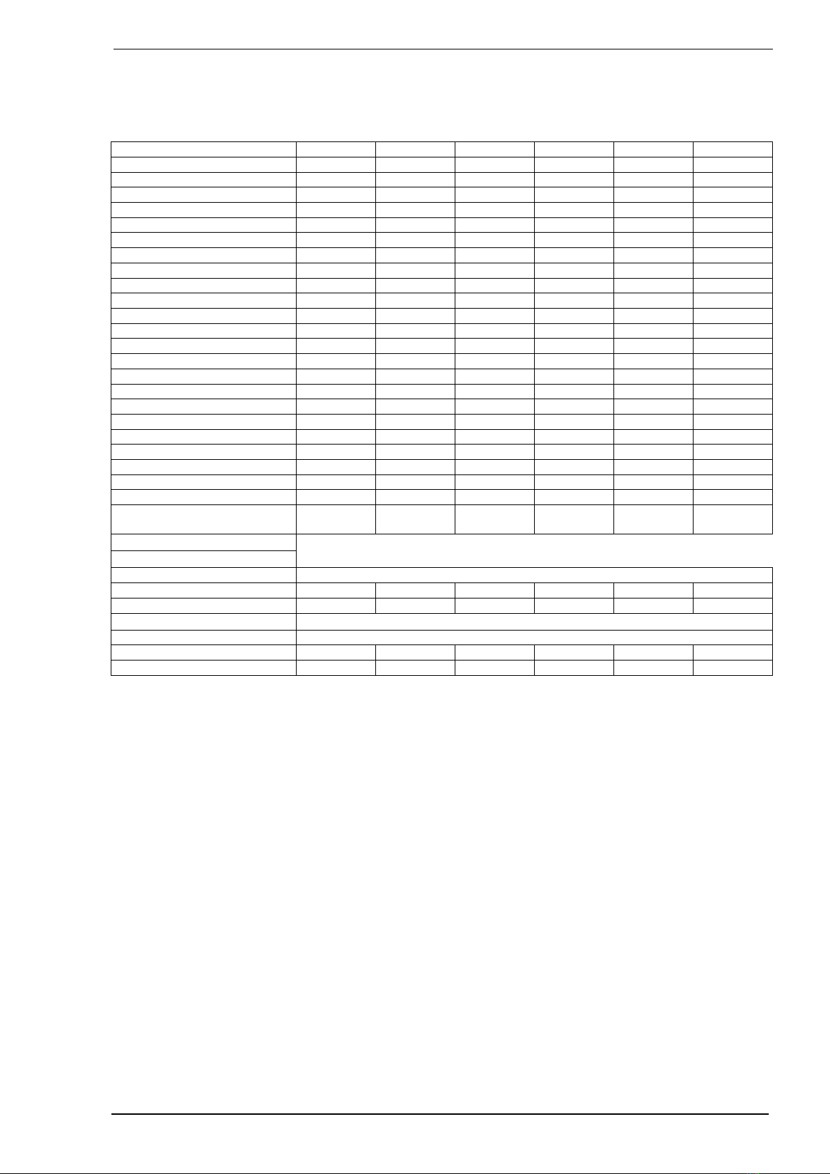
5Technical details:
Commercial name
HR47
HR30
HR76
HR50
HR115
HR75
Btu (nom)
47.000
30.000
76.000
49.000
114.000
74.000
Btu (min)
15.000
15.000
23.000
23.000
34.000
34.000
input kW nom.
13,8
8,8
22,3
14,4
33,4
21,7
input kW min.
4,4
4,4
6,7
6,7
10,0
10,0
Eff @ max NG(%)
86,2
91,2
86,9
92,8
87,4
91,5
Eff @ min.NG (%)
95,3
95,3
97,2
97,2
96,0
96,0
Btu output max
40.500
27.300
66.000
45.400
99.500
67.600
Btu output min
14.300
14.300
22.300
22.300
32.600
32.600
Output kW nom.
11,9
8,0
19,3
13,3
29,2
19,8
Output kW min.
4,2
4,2
6,5
6,5
9,6
9,6
Amps @ 115Vac (A)
2,8
2,8
2,8
2,8
2,9
2,9
P @ 115Vac (kW)
0,325
0,325
0,325
0,325
0,338
0,338
Amps @ 230Vac (A)
1,15
1,15
1,15
1,15
1,21
1,21
P @ 230Vac (kW)
0,265
0,265
0,265
0,265
0,278
0,278
Air output (cfm)
1200
1200
1500
1500
1800
1800
m3/hr
2.000
2.000
2.600
2.600
3.000
3.000
Throw (ft)
49
49
66
66
75
75
m3/hr
15
15
20
20
23
23
Gas connection G”
½” in
½” in
½” in
½” in
½” in
½” in
Flue length max (ft)
30
30
30
30
30
30
(m)
9
9
9
9
9
9
Weight (lbs)
100
100
110
110
165
165
(kg)
45
45
50
50
75
75
Sound level (average @ 13
ft (4m)) (dBA)
45
45
45
45
45
45
NG Natural gas settings
Supply pressure (min-max)
minimal 5,5 IN W.C (1,4 kPa) maximal 20 IN W.C. (5,0 kPa)
CO2 @ high (%)
9,5
9,5
9,5
9,5
9,2
9,2
CO2 @ low
9,0
9,0
9,0
9,0
8,8
8,8
LP Propane settings
Supply pressure (min-max)
minimal 8 IN W.C (2,0 kPa) maximal 20 IN W.C. (5,0 kPa)
CO2 @ high (%)
10,7
10,7
10,7
10,7
11,0
11,0
CO2 @ low
10,3
10,3
10,3
10,3
10,5
10,5
Instructions condensing Air heaters type HR Page 6/25
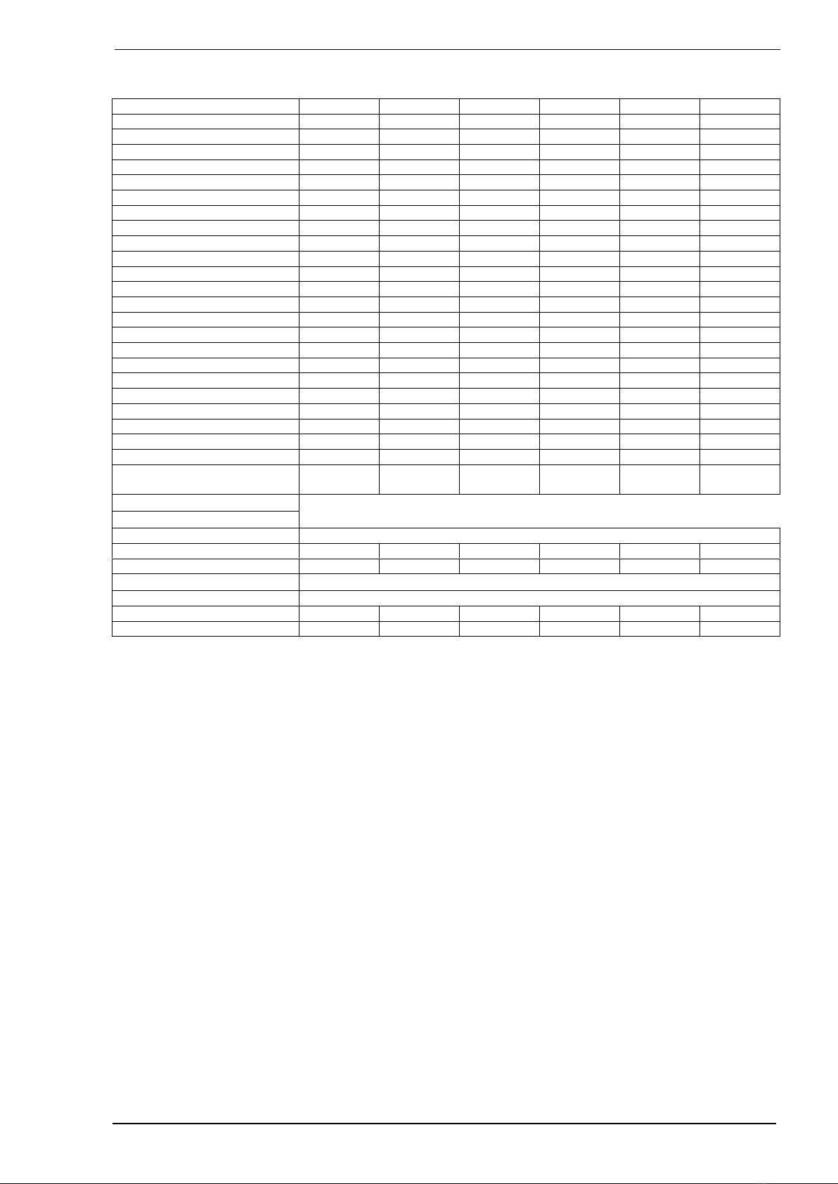
Technical details (cont.)
Commercial name
HR151
HR100
HR190
HR125
HR230
HR150
Btu (nom)
151.000
98.000
189.000
123.000
227.000
148.000
Btu (min)
45.000
45.000
57.000
57.000
68.000
68.000
input kW nom.
44,3
28,7
55,4
36,0
66,5
43,4
input kW min.
13,2
13,2
16,7
16,7
19,6
19,6
Eff @ max (%)
87,1
91,0
87,7
91,6
87,0
91,0
Eff @ min. (%)
95,8
95,8
96,7
96,7
95,5
95,5
Btu output max
131.000
89.200
165.000
112.000
197.000
134.600
Btu output min
43.000
43.000
55.100
55.100
64.900
64.900
Output kW nom.
38,4
26,1
48,4
32,8
57,7
39,4
Output kW min.
12,6
12,6
16,1
16,1
19,0
19,0
Amps @ 115Vac (A)
4,9
4,9
7,0
7,0
7,1
7,1
P @ 115Vac (kW)
0,558
0,558
0,800
0,800
0,820
0,820
Amps @ 230Vac (A)
2,25
2,25
3,3
3,3
3,38
3,38
P @ 230Vac (kW)
0,498
0,498
0,740
0,740
0,760
0,760
Air output (cfm)
2600
2600
2900
2900
3500
3500
m3/hr
4.500
4.500
5.000
5.000
6.000
6.000
Throw (ft)
85
85
92
92
98
98
m3/hr
26
26
28
28
30
30
Gas connection G”
½” in
½” in
½” in
½” in
½” in
½” in
Flue length max (ft)
30
30
30
30
30
30
(m)
9
9
9
9
9
9
Weight (lbs)
187
187
231
231
243
243
(kg)
85
85
105
105
110
110
Sound level (average @ 13
ft (4m)) (dBA)
47
47
48
48
49
49
Natural gas settings
Supply pressure (min-max)
minimal 5,5 IN W.C (1,37 kPa) maximal 20 IN W.C. (5,0 kPa)
CO2 @ high (%)
9,2
9,2
9,2
9,2
9,2
9,2
CO2 @ low
8,8
8,8
8,8
8,8
8,8
8,8
LP Propane settings
Supply pressure (min-max)
minimal 8 IN W.C (2,0 kPa) maximal 20 IN W.C. (5,0 kPa)
CO2 @ high (%)
11,0
11,0
11,0
11,0
11,0
11,0
CO2 @ low
10,5
10,5
10,5
10,5
10,5
10,5
Instructions condensing Air heaters type HR Page 7/25
490125
285
245
M10
420
495
420
680
M10
M10
10011085
65
65
85
35
O40
IN O80
OUT O80
Gas 1/2"
Type 10 & 20 575
795
670
565
575
650125
470
545
M10
4x M10
M10
115
140110
100
105
Gas 3/4" ext.
INO80
OUTO80
325
400
180
=
=
35
85
180815
470
650125
4X M10
565
670
1065
Gas 3/4" ext.
100
115
105
110
140
35
85
IN O80
OUT O80
O40
O40
Type 30 & 40
Type 50 & 60
280
280
280
840
6Installation
6.1 Restrictions
See for application-restrictions in Chapter 4 in this manual.
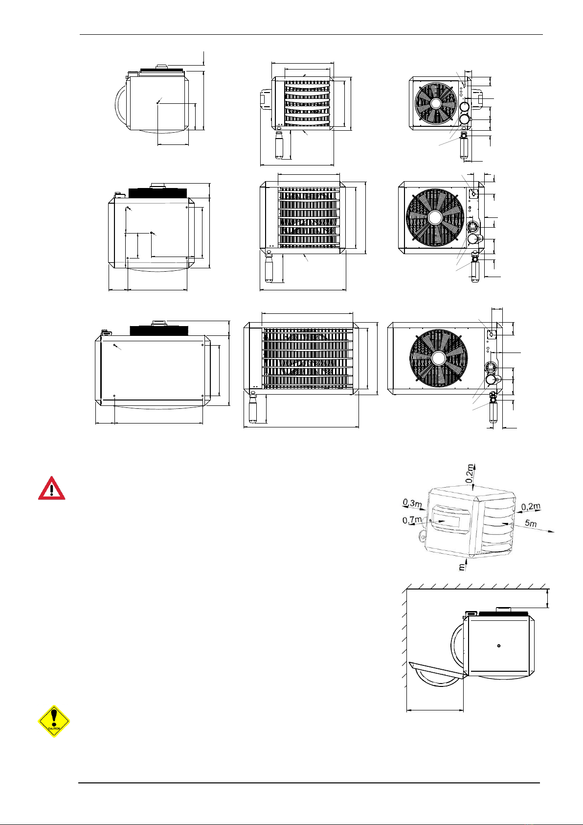
6.2 Positioning, distances
Ventilation gaps around the heater should be maintained from any
flammable materials.
If the heater is installed in a garage, there must me a minimum
clearance above the floor of 18 in (457 mm).
Make sure that there is enough space for the door of the heater to
open.
If this heater is drawing its combustion air from within the room in
where it is located, the necessary combustion ventilation
requirements must be followed for gas safety regulations.
Make sure that the warm air can be blown out freely. There should
absolutely be (no possibility of) materials within 5m from the front of
the heater.
The heater should not be installed in areas containing any corrosive
or explosive vapours, in high moisture or dust concentrations, at
negative pressures or temperatures higher than 30°C; please consult your supplier..
•Check that the support is solid enough.
m
in250
10t/m30min.500mm
40t/m60min660mm
Instructions condensing Air heaters type HR Page 8/25
B
150
390
A
C
XR10-30 XR40-60
HR10-20 HR30-40
A 550 665
B 640 815
C800 990
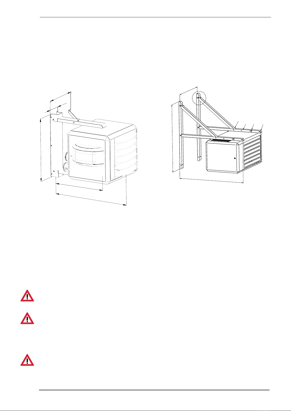
•The heater is designed as free hanging. The heater should be able to blow the warm air free from any
ducting or obstacles. Also the air intake should be free.
•Use preferably the suspension kits from your supplier.
•Make sure that after fitting, there is no mechanical tension on any connecting gas or electric
supplies.
Suspension adapter for type 10 and 20
6.3 Installation at heights
For Installation above 2000 ft (610
m), derate 4% for each 1000 ft (305 m) above sea level.
This can be done by re-adjusting the CO2 in the flue to the values mentioned on the data label and in the
technical table
6.4 Gas connection
The unit is suited for OR natural gas OR Propane gas. It is mentioned on the labels on the packaging and
the heater itself. In case the heater needs to be converted to another gas type contact your supplier. It
can only be converted by the manufacturer or its representative.
The installation shall confirm with local building codes or, in the absence of local codes, with the National
Fuel Gas Code, ANSI Z223.1NPA 54, or the Natural Gas and Propane Installation Code, CSA B149.4
Pipe size running to the appliance depends on: Length of pipe; Number of fittings; Maximum input
requirement of all gas appliances in the property.
A manual isolation valve in the supply line must be placed upstream within reach of the heater.
Strain on the gas valve and fittings may result in vibration, premature component failure and leakage and
may result in a fire, explosion, property damage, serious injury or death.
The appliance and its individual shutoff valve must be disconnected from the gas supply piping system
during any pressure testing of that system at test pressures in excess of ½ psi (3.5 kPa). The appliance
must be isolated from the gas supply piping system by closing its individual manual shut-off valve during
any pressure testing of the gas supply piping system at test pressures equal to or less than ½ psi (3.5
kPa)
The working and standing supply pressure must be for:
Natural gas (NG) minimal 5,5 IN W.C (1,37 kPa) and maximal 20 IN W.C. (5,0 kPa),
Propane (LP) minimal 8 IN W.C (2,0 kPa) maximal 20 IN W.C. (5,0 kPa)
measured at the inlet pressure nipple of the gas control in the heater.
Do not use an open flame to test for gas leaks. Failure to follow these instructions may result in fire
1200
1200
See installation manual
45°
15°&30°
Horizontal
15°30°45°
Horizontal

Instructions condensing Air heaters type HR Page 9/25
6.5 Electrical connection
6.5.1 Power supply
When installed, the appliance must be electrically grounded in accordance with local codes, or in the
absence of local codes, with the National Electrical Code, ANSI/NFPA 70, and/or the Canadian Electrical
Code, CSA C22.1, if an external electrical source is utilized
The unit heater is delivered completely wired internally, where controls of any type are to be added (e.g.
room thermostat) , the relevant wiring diagrams must be followed to. Never use a room thermostat to
interrupt the electrical supply to the heater!
Make provisions to completely isolate the heater for maintenance purposes. This can be an isolation
switch (min.3mm contact opening gap) , a power plug or a non-switched fuse spur. The wiring diagram
for the heater can be found towards the end this manual.
The supply is 1 Fase 60Hz. with earth. The control circuit is a two wire low voltage Argus-link bus
communication.
6.5.2 Room thermostat
The heater can only be controlled by special modulating Winterwarm room thermostats:
The Multi Therm Comfort; modulating digital clock thermostat with optimiser. It can control 1 to 8 air
heaters.
The Multi Therm Standard; modulating digital thermostat. It can control 1 to 8 air heaters.
The Interface printboard; special designed interface module for connecting the air heaters with Building
Mangagement Systems. (0-10V (modulating input) signal, high/low signal, external reset and
other different in and outputs.
In all cases the communication between heater and thermostat is based on a two wire, low-voltage
connection. In the appliance the wire for the thermostat has to be connected to connection 4 and 5 (see
also electrical wiring diagram) Attention: This also needs a change in the settings on the print board, see
chapter 11
When mounting the thermostat, take attention to the following items:
•Mount the thermostat in a place where the air can circulate free pass the thermostat. Take notice
that the sun does not shine directly upon the thermostat (in the winter). Do not place the
thermostat on a cold wall. Place the thermostat on an inner wall free from draught.
Never place the thermostat within the throw of the heater.
6.5.3 Thermostat cable
In all cases the communication between the heater and the thermostat is based on a two wire, low-
voltage connection. In the appliance the wire for the thermostat has to be connected to connection 4 and
5 (see also electrical wiring diagram).
Cable specification: signal cable, 1x2x0,8 mm (shielded and twisted)
Maximum length 250m.
If the cable is chosen too thin, the signal will become too poor. If the cable is not shielded and twisted the
signal might become disturbed in an EMC unfriendly environment.
Keep the thermostat cable separated from mains cables. Connect the earth shield of the cable only to the
earth terminal in the heater.
If these guidelines are not followed it may result in malfunction of the installation or worse, it could
damage the thermostat or the electronics in the heater.
Never mount the thermostat near aerials of internal communication networks. These emit radiation that
could lead to disturbance of the thermostat. Always keep some meters distance.
6.5.4 Fuses
On the heater control there is one 3AT fuse. See electrical wiring diagram.
Replace the fuse only by a fuse of the same type, 3AT
6.6 Venting system, Air intake / combustion products discharge
Make sure that the vent installations shall conform with local codes or, in the absence of local codes, with
the National Fuel Gas Code, ANSI Z223.1/NFPA 54, or the Natural Gas and Propane Installation Code,
CSA B149.1.

Instructions condensing Air heaters type HR Page 10/25
The combined Winterwarm combustion-air supply / combustion-gas outlet device (Roof terminal or wall
terminal) has to be used, only so the installation is approved. See installation drawings.
Always connect a roof terminal for condensing appliances, otherwise condensate can form ice in the
winter on the terminal.
Use only pipes and bends for overpressure with profiled sealing-rings
Make sure the roof terminal is at least 0,5m above roof level to prevent snow from blocking the vent
terminal.
WARNING: All venting terminals must be positioned away from fresh air intakes, doors and windows to
preclude combustion products from entering occupied space. Failure to comply could result in severe
personal injury or death and/or property damage
WARNING: Do not locate venting terminals above passage way’s. In freezing conditions ice may be
formed on the terminal. Failure to comply could result in severe personal injury or death and/or property
damage.
Clearance to vent terminal
Distances from adjacent public walkways, adjacent buildings, openable windows and building openings,
shall conform with the local codes or, in the absence of local codes, with the National Fuel Gas Code,
ANSI Z223.1/NFPA 54, or the Natural Gas and Propane Installation Code, CSA B149.1;
The Natural Gas and Propane Installation Code, B149.1, specifies a 6 ft horizontal vent terminal
clearance to gas and electric meters and relief devices.
Final check
After installing of the venting system check for unused openings and seal the whole venting system..
6.6.1 Flue terminals
Only the flue terminals that are provided with the heater may be used. These terminals are certified
together with the heater.
The following terminals are allowed:
Concentric roof terminal type M&G Skyline 80-80 article: IA8214
Concentric wall terminal type M&G HR80-80 article: IA8216
6.6.2 Flue material
Only single wall, suited for overpressure and temperature class minimum
250°F flue material is allowed.
•Single thick wall (min 1,5mm) aluminium
•Stainless steel according (min 0,4mm)
•Plastic flue material temperature class 250°F
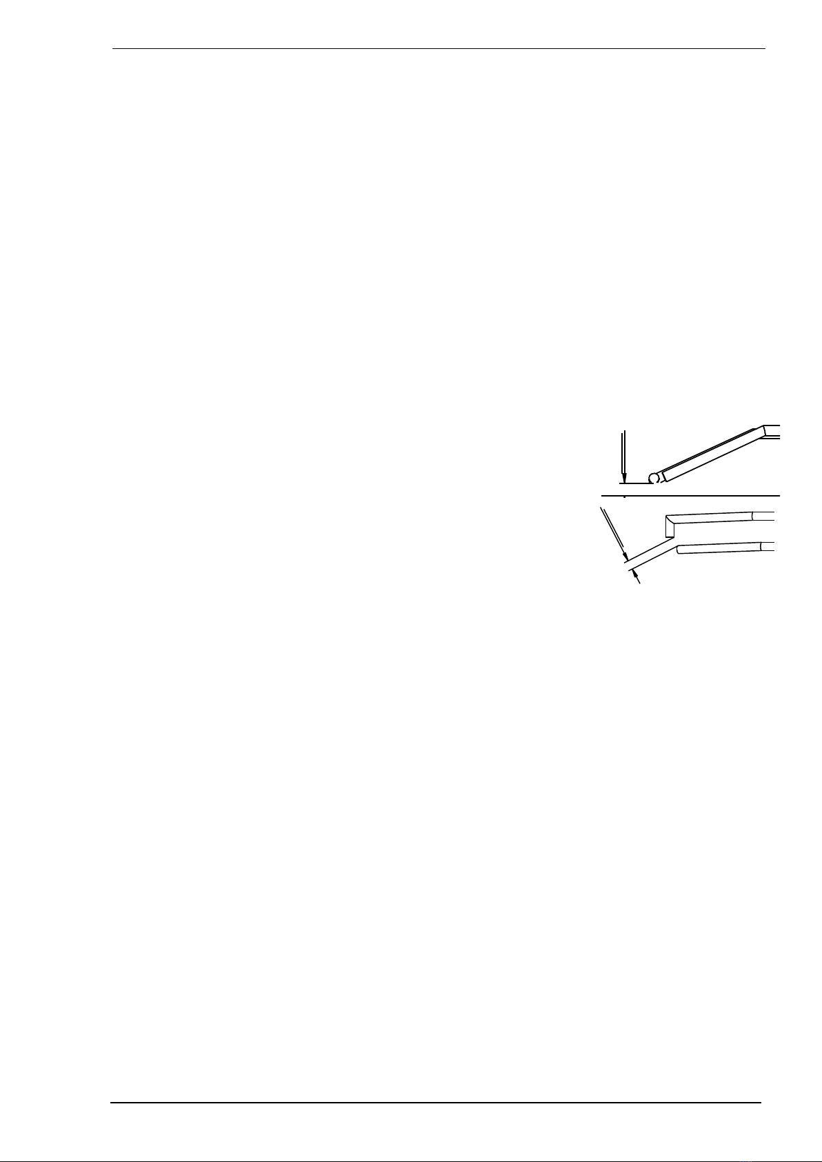
6.6.3 Inclination of the venting system
During heating, condensate is formed in the discharge system. This condensate must flow back into the
heater. Therefore the flue discharge pipes have to be mounted in such a way that the inclination of the
pipes will result in the condensate flowing into the heater (minimum inclination 2 inch per 3 ft (50mm per
meter).
When the condensate flows back from a stainless steel or plastic flue system into the heater, a separate
condensate drain should be mounted before the aluminium flue exit from the heater.
6.6.4 Combustion air intake
Single wall, ridged, aluminium, stainless steel, plastic air tight and should withstand corrosion.
To avoid accumulation of water into the supply pipes, they should also be mounted with an inclination
towards the heater.
6.6.5 Maximum flue length
The maximum pressure drop in either the air supply pipe, or the flue pipe ,must not exceed 10 metres
straight pipe , excluding the terminal. Whenever bends are used the pressure drop is greater and
therefore a 90° bend will count as 2 metres and a 45° bend as 1 metre. All flue pipes must be of the same
diameter as the flue spigots on the heater, and all flue joints must be sealed. For further information
regarding the flue system please contact your reseller.

Instructions condensing Air heaters type HR Page 11/25
575
1370
O125
80O
HOH 110
max 300
135 610
O125
80
HOH 110
In case of a vertical flue terminal, the flue exit should be at least 50cm above the roof. Take also distance
into account with air intake openings to the building. (national or local regulations)
6.6.6 Support of venting systems
The venting system shall be installed in accordance with the installation instructions in this manual.
The portions of the venting system shall be supported to prevent sagging.
•First support element max 1.5 feet (0.5m)from the heater
•Horizontal elements
oSupport every separate element minimal once
oMax distance between supports 3 ft (1m)
•Vertical elements
oMax distance between supports 6 ft (2m)
•Every venting system needs at least 1 support
6.7 Condensate discharge
The condensate discharge pipe is on the bottom of the heater. The separate delivered siphon has to be
connected to the condensate Ø40mm PVC pipe. On the siphon a pipe Ø 40mm can be mounted. The
discharge system after the sifon has to be minimum Ø25mm and mounted with an inclination to the
sewer. The advised inclination should be minimum 30mm per meter. The horizontal length should not
exceed 5 meter.
The condensate should connected according to local and national regulations. Do not let the condensate
drip on the roof or roof edge outside the building, dangerous ice can be formed in the winter. Condensate
should be drained away to the sewer.
The condensate outlet from the heater should never be closed.
Protect the condensate drain from freezing. Ice can also close the condensate drain.
To be sure that the condensate can always flow out of the heater, an extra siphon should be mounted
before connecting to the sewer.
When the condensate discharge system is placed the siphon has to be filled with water. This is important
because otherwise the flue gases can flow into the room where the heater is placed.
The heater can be mounted also with the hot air blowing to the ground. In this case the condensate pipe
has to be mounted to the front connection of the heater. Therefore the small sheet metal in the front of the
heater can be removed and the pipe can be replaced to the front of the heater.

Instructions condensing Air heaters type HR Page 12/25
! 180°
“
!g> -2°
45°
A
DETAIL A
! 180°
“
Maximum condensate rate:
Type HR
HR10
HR20
HR30/35
HR40
HR50
HR60
Max. Condensate l/hr
2
2
3
3
4
4
7Functioning of the unit
7.1 General
The unit can heat as well as ventilate. By using the temperature-sensor on the unit and the one in the
room-thermostat, the temperature-difference between the two in the room is monitored. Should the
difference become higher than a set value, due to the fact that warm air has accumulated underneath the
roof, the system-fan will start and push the warm air down, acting as a de-stratification fan.
7.2 Heat demand
If the thermostat indicates heat demand, the following cycle will commence:
1.Pre purge: The electronic circuit board acknowledges the heat-demand and the premix burner fan
will start running. The Pressure switch should be made, and then the fan purges for 30 seconds.
2.Ignition: After the 30 seconds of pre purge the electrode will spark for max. 5 seconds, the gas
valve is opens and the gas-air mixture will ignite.
3.Burn: When the flame is detected the unit will modulate to the desired load after ca. 15 seconds of
stabilisation time. The system fan will start modulating (step-less) as well. The air heater will
always burn for a minimum of 4 minutes.
4.End of heat demand: When the heat demand ends, the burner will switch off and the system fan
will continue to run for ca. 3 minutes in order to cool the unit down.
The unit will try to ignite twice before lockout on flame fault.
In the case of flame failure during operation, the heater will attempt one restart.
When the heater is in lockout you see the led on pcb will turn red. In the display from the thermostat you
will see an A1.
7.3 Delta-T-regulation (temperature controlled de-stratification fan)
In case there is no heat demand, the delta-T-regulation will be active.
When the temperature-difference between the sensor on the unit (the NTC) and the sensor in the
thermostat is bigger than the set value (factory setting standard 8°C), the system fan will start, at a
regulated speed, depending on the differential temperature difference. This operation ensures an even
temperature distribution throughout the building, thus acting as a fully automatic variable de-stratification
fan. Should this delta-T-regulation not be required, in the Menu Program Settings on the room thermostat
this regulation can be switched off. See user manual of the special Winterwarm Room thermostat.

Instructions condensing Air heaters type HR Page 13/25
7.4 Summer ventilation
It is possible to let the ventilator run on a certain speed in the summer. Please follow the instructions in
the manual from the thermostat.
7.5 High limit protection
7.5.1 T max. Heat exchanger
The unit contains 2 temperature protections. The NTC thermostat monitors the air temperature
electronically. Should the temperature, in a first step, become too high, the burner will modulate to the
minimum input and the system fan will modulate to the maximum speed.
When the temperature still increases, the burner will switch off (on display you see intermittent an E1).
When the heat exchanger has been cooled to normal levels the burner will start automatically.
Should the temperature increase to an unacceptable level, the heater stops (on the display you see
intermittent A2). Only after a manual reset the heater can start again. Manual reset can be done on the
electronic circuit board or with the special Winterwarm Room thermostat
7.5.2 T max. Flue gas outlet
For the application of plastic flue material on the HR heaters the maximum flue gas temperature is
monitored (Tflue < 120 °C). A temperature sensor in the flue outlet the heater monitors the temperature of
the flue. When the flue temperature is too high (Tflue > 110 °C), the burner modulates its capacity to the
minimum. When the temperature keeps rising, and reaches 115°C, the burner stops. When after an
automatic restart the situation repeats itself the heater will lock out. The error A7 will show in the display.
7.6 Flue Transport Supervision
The unit is provided with a pressure switch to control the transport of combustion air through the heat
exchanger. It checks in the pre purge phase if there is sufficient movement of combustion air through the
heat exchanger by measuring the pressure difference over the heat exchanger. If the pressure difference
is too low in the pre purge phase, default A9 will occur. This could mean that combustion air is leaking
from the heat exchanger and so the heat exchanger must be checked on leakage.
Instructions condensing Air heaters type HR Page 14/25
8Lighting the appliance / First start-up
Use of electrical connections to the heater other than described might result in unpredictable behaviour,
or malfunction. DO NOT WIRE ANY VOLTAGE, ONLY DRY CONTACTS TO CONTROL BOARD
Before Start-up refer to Mandatory Pre-commissioning Procedure for (Plastic) Venting Failure to follow
these instructions can result in explosions, injury or death.
Prior to turning the gas supply on and lighting the appliance, ensure all aspects of the installation are
complete and in conformance with the instructions provided in this manual, including the Vent/Air-Intake
sections and the manuals delivered with the vent system and Condensate Drain. Failure to precisely
follow these instructions will cause a fire or explosion resulting in property damage, serious injury or
death.
Do not store or use gasoline or other flammable vapours & liquids in the vicinity of this or any other
appliance. Failure to follow instructions could result in explosion causing property damage, serious injury
or death.
If you do not follow these instructions exactly, a fire or explosion may result causing property damage,
serious injury or death.
Should overheating occur or the gas supply fail to shut off, turn off the manual gas control valve to the
appliance. Failure to follow instructions could result in explosion causing property damage, serious injury
or death.
8.1 Safety
WARNING: If you do not follow these instructions exactly, a fire or explosion may result causing property
damage, personal injury or loss of life.
This appliance does not have a pilot. It is equipped with an ignition device which automatically lights the
burner. Do not try to light the burner by hand
BEFORE OPERATING smell all around the appliance area for gas. Be sure to smell next to the floor
because some gas is heavier than air and will settle on the floor.
WHAT TO DO IF YOU SMELL GAS
•Do not try to light any appliance
•Do not touch any electrical switch; do not use any phone in your building.
•Leave the building immediately.
•Immediately call your gas supplier from a phone remote from the building. Follow the gas suppliers
instructions.
•If you can not reach your gas supplier, call the fire department.
Do not use this appliance if any part has been under water. Immediately call a qualified service technician
to inspect the appliance and to replace any part of the control system and any gas control which has been
under water
8.2 Putting into operation
1.STOP! Read the safety information above very carefully.
2.Turn off all electric power to the appliance.
3.Set the thermostat to lowest setting.
4.Do not try to light the burner by hand.
5.Make sure the gas line is de-aired. Wait five (5) minutes to clear out any gas. Then smell for gas,
including near the floor. If you smell gas, STOP! Follow the safety information above. If you don't
smell gas, go to the next step.
6.The main gas switch should be situated upstream in the gas line near the heater. Close the main
gas switch.
7.Wait five (5) minutes to clear out any gas. Then smell for gas including near the floor. If you smell
gas, STOP! Follow the safety information above on this page. If you don’t smell gas, go to the
next step.
8.Open the gas supply
9.Turn on all electric power to the appliance.

Instructions condensing Air heaters type HR Page 15/25
10. Set the thermostat to desired setting. And wait for the heater to start.
11. If the appliance will not operate turn off gas to appliance and call your service technician or
gas supplier.
8.3 First start up
The initial lighting of the appliance must be performed by a licensed Gas Technician. Failure to follow
these instructions may result in property damage, serious injury or death. As soon as the appliance has
been fully installed (with regard to de-air of installation, gas, flue gas, air intake, wiring etc.) according to
the preliminary installation instructions, it's allowed to put the power plug into a grounded wall socket. The
grounded line cord and grounded wall socket must be reachable for service purposes at any time.
Ensure the gas shut-off valve is turned on (only after ALL air is purged out), and that the gas system has
been fully tested for leaks.
8.4 General
Prior to packaging, each unit is checked in detail on safety and well functioning. It is a.o. adjusted to the
right efficiency of combustion. In general, the heater does not need to be adjusted after installation, only a
check of well functioning is necessary by a competent person. Also obtain a flue gas analysis and record
it for later reference.
Use only a calibrated instrument !
The CO2 value may be adjusted if necessary, only do this in case it turns out that the CO2 value is not
correct. Do not ever turn injudiciously the adjusting screws!
Adjustment of the gas control without a supporting flue gas analysis will invalidate the warranty.
Once the unit is installed according this manual, the unit can be put into operation. Make sure the gas
pipe is clean, gastight and free from air.
Switch on the electric supply with the maintenance-switch, and open the door in order to be able to
observe the first start-up and so become familiar with the functioning of the heater.
Should the gas line not be purged correctly the heater will attempt to start twice before going into a lock-
out condition. Manual reset is necessary in that case.
Do not forget to instruct the end user about a safe use of the heater (presence of gas, place of the
manual gas valve !), the operation of the heater (lock-out indication and reset) and about the necessary
maintenance. This manual must be left with the end user.
8.5 Start by using the service-button
Press the service-button once for 10 seconds, and the unit will commence the ignition-cycle; (30 sec pre-
purge, ignition, 15 sec flame stabilise, modulating operation) The burner will then start on minimum load
Display print ➔L/b . By pressing the service-button again, the burner will go to maximum load. Display
print ➔H/b
Pressing the service-button for a third time will put the unit into normal operation. (depending if there is
heat demand from the room thermostat).
8.6 Start by using the thermostat
Put the thermostat in the highest position. The start sequence is always the same as 8.2.
8.7 To simulate a lock out condition
Close the manual gas supply valve. The heater will go to lock-out after a restart attempt. The display on
the electronic circuit board shows [A 1]. The red LED will light as well. Check also the function of the
reset button (with gas valve open again), and observe if the heater starts smoothly.
Display on the print board
0
stand-by
Stand-by
1
Pre-purge
System checks and 30 sec pre purge of the burner fan
2
Ignition
The ignition electrode sparks 5 sec. and the gas valve opens, within
5 sec flame detection should occur.
b
Burn
After 15 sec stabilisation time, the heater will modulate to the
desired power. The heater will remain burning minimum 4 minutes.

Instructions condensing Air heaters type HR Page 16/25
P
Post purge
The heater will cool the heat exchanger for 3 minutes, and the
premix fan will post purge for 1 minute.
F
Summer ventilation
The system fan is running on the summer ventilation mode
F
Blinking
Delta-T-regulation
The system fan is running on low position on Delta-T-regulation
L/1/2/
…Blinking
Service Low
The heater is running on the service mode. When the heater burns,
the heater will run on minimum power.
H/1/2/
…Blinking
Service High
The heater is running on the service mode. When the heater burns,
the heater will run on maximum power.
9Adjusting the gas-control
In principle, it is not necessary to adjust the gas control after putting the unit into operation.
In case it needs to be adjusted, (e.g. after fitting a
new one), this must be done only by a qualified
person. Only use calibrated instruments ! A
poor adjustment can lead to overheating and / or
production of the poisonous carbon monoxide !.
There are two screws to adjust the gas control,
the Offset adjuster and the Ratio adjuster.
The Offset adjuster is used in Low fire. The Ratio
adjuster is used in High fire.
Put the heater into operation at high fire by pressing the service button first 10 seconds and press again
shortly. You see on display H/b.
If the heater does not ignite while sparking, you can, if necessary, close the air-openings of the coloured
ring on the gas-air mixer with thumb and forefinger during ignition. The mixture will become richer and will
ignite more easily.
Look for the correct CO2 values in the table with technical data.
Readjust the CO2 when the deviation is more then 0,3%
1 Check the CO2 in High fire
Decrease CO2 →turn the Ratio adjuster to the right (less gas).
Increase the CO2 →turn the Ratio adjuster to the left (more gas).
2 Then check the CO2 in Low fire. The CO2 in low fire is lower then the high fire CO2.
Decrease the CO2 →turn the Offset adjuster to the left.
Increase the CO2 →turn the Offset adjuster to the right
After adjusting the CO2 in Low fire, return to high fire, and Readjust the CO2 with the Ratio adjuster.
Then return to Low fire again and eventually readjust the CO2 with the Offset adjuster.
Repeat these steps until both values are oké.
Never forget to check the CO (carbon monoxide ) production of the heater!!! Too much CO means mostly
that the mixture is too rich. CO value should always be below 100 ppm.
10 Problem solving
10.1 General
When it turns out that the problem is not caused by the external circumstances (i.e. no electric supply
power or no gas), please take the following instructions into account. Please remember the built in waiting
times of the heater (do not react too soon!) and the signals of the LEDs and the code on the display on
the electronic circuit board.
Offset adj.
Ratio adj.
P out
P offset
P in

Instructions condensing Air heaters type HR Page 17/25
To simplify the investigation of the failing heater please check first:
•Check the fuses as well as the wires and plugs in the heater for possible loose contacts.
•In a heat-demand situation, the green LED on the heater must light up.
•In a failure situation, the red LED on the heater must light up, if so, reset.
•Use first the service-button to put the heater in run mode, try later the room thermostat.
Volatile lock out Can only be reset by hand
A/0
Blinking
Internal failure
Print board defective
A/1
Blinking
No Flame
Within 5 sec flame, then flame failure: Case 1:
No flame: Case 2
A/2
Blinking
Exchanger too hot
Heater stops on temperature heat exchanger too hot. Case 3
A/3
Blinking
Sensor error
Temperature sensor on heat exchanger error. Case 4
A/4
Blinking
Too many flame
failures
Too many flame failures on ionisation; Case 1, 5
A/5
Blinking
Internal error
Print board defective
A/6
Blinking
Safety relays
Safety relay failure Case 10
A/7
Blinking
Flame
Flame detection when there should not be a flame or
The flue gas temperature sensor detects an error condition, case 12.
A/8
Blinking
Burner fan
Burner fan dos not run; Case 6
Burner fan runs; Case 7
A/9
Blinking
Pressure switch
Insufficient air transport over the heat exchanger, Case 11
Non volatile lockout Will disappear when the error is cleared.
E/0
Blinking
Internal defect
Print board defective
E/1
Blinking
1etemperature
safety
Heater stops on temperature heat exchanger too hot. When heater is
cooled down the heater will restart. Case 3
E/2
Blinking
Selection resistance
Heater recognition does not work Case 8
E/3
Blinking
Selection resistance
Heater recognition does not work Case 8
E/9
Blinking
Reset error
Too many switches on reset button Case 9
Case 1: Within 5 sec flame, then flame failure.
•The flame is not detected. Check the ignition cable and electrode. (cable resistance 1K ohm
•The heater has electrically a poor earth.
•The print board is defective.
Case 2:
•There is not enough gas pressure.
•The mixture of gas/air is poor, adjust the gas valve
•The gas valve does not open, check during ignition on 230V on the valve.
•Check whether the ignition electrode sparks, replace cable, electrode
Case 3: Heat exchanger too hot

Instructions condensing Air heaters type HR Page 18/25
•Check whether the system fan blows enough air.
•Check the setting of the gas valve, the heater may me overloaded.
Case 4: Temperature sensor on heat exchanger error.
•The sensor has internally 2 sensors. These differ too much. Measure the resistance from each
sensor, the resistance should be 20K at 25° en 25K at 20°. If the measured values differ too
much, replace sensor.
•Rotate the sensor ¼ turn. So the contact point is different on the sensor housing.
Case 5: Too many flame failures while burning
•The setting of the gas valve is not ok, adjust the gas valve
•The flue outlet is blocked
Case 6: The premix does not run
•Premix fan is Blocked or the wiring is bad
•Premix fan is defective
Case 7: The pre-mix fan runs, but not the correct speed.
•Check if the fan runs smoothly.
•Check the wiring.
Case 8: Selection resistance error
•Check the appliance recognition part, replace if necessary
Case 9: Reset button error
•Too many switches on reset button in a short period of time. These error will disappear after
some time, or if the main power is disconnected for a while.
Case 10: Safety relay error
•Plug J4 is not connected well, the bridge on connector 4 between 5 and 11 is not connected well.
•Otherwise change printboard.
Case 11: Insufficient air transport over the heat exchanger
•Check the pressure switch and the connections
•Check the heat exchanger for flue leakage
Case 12: the flue gas temperature sensor detects an error condition
•The flue gas temperature > 120 ° C ➔insufficient air transport of the system fan or burner
adjustment is not correct, check CO2 and CO percentages.
•Loose or closed contact temperature sensor circuit, check the wiring
•The flue gas temperature sensor faulty, check the resistance value of the RG sensor
➔20 k at 25 °C and 25 k at 20 °C.
Heater does start, but shows other problems.
Heater ignites explosively, has often flame failures:
•Check the right setting of the gascontrol, the right CO2 setting is important for the correct ignition.
•Check the ignition cable (1kOhm )
•Check the setting of the ignition electrode, the spark has to be formed between the electrodes
and not between the electrode and the burner.
Insufficient output
•The heat output of the heater will be insufficient if there is too much resistance in the inlet- or
outlet flue system. In this case the premix-burner-fan will be on full speed, but because of the
high resistance too little air is moved and therefore also too little gas. The pressure in the outlet
flue for example, will normally never be above 30 Pascal.
Non modulating system fan
•System fan (M1) does not start or does not vary in speed; Check first the functioning of this fan
by connecting it to 230 Volt. Check with a multi-meter if the different lower tensions are
secondary present on the transformer as well. The fuse could have failed. If the motor and
transformer are OK, the cause of the problem must be in the heater control HC, as the heater
control HC dictates the different voltages from the transformer to the fan-motor. In that case,
replace the heater control HC.
11 Maintenance / spare parts
The heater must be inspected and cleaned regularly (once a year) by a qualified installer who
understands this appliance.
This is all the more important as the circumstances are heavier, especially in case of dust, humidity, high
frequency of switching on/off etc.
Activities:
Instructions condensing Air heaters type HR Page 19/25
11.1 General inspection
•Check the overall condition of the installation. Check the heater, the thermostat, the wires and the
gas line.
•Clean and inspect the condensate pipes and the siphon every year. Always fill the siphon after
cleaning with water to prevent flue gas escaping in the room.
11.2 Inspection of the heater
Before starting the inspection, switch off the electric power to the heater with the maintenance-switch and
close the manual gas valve.
•Take out the burner, complete with flange and pre-mix fan, by unscrewing the 6 off M6 socket screws
and you have taken off the ignition and fan wires
•Check the heat exchanger from the inside for dirt and/or damage.
•Check the burner on damage and clean the ignition electrode if necessary . CAUTION: do not twist
the electrode out of shape!
•Check the air supply and the flue discharge.
•Clean eventual the inside of the heater with a vacuum cleaner.
•In case the heat exchanger is dirty on the outside, clean it with a soft brush. Never use a steel wire
brush!
•Clean the fan-grid with a vacuum cleaner and a brush.
•Put the burner back in (renew the gasket)
After this, check the heater on efficiency of combustion and adjust these if
necessary
Check the heater operates correctly.
11.3 Ignition electrode
For the correct ignition of the burner it is important that the ignition
electrode is adjusted right.
•The distance between the electrode and the burner should be 5.0
±0.5 mm.
•The distance between the two electrodes should be 3.6 ±0.4 mm.
•Check the setting of the ignition electrode, the spark has to be
formed between the electrodes and not between the electrode and the burner.
5±0,5
3.6±0,4

Instructions condensing Air heaters type HR Page 20/25
PE
N
54
L
12
11 76
22°C
NL
12 Examples electrical installation
12.1 Thermostat cable
In all cases the communication between the heater and the thermostat is based on a two wire, low-
voltage connection. In the appliance the wire for the thermostat has to be connected to connection 4 and
5 (see also electrical wiring diagram).
Cable specification: signal cable, 1x2x0,8 (shielded and twisted)
Maximum length 200m.
If the cable is chosen too thin, the signal will become too poor. If the cable is not shielded and
twisted the signal me become disturbed in an EMC unfriendly environment.
Keep the thermostat cable separated from mains cables. Connect the earth shield of the cable only to the
earth terminal in the heater.
If these guidelines are not followed it may result in malfunction of the installation or worse, it could
damage the thermostat or the electronics in the heater.
Never mount the thermostat near aerials of internal communication networks. These emit
radiation that could lead to disturbance of the thermostat. Always keep some meters
distance.
12.2 Installation with modulating room thermostat
•Connect the heater to Mains
•Connect the thermostat to the terminals according to the
diagram. (terminal 4 and 5)
•On the print the switches S2 and
S3 need to be set as follows: S2
switch 1 at the ON position, and S3
at 1.
The change of these switches need to be performed without power on
the Heater, otherwise these settings take no effect.
12.3 Installation of more heaters on one thermostat
One room thermostat can control 8 heaters. To connect the
heaters is very simple. The two wires for the thermostat can be
connected to heater one, from heater one to heater two , from
heater two to heater three etc. etc. Connect always on terminal
4 and 5. See also the diagram.
Standard factory setting: switch 1 “on”.
Each heater needs his own unique number to recognise the
heater by the room thermostat. The number of the heater can
be set by the micro switch on the heater control HC in the
heater. The number at the upper position of the switch is the
given number for that heater. Make sure that each heater has is own unique number. If more than one
heater have the same number the system does not work.
The change of these switches need to be performed without power on the Heater, otherwise these
settings take no effect.
Diagram for more heaters on one thermostat
1 2 3 4 5 6 7 8
ON 1
0
S3
S2
1 2 3 4 5 6 7 8
ON
1 2 3 4 5 6 7 8
ON
1 2 3 4 5 6 7 8
ON
Heater 1
Heater 2
Heater 3
01
S2 S3
01
01
This manual suits for next models
17
Table of contents
Popular Heater manuals by other brands


Pinnacle
Pinnacle Master MH-70-SS-A User's manual & operating instructions

Slant/Fin
Slant/Fin Multi/Pak 90 installation instructions

stockli
stockli Fredy Dubach 8572.50 quick start guide

emk
emk DRACO operating instructions

Empire Heating Systems
Empire Heating Systems RH-25-8 Installation instructions and owner's manual

Truma
Truma S 3004 installation instructions


