Eco Range Oil Condensing Boiler Operating manual
ECO RANGE
Cooker
Oil Condensing Boiler model
For use in Great Britain and Eire (GB & IE)
Instructions for Use, Installation and
Servicing
This appliance must be installed in accordance with the regulations in force and only used in
an adequately ventilated space. Please read these instructions before installation and use and
retain for future reference.

1. Introduction
Thank you for choosing to purchase the condensed oil, balanced flue, Eco Range cooker.
Each cooker is manufactured and assembled by hand in our factory. This appliance is
designed to be capable of operating for long periods of time. With correct installation and
use your Eco Range cooker will provide many years of satisfactory service and cooking
enjoyment.
The appliance consists of two hotplates, a top oven and a bottom oven or warming
compartment. The left sided hotplate is designed for more rapid heating suitable for frying
and boiling, whereas the right sided hotplate is more suitable for slower cooking and
simmering. Hotplate covers are provided to prevent heat losses when not cooking. The two
top ovens operate to provide a consistent temperature controlled environment for all your
cooking and baking needs. The bottom oven operates at lower temperatures and is suitable
for slow cooking or merely as a warming compartment, depending on the control setting.
These instructions detail how to get the most from your cooker, as well as fundamental
information on how the cooker shall be installed, maintained and used in a safe and practical
manner. It is important that some time is taken to read these instructions carefully
before installation and use of the appliance.
In order for the warranty to remain valid it is imperative that the appliance be installed in
compliance with all relevant national and regional regulations.
A competent heating and plumbing engineer must design and approve the proposed system.
The warranty of your Eco Range Cooker applies to products sold in the UK and Eire
only. For products sold outside of these areas please contact the manufacturer for
details warranty authorisation.
2. Safety Instructions
Safety First:
This is a heating appliance; therefore it can become very hot when in service.
Young children and pets should be kept a safe distance from the cooker.
Ceiling mounted clothes dryers are strongly unadvised as they can present a fire hazard, this
also includes leaving towels on the handrail of the cooker.
Pans, especially chip pans, should not be left unattended on the Eco Range cooker.
Read and understand this booklet before installing and operating this appliance.
This appliance must be installed in accordance with the rules in force and used only in a
well ventilated space.
The appliance must only be installed and serviced by a suitably qualified and registered
technician.
The appliance shall not be altered in any way and only approved spare parts shall be
used. Failure to do so will invalidate any warranty or guarantee.

This appliance is very heavy and every care should be taken when trying to manoeuvre
it. Do not attempt to move or lift the appliance by the door handles, this could cause
damage to the doors and handles. It must be sited on a solid, level floor constructed in
accordance with any Building Regulations which may apply to the site.
It is important for the correct operation of this appliance that the installation space and
clearances around the appliance are in line with the specifications detailed in these
instructions.
Sufficient space should be available to allow the doors to be fully opened in excess of
120°from the closed position.
Ventilation openings on the side rear and front of the appliance should never be blocked
or restricted. see ventilation requirements
This appliance is capable of being operational at all times. Parts of the appliance will
become very hot, and remain hot for long periods. Only adults should operate this
appliance and only in accordance with the user instructions. Care should be taken when
using the cooker and the use of oven gloves is recommended when applicable. Children
should be supervised at all times if in the vicinity of the cooker.
In the interest of hygiene and safety the cooker should be kept clean at all times.
The cooker is designed for cooking foods only and must not be used for any other
purpose.
Always allow to cool before cleaning and carrying out maintenance work.
Do not use unstable or unsuitable saucepans and position handles away from the edge of
the hot plate. Thick, flat based saucepans are recommended for best results.
Do not place combustible materials onto the hot plate surfaces even when the cooker is
off.
Your Eco Range Cooker should be serviced at least once every twelve months. It is
impossible to service your cooker while it is hot, therefore DO NOT use your appliance
12 hours before a service is required.
Important:
The installer is responsible to ensure that all persons involved in the installation be provided
with the correct health and safety clothing when handling materials which are known to
cause potential harm.
Ceramic materials: Facemask and gloves must be worn, Contact with eyes, skin and
throat must also be avoided.
Fuels: Wear gloves –avoid ignition sources –Waste fuel should be disposed of
correctly, not via domestic waste water courses.
Fire cement: Wear gloves –wash hands.

Safety Notices and Regulations
The Building Regulations –Part J England and Wales –Part F section III Scotland –
Part L Northern Ireland –Part J Ireland.
BS5440 Parts 1 and 2 Installation of Flues and Ventilation.
D.M.2. Installation of Timber Framed Buildings.
Safety Document 635 The Electricity at Works Regulations.
BS7671 Requirements for Electrical Regulations.
REC Rules regarding PME Earthing (where applicable)
Warning:
Correct earthing must be provided for this appliance.
If in doubt seek advice from a qualified electrical engineer. Prior to carrying out any
work on the appliance switch off at the mains and remove the fuses from the fused spur
outlet and from the user control panel. Replace when works are complete. Always ensure
appliance is ‘electrically dead’ prior to working on the electrics.
3. Technical Specification
Appliance type - Cooker and Space heater
Cooker Burner System - Eco Flame Minor
Fuel - 28-35 sec Kerosene
Country of Designation I.E & U.K
Mains supply - 230 Vac @ 50HZ from a dedicated fused spur.
Fuse rating - 3A
I.P Protection - 20
Load (Running) - 130W (Nominal)
Oil Pump working pressure - 115 psi/ 8 bar (Nominal)
Flue - Balance only.
Appliance total energy input - 42KW (Cooker & boiler)
Installation requirements - Must be installed in accordance with good practise
and as laid down by all relevant codes of practise
by suitably qualified installers.
NB: See Installation Instructions within this manual
Balanced flue only - No further ventilation required.
4. Appliance Details
Overall Size - Height (to hob) 910mm
Width (standard models) 1000mm
Depth (to towel rail) 730mm
Hotplates –340mm diameter x 2

Ovens - Height 270mm
Depth 500mm
Width 345mm
Your cooker is fitted with a thermostatic control device. This operating system provides the
exact heat requirements selected (by the user) for cooking and reduces the overall oil
consumption. The user selects the desired cooking temperature and when the cooker
approaches the selected operating temperature the thermostatic control operates to turn off
the burner flame to maintain a steady temperature. The control knob on the device is marked
which relates to a particular temperature setting of the top oven.
4.1 Using your hotplates
Your appliance has two hotplates, with a joint hotplate in the middle, protected with two
insulated lids which should remain in a closed position when not using the hotplate. The lids
can be raised independently if only using one hot plate. The hot plate temperature is
dependent on the setting of oven temperature. The higher the temperature in the ovens, the
hotter the hotplate will become.
The design of the hot plates is such that the left hand side will become the hottest, making
this suitable for deep fat frying, shallow frying and boiling.
The surfaces of the hotplates are ground flat and it is therefore recommended that all
utensils used have a solid, flat base to come in complete contact with the hot plate for
efficient results.
4.2 Using your Ovens
Your appliance has 2 ovens. The thermostatic dial in the top oven door provides an
indication to the top oven temperatures. This thermometer reading will reduce quite
dramatically when the door is opened and only recover slowly when the door is closed. This
occurrence does not mean that the oven temperature has reduced. The bottom oven is
warmed by the underside of the oven above. Depending on the control device setting and
operational time, this oven will generally operate some 85 –90°C below the top ovens. It
may be used for small food cooking, biscuits, cakes etc but it is best used as a warming
compartment.
4.3 Overheat thermostat
The cooker is protected by an overheat thermostat designed to shut down the burner if a
fault occurs leading to excessive oven temperatures. The overheat thermostat is located
below the control device, inside the lower left compartment. To reset, unscrew the
protective cap and press the button.
NOTE: If overheat reset occurs more than once contact your service technician.

4.4 Cleaning your cooker
CAUTION: Cleaning of the Eco Range Cooker should only be carried out when the
appliance has cooled down.
The Eco Range cooker should be wiped over daily with a damp soapy cloth. The enamel
should then be dried and polished with a soft dry cloth to avoid streaking. Any spillages
should be wiped up immediately to prevent hardening of deposits which would make
removal difficult at a later stage.
The hot plates can be kept clean by using a light suede wire brush and gently scrubbing the
plates, taking care not to damage the surrounding enamel. Spillages inside the ovens can
become carbonised at high temperatures, therefore the ovens should be cleaned at regular
intervals with a stiff brush. The surfaces of the oven are natural, therefore to prevent
oxidation dry all surfaces after cleaning.
4.5 Routine servicing / maintenance
All oil appliances require regular servicing by a qualified technician. It is recommended that
your cooker is serviced at least once a year. This will ensure your cooker remains fully
functional and in a safe condition.
5.0 Delivery and Transport
Your Eco Range Cooker is an extremely heavy and solid appliance. When attempting to
move or transport your cooker please take into consideration these points:
External –In Vehicle –Ensure unit is securely held by ropes and handled carefully by
qualified personnel.
Internal
Remove all objects from your path, including rugs and breakables.
It is often easiest to unhinge a door in the case that it is too narrow, it also stops damage
being applied to the cooker, the property and injuring people.
The plinth on the cooker is strong and sturdy enough to withhold the unit being moved on
rollers, by removing the oven doors you can also create useful handholds.
IMPORTANT:
The top plate is unable to manage the weight of the cooker so should never be moved
or lifted in this way.
Damage can be caused to the cooker and to persons by using inadequate objects to
lever or move the object.
Difficult terrain, including steps, should not be attempted without adequate
manpower and proper precautions.
The supplier of your new ECO Range Cooker can provide you with an authorised engineer
to attend site, strip the appliance and rebuild in the correct location.

The warranty will become invalid if you strip and rebuild the cooker yourself.
5.1 Site Considerations
1. Sufficient space for appliance, so that access for service and maintenance purposes
can be easily attained.
2. Provision of a satisfactory flue/chimney/cowl.
3. A sold non-combustible hearth capable of supporting the appliance.
4. Adjacent to the cooker then should be no combustible walls or surfaces.
5. The cooker must stand against an outside wall so that there is a supply of unrestricted
air to the burner.
6. If the cooker is to be placed within an inglenook, allow a minimum of 1.5 meters
height clearance for comfortable operation.
7. Units and other work tops should be given enough space, allow 25mm for kitchen
units and 10mm for worktops, 3mm should be given for granite and composite stone.
8. The cooker must not be built in, especially the top plate and front plate which must
be removed for maintenance.
6.0 Balanced Flue
A balanced flue allows the cooker to be placed against an outside wall, with either rear or
top outlet concentric flue.
Maximum length of rear flue: 500mm
Maximum length of top outlet flue: 300mm vertical
500mm horizontal
The surrounding area must be taken into consideration, as strong winds may affect flue
performance.
Balanced flue units are supplied with the following components:
1 no. Outer flue pipe 5” (air intake)
1 no. Inner flue pipe 3” (exhaust outlet)
1 no. Flue terminal
1 no. Heatproof silicon
4 no. Stainless steel self-trapping screws
1 no. Oven vent pipe with tee
Instructions for installation:
1. A suitable position for the range must be taken into consideration before attempting
to install or move the appliance. See section 5.1 for site considerations.
2. Mark the positions for the flue and oven vent, it is important to confirm all
measurements by physically measuring the appliance.
3. Push oven vent through hole and manoeuvre cooker into position. After the cooker
has been moved to the correct position, tighten the compression fitting so that there is
a 3/5º drop from appliance to outside termination.
4. Cut the pipes to the correct length.

5. With the supplied tape and silicon make a seal on the inner and outer pipes. Push into
the cooker, whilst making sure no excess sealant has leaked that may block the
cooker spigots. Ensure minimum of 3º drop.
6. With suitable material make a good flue hole.
7. Fit the terminal to the pipes whilst ensuring the inner pipe has adequate clearance
between terminal end and outlet (min. 50 mm). Secure terminal with supplied screws
and heatproof silicon.
8. The oven vent must then be cut to the correct length, solder tee to pipe with outlets
top and bottom. It is vital that there are no bends in the oven vent.

Boiler:
INTRODUCTION
Thank you for choosing our condensing oil boiler, please read the following carefully.
To the installer
This manual must be left with the householder by the installer who will instruct the user on the boiler
operation.
To the user
Please read the user section of this manual to familiarise yourself with the boiler operation
WARRANTY WARRANTY FOR YOUR BOILER MUST MEET THE FOLLOWING
CONDITIONS OR YOUR WARRANTY MAY BE INVALID
Warranty on the Heat Exchanger: 5 Years (Excludes labour)
Warranty on Burner and Controls: 2 Years
CONDITIONS OF WARRANTY:
1. Boiler MUST BE installed by an OFTEC registered engineer, if not permission will be required by
building control.
2. Boiler MUST BE commissioned after installation by an OFTEC registered engineer.
3. Boiler MUST BE serviced every 12 months after installation by an OFTEC registered engineer.
4. Installer MUST COMPLETE an Installation/Commission Form, which will be found along with your
manual and this, must then be returned to the address on the warranty form. Failure to return this form
may invalidate your warranty.
WHAT IS A CONDENSING BOILER AND HOW DOES IT WORK?
On all standard boilers the flue gases that go up the chimney have quite a high temperature (200°C / 260°C)
and are made up of a few different types of gases. A condensing boiler is designed so that these flue gases
pass through a stainless steel heat exchanger connected to the boiler. These flue gases transfer heat to the
water contained in the secondary heat exchanger.
This results in (a) increasing the temperature of the water returning to the main boiler
(b) Converting some of the flue gases into condensate
(c) Lowers the exit flue gas temperatures considerably (Less than 85°C)
This all results in increased efficiency in the boiler and therefore a saving on oil.
IMPORTANT CHANGES TO BOILER MANAGEMENT:
Annual Service –This is very important in order to keep the flue ways clean and ensure the boiler is
correctly set.
Quarterly Check –empty and clean the condensing trap (Fig.4)
Always ensure that the condensate is flowing freely through the outlet into the drain. This can get dirty and
block flow or it can freeze in extreme conditions.
Plume –a condensing boiler, which produces a white plume from the flue into the air. This is caused by the
low flue gas temperatures mixing with the colder air outside.
Best performance:
Radiator Heating System - Flow Temperature 70°C - Return Temperature 50°C
Underfloor Heating System - Flow Temperature 50°C - Return Temperature 40°C
Note: return temperature should never be less than 40°C

BOILER OPERATION
The Boiler Control Thermostat responds to the temperature of the water within the boiler and switches power
to the burner when heat is required.
The burner has an independent control system which regulates the firing and (shut-off) of the burner.
Automatic firing of the burner will occur when the water temperature within the boiler falls below the
control thermostat set point which will continue to run until the water temperature rises to the temperature set
on the boiler control thermostat.
SWITCHING THE BOILER ON
-Check there is water in the system.
-Check radiator valves are on.
-Turn on oil supply.
-Switch electrical supply to the boiler on (including time clock) and then set the boiler control thermostat
to recommend setting.
BOILER CONTROLS
BOILER CONTROL THERMOSTAT
The temperature of the water within the boiler is controlled and maintained by the Boiler Control
Thermostat located on the boiler control panel.
TEMPERATURE SETTINGS:
The Boiler Control Thermostat has a range of 50°C to 80°C. The recommended setting for the boiler control
thermostat is:
WINTER Heating and hot water supply 80°C
SUMMER Domestic hot water supply 65°C
It is not recommended to operate the boiler with a thermostat setting of less than 60°C as this will precipitate
corrosion, thus reducing the life of the boiler.
HIGH LIMIT STAT
The high limit lockout will occur when the water within the boiler is or has overheated e.g. reached a
temperature above that set on the high limit thermostat.
TO RESET THE BOILER
When the boiler has had time to cool, unscrew black cap and press button on the control panel to reset.
LOCKOUT INDICATOR: RED
The lock out indicator will illuminate when the burner has failed to fire, e.g. No fuel or an electrical fault.
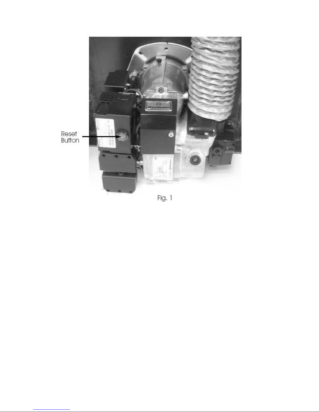
Wait for two minutes then press the manual reset button (coloured red –Fig 1) on the control box to reset.
SWITCHING THE BOILER OFF
The boiler can be switched off at anytime using one of the following:
-Turn the boiler control thermostat to the OFF position
-Switch the mains (electrical supply) to OFF
-Set the control system to OFF (e.g. Time Clock)
PLEASE NOTE: For longer periods of shutdown e.g. while away on holiday, switch OFF the mains
(electrical supply) and turn OFF the OIL supply.
If shutdown occurs during cold weather ensure boiler is protected against frost damage.
BURNER LOCKOUT
The burner has an independent control system (Burner Control Box); this includes a flame detector
(Photocell), which senses the presence of a flame. In the event of a flame failure, the burner control box
activates a second re-ignition sequence. Should the photocell not detect a flame presence within 15 seconds
the burner goes to LOCKOUT and shuts down.
Continued LOCKOUTS are a result of a fault in the operation of the boiler and can be attributed to
following examples:
-An interruption of the fuel supply.
-Electrical Supply Fault e.g. Extreme low voltage.
-Failure of a burner component.
-A fault within the heating system.
-Burner combustion not being correct.

The Burner Reset button on the Control Box illuminates to indicate that a lockout has occurred.
In the event of the Burner locking out, do not attempt to restart the Burner by pressing the Reset Button on
the Burner Control Box for at least 2 minutes. A Bi-metallic timer within the Control Box has a minimum
cooling time of 45 seconds thus the 2 minute interval will ensure that this Bi-metallic timer has cooled and is
therefore in a position where it may be reset.
RESTARTING AFTER LOCKOUT
When lockout has occurred, inspect for any obvious causes e.g. oil leaks. Also check the fuel line from the
tank to the boiler and that any oil shut off valve has not been inadvertently closed.
RESTART
-Check there is adequate oil in the storage tank.
-Check oil supply valves are open
-Switch on heating system (e.g. Time Clock)
-Press the Burner Reset Button on the burner Control Box, which will be illuminated. The Burner Reset
Button (illuminated)(Fig 1) will go out and the burner will commence the ignition start sequence. After
15 seconds the Burner should fire normally.
PLEASE NOTE: Should the Burner not start, the lockout indicator, on the Control Box/Burner Reset
Button will illuminate again.
- Wait at least 3 minutes and press the Burner Reset Button again.
Failure to start a second time indicates a fault requiring attention.
In the event of a second failure to start:
-Switch off electrical supply
-Call service engineer.
REGULATIONS
The installation of oil-fired boilers should comply with the following standards and codes of practice:
- BS5449 Forced circulation hot water heating systems for domestic use.
- BS5410-Part 1Oil installations up to 45kw
- BS7593 Water treatment of hot water central heating systems
- BS7671 Electrical Regulations
- Building Regulations Part 1L and J 2002 England and Wales, Part F Scottish Regulations and
Technical Booklet L Northern Ireland.
- OFTEC Codes of Practice Published or Recommended.
After installing, the system needs to be flushed with a cleanser like Fernox Heavy Duty Restore, for fast-
acting removal of lime scale, black sludge (magnetite) and other deposits from the boiler and the central
heating system. Then add a Fernox protector to give long-term protection of the central heating system
against internal corrosion lime scale formation.

WATER CONNECTIONS
Only two connections for the heating and hot water system on a standard condensing boiler:
1. Flow from top of boiler (Fig.2) and return to top of stainless steel heat exchanger (Fig.2).
2. The PVC pipe (fig 3) is 21.5mm Ǿ and should continue from the condensate trap in side the boiler
casing, which should be plumbed to an external source ensuring one of the following options:
- Internal waste drainage system - Soil/vent stack
- External Drainage system - External condensate absorption point
NOTE: condensate pipe work must fall at least 50mm per metre towards the outlet ensuring all joints are
leak proof.
WARNING: the condensate trap must be filled with water prior to starting the boiler to stop flue gases
escaping
BOILER LOCATION
Sound levels should be discussed with the householder, as some people may be sensitive to low noise levels
in a small room, as is may appear more annoying than in larger rooms. Please Note installation should take
into account of flue position (see diagram).
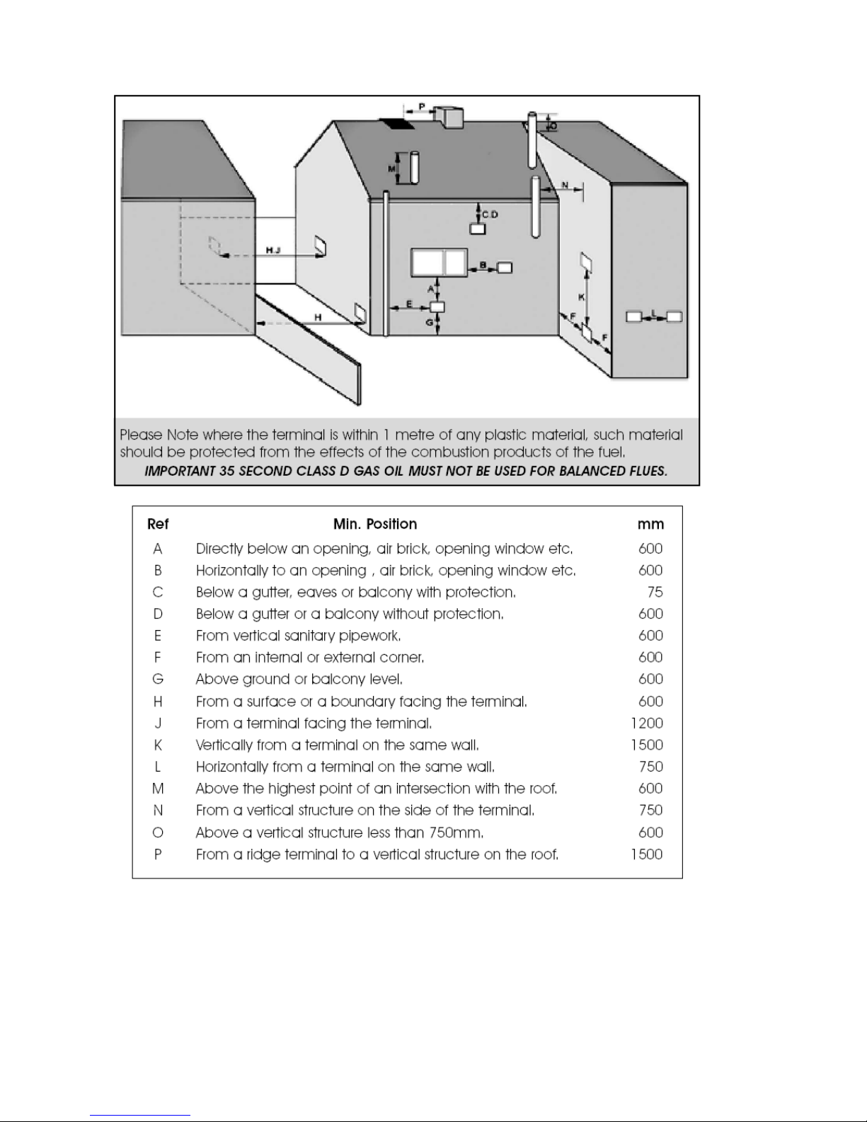
RECOMMENDED FLUE POSITION

OIL SUPPLY

A flexible oil pipe is supplied to connect the burner to the incoming oil supply pipe.
IMPORTANT NOTES:
-If sitting oil tank above burner height, use single supply pipe only.
-If sitting oil tank below burner height, use twin pipe supply or Tiger loop.
-Please refer to Burner Manual for conversion to oil pump for two pipe system.
ELECTRICAL ENTRY
The electrical supply to the boiler must be wired using a double pole-isolating switch 230v/50hz, fused 5
amps. The mains supply must be connected with the boiler dual stat, the supply will then continue down to
the burner control box. The burner is supplied with a three wire cable plug which allows disconnection for
maintenance.
General Data
Electrical Supply. 240w-50hz
Oil Supply Connection ¼” BSP
Fuel: 28 Second
High Limit Stat: Manual Reset
Maximum Control Thermostat Setting 85°C
Maximum Operating Pressure:
3 Bar –45psi –28m Static head room 92ft
Draught Limit
Min 12.5 Nm2–0.05” WG
Max 33.0 Nm2–0.12” WG

Note: 28 sec fuel must only be used on ECO Range Cookers & boilers
SERVICING INSTRUCTIONS
A competent service engineer OFTEC registered should be appointed on an annual basis.
Remove inspection door, burner and baffle assembly
Brush down the inside of the heat exchanger and vacuum out debris
Clean baffle assembly
Pull out inserts from stainless steel heat exchanger and clean before replacing.
Ensure stainless steel heat exchanger is thoroughly cleaned.
Empty and clean condensing trap (Fig.4)
Inspect and clean burner assembly, and replace with new nozzle (see burner manual)
Renew any insulation e.g. inspection door or inside base of heat exchanger
Reassemble baffles and replace inspection door.
Replace paper oil filters
Test oil pressure and test combustion.

BOILER SIZE
NO. OF INSERTS FROM L/H SIDE OF CONDENSER
REMAINING TUBES WITHOUT INSERTS
15/21 KW
10
6
1 SET OF BAFFLES
15/21 KW

BURNER SETTINGS
BOILER MODEL
15/21
MAXIMUM OUTPUT
Btu/hr
72000
Kw/hr
21
FACTORY SETTING
Btu/hr
63000
Kw/hr
18.5
NOZZLE SIZE
0.55 80 deg H
OIL PRESSURE
Bar
8
BURNER AIR
SETTING
7
SMOKE
0
CO2
%
11.5
FLUE GAS
TEMPERATURE
°C
80
WATER
INLET/RETURN
mm
22
WATER
OUTLET/FLOW
mm
22
CONDENSATE FLOW
mm
22 pvc rigid pipe
2MAX OPERATING
PRESS
Bar
2.5
BOILER EFFICIENCY*
SEDBUK A RATING
%
98
%
93.5
Electrical Power
230/240 V 50 Hz
Fuse
5 amp
SERVICE REQUIREMENTS
The boilers are serviced through an access panel at the front. A service access space of at least
700mm should be made available at the front of the boiler.
THE HEARTH
The temperature of the surface below the boiler is less than 85°C. If the floor under the boiler is of
combustible material, then protection such as steel should be fitted between the boiler and the floor.
Consideration should be given to the weight of the filled boiler; the floor must provide adequate
support. Please consult the building regulation for safe floor loadings.
CONTROL PANEL
The boiler control panel is factory fitted prior to despatch. The phials of the Control and High Limit
Thermostat are inserted into the pockets situated on the left hand side of the boiler heat exchanger.

ELECTRICAL ENTRY
The electrical supply to the boiler must be 230v/50hz, fused at 5 amps. Connection of the appliance and any
system controls, to the mains supply, must be a common isolator and must be fused at 5A maximum.
This must be fixed wired to a double pole-isolating switch that has a maximum contact separation of 2mm in
both poles. The isolator should be clearly marked showing its purpose, and preferably positioned close to the
boiler.
COMMISSIONING & SERVICING INSTRUCTIONS
A competent service engineer OFTEC registered should be appointed on an annual basis.
Isolate Power to the boiler
De-pressurise heating system and check expansion vessel pre-charge is the same as the cold fill
pressure, of the heating system. Expansion vessel pre-charge must not exceed 1.5 bar.
Remove inspection door, burner and baffle assembly
Brush down the inside of the heat exchanger and vacuum out debris
Clean baffle assembly
Pull out inserts from stainless steel heat exchanger and clean before replacing.
Ensure stainless steel heat exchanger is thoroughly cleaned.
Empty and clean condensing trap
Inspect and clean burner assembly, and replace with new nozzle (see burner manual)
Renew any insulation e.g. inspection door or inside base of heat exchanger
Reassemble baffles and replace inspection door.
Replace paper oil filters
Turn electrical supply to the boiler to ON.
This manual suits for next models
1
Table of contents
Other Eco Range Cooker manuals


