TEKNIX TKG104BL User manual

User manual
Teknix Support 01759 487823
Teknix Gas & Electrical
100 cm Range Cooker
TKG104BL / TKDF104BL
User manual

2
Dear User,
Our objective is to make this product provide you with the best
output which is manufactured in our modern facilities in a careful
working environment, in compliance with total quality concept.
Therefore, we suggest you to read the user manual carefully before
using the product and, keep it permanently at your disposal.
Note: This user manual is prepared for more than one model. Some
of the features specied in the Manual may not be available in your
appliance.
All our appliances are only for domestic use, not for commercial use.
Products marked with (*) are optional.
“THIS APPLIANCE SHALL BE INSTALLED IN ACCORDANCE WITH THE
REGULA TIONS FORCE AND ONLY USED IN A WELL VENTILATED SPACE.
READ THE INSTRUCTIONS BEFORE INSTALLING OR USING THIS APPLIANCE”
“Conforms with the WEEE Regulations."
3
CONTENTS
Important Warnings 4
Introduction Of The Appliance 7
Important Warnings 8
Electrical Wiring Scheme 9
Gas Mark Table 10
Gas Hose Passage Way 10
Installation Of Your Oven 11
Technical Features Of Your Oven 12
Injector, Gas Flow And Power Table 13
Reduced Gas Flow Rate Setting For Hob Taps 15
Reduced Flame Gas Cock Adjustment 15
Removal Of The Cathedral Burner 16
Description Of Oven 16
Using The Burner Groups 17
Using Oven Section 22
Cooking Time Table 25
Timer Operation 26
Cleaning And Maintenance Of The Oven’s Door 31
Maintenance And Cleaning 32
Installation Of The Oven Door 33
Accesories 34
Using The Grill Deector Sheet 35
If Your Oven Does Not Operate 36
Environmentally-Friendly Disposal and
Package Information 36

4
IMPORTANT WARNINGS
1.WARNING: To avoid electrocution, ensure that the
electrical circuit of the product is open before replacing
the lamp.
2.WARNING:Before touching the connection terminals,
all supply circuit should be disconnected.
3.WARNING:While operating the grill, the reachable
sections can be hot. Keep the children away.
4.WARNING:Any inadvertent cooking made with fats and
oils can be dangerous and cause re.
5.WARNING:Risk of re; do not store the food materials
on the cooking surface.
6.WARNING:If the surface is cracked, unplug the device
to prevent any risk of electric shock.
7.WARNING:During usage the reachable sections can be
hot. Keep the small children away.
8.WARNING:The appliance and its reachable sections
become hot during usage.
9.The setting conditions of this appliance is
indicated on the label. (Or data tag)
10.This appliance is not connected to a combustion
product discharge system.This appliance shall be
connected and installed as per the applicable
installation legislation. Consider the requirements
related with ventilation.

5
11.Using a gas hob will release humidity and combus-
tion products in the room where it resides. Especially
during when the appliance in use, ensure that the kitch-
en is well ventilated and retain the natural ventilation
holes or install a mechanical ventilation system. (Hood
on top of the oven) Sustained usage of the appliance
may require additional ventilation. For example open-
ing a window or if available, increasing the ventilation
level of a mechanical ventilation system.
12.The reachable sections can become hot when the
grill is used. Keep the small children away.
13.WARNING:The appliance is intended for cooking only.
It must not be used for other purposes like room heating.
14.There are additional protective equipment to
prevent inadvertent touching to the oven doors. This
equipment should be installed if there are children.
15.“This appliance should be installed as per
regulations and in well-ventilated location only.
Read the instructions before installing or operating
the appliance.”
16.“Before placing the appliance check the local
conditions (gas type and gas pressure) and ensure
that the settings of the appliance is appropriate.”
17.“These instructions are applicable for countries of
which symbols are indicated on the appliance. If the
country symbol is not available on the appliance,in
order to adapt the appliance to the conditions of such
country, the technical instructions should be read.”

6
18.“Do not operate the system for more that 15
seconds. If the burner does not ignite at the end of
15 seconds stop the operation of the system and open
the section door and/or wait for at least 1 minute before
igniting the burner.
19.Do not use steam cleaners to clean the appliance.
20.Before opening the oven door clean the remnants
on it. Before closing the oven door, let it cool.
21.NEVER try to extinguish a re with water, rst
disconnect the mains supply and then using, for
example a lid or blanket, cover the re.
22.Do not use hard and abrasive cleaning agents or
hard metal scrapers to clean the oven door glass as
they may scratch and shatter the surface.
23.After placing a dish, ensure that the door is rmly
closed.
24.Unless continuous supervision is provided, the
children of age 8 or below should be kept away.
25.Pay attention for not to touch the heating elements.
26.This appliance can be used by children aged from
8 years and above and persons with reduced physical,
sensory or mental capabilities or lack of experience
and knowledge if they have been given supervision or
instruction concerning use of the appliance in a safe
way and understand the hazards involved.
27. The appliance hasn’t been designed for operation
with an external time or a separate remote control system.

7
INTRODUCTION OF THE APPLIANCE
Note: The meaning of the symbols on the control panel of device is provided below.
Not every symbol is on every model; only take notice of the symbols on your device.
1
2
3
4
6
5
7
1. Burner Plate
2. Control Panel
3. LHS Grill
4. LHS Main Oven
5. Splash Back*
6. RHS Oven
7. Lower Part
1. Auxiliary Burner
2. Rapid Burner
3. Wok Burner
4. Digital Timer*
5. LHS Gril
6. LHS Main Oven
7. RHS Oven
8. Normal Burner
9. Normal Burner
10. Auxiliary Burner
11. Rapid Burner
1 2 3 54 6 7 8 9 10 11

8
IMPORTANT WARNINGS
Electrical Connection and Security
1. Your oven requires 26 Ampere fuse according to the appliance’s power.
If necessary, installation by a qualied electrician is recommended.
2.Your oven is adjusted in compliance with 220-240V AC 50/60Hz.
electric supply. If the mains are different from this specied value, contact
your authorized service.
3. Electrical connection of the oven should only be made by the sockets
with earth system installed in compliance with the regulations. If there
is no proper socket with earth system in the place where the oven will be
installed, immediately contact a qualied electrician. Manufacturer shall
never be responsible from the damages that will arise because of the
sockets connected to the appliance with no earth system.
4. Electrical cable should not touch the hot parts of the appliance.
5. For disconnection from the supply mains having a contact separation
in all poles that provide full disconnection, must be incorporated in xed
wiring in according with the wiring rules.
Gas Connection and Security
1. Before your appliance is connected to the gas supply, ensure that
the gas category and pressure specications shown in the data plate
corresponds with your gas supply. If necessary call authorized service
for adjusting to gas category.
2. This appliance shall be installed in accordance with the regulations
in force and only used in a well ventilated space. Read the instructions
before installing or using this appliance. In the interest of safety this
appliances must be installed and / or serviced by a competent person as
stated in the gas safety regulations current editions.
3. The appliance must not be installed in a room without a window or
other controllable opening. If is installed in a room without a door which
opens directly to the outside, a permanent opening is required. The air
circulation should be 2 m³/h per kW of burners.
4. The gas connection should be performed from the right or left. For
this reason, change the hose nozzle, plug and the seals.
5. Please use exible hose for gas connection.

9
6. If you make a connection with a exible metal hose, locate a seal
between the main gas pipes.
7. The inner diameter of the exible hose, which the butane hose
nozzle is connected, should be 6 mm for the house-type gas tubes.
The inner diameter of the exible hose, which the natural hose nozzle
is connected, should be 15 mm.The hose should tightly be tted to the
hose nozzle by squeezing with a clamp. The hose should be replaced
before its last expiry date.
8. Caution! Make the oven connection to the gas inlet valve, the hose
length must be short and be sure that there is no leakage. The exible
hose used should not be longer than 125 cm for safety.
9. Re-inspect the gas connection.
10. When placing your oven to its location, ensure that it is at the
counter level. Bring it to the counter level by adjusting the feet if
necessary.
DO NOT MAKE GAS HOSE AND ELECTRICAL CABLE OF YOUR OVEN GO THROUGH
THE HEATED AREAS, ESPECIALLY THROUGH THE REAR SIDE OF THE OVEN. DO
NOT MOVE GAS CONNECTED OVEN. SINCE THE FORCING SHALL LOOSEN THE
HOSE, GAS LEAKAGE MAY OCCUR.
ELECTRICAL WIRING SCHEME
220-240V~50/60Hz
H05 VV-F 3G 4mm²
Live
Phase
Neural
Earth
10
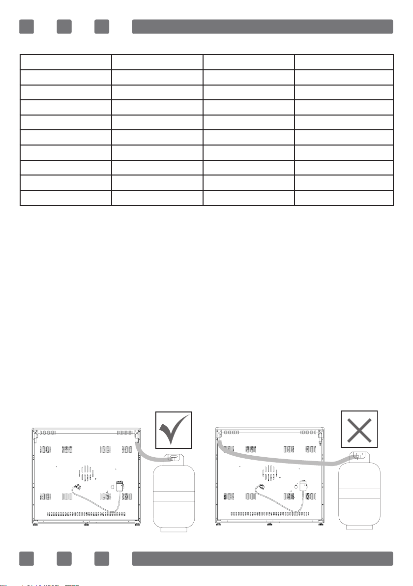
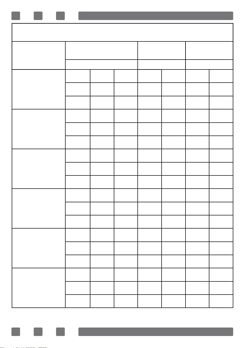
GAS MARK TABLE
Gas Mark Fahrenheit Celsius Description
1 275 140 Cool
2 300 150 ---
3 325 170 Very Moderate
4 350 180 Moderate
5 375 190 ---
6 400 200 Moderately Hot
7 425 220 Hot
8 450 230 ---
9 475 240 Very Hot
GAS HOSE PASSAGE WAY
1. Connect the appliance to the gas piping tap in shortest possible route
and in a way that ensure no gas leakage will occur.
2. In order to carry on a tightness and sealing safety check ensure that
the knobs on the control panel are closed and the gas cylindir is open.
3. While performing a gas leakage check, never use any kind of lighter,
match, cigarette or similar burning substance.
4. Apply soap bubble on the connection points. If there is any kind of
leakage then it will cause bubbling.
5. While inserting the appliance in place ensure that it is on the same
level with the worktop. If required adjust the legs inorder the make level
with the worktop.
6. Use the appliance on a level surface and in a well ventilated
environment.
Figure 1 Figure 2
11
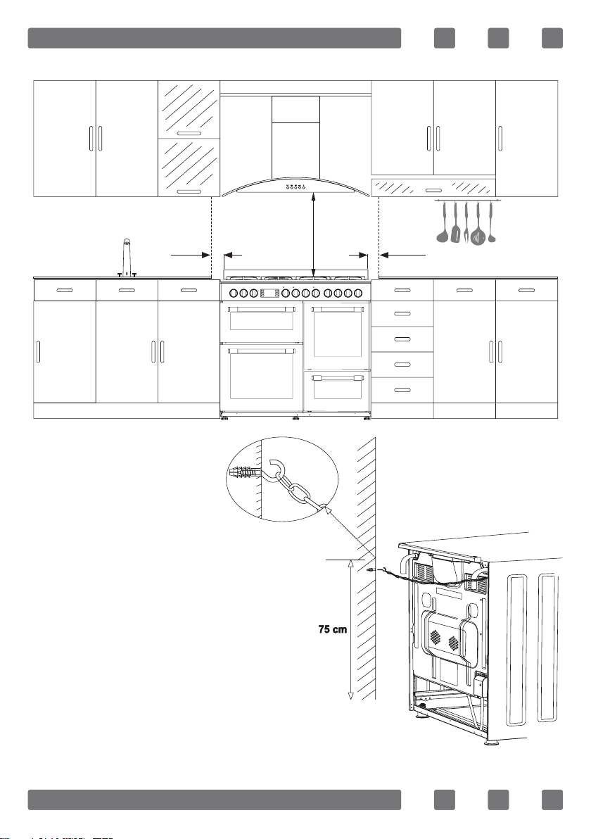
INSTALLATION OF YOUR OVEN
Chain Lashing Illustration
Before using the appliance, in order
to ensure safe use, be sure to x the
appliance to the wall using thechain
and hooked screw supplied. Ensure
that the hook is screwed into the wall
securely.
650mm min.
65mm min. 65mm min.
12
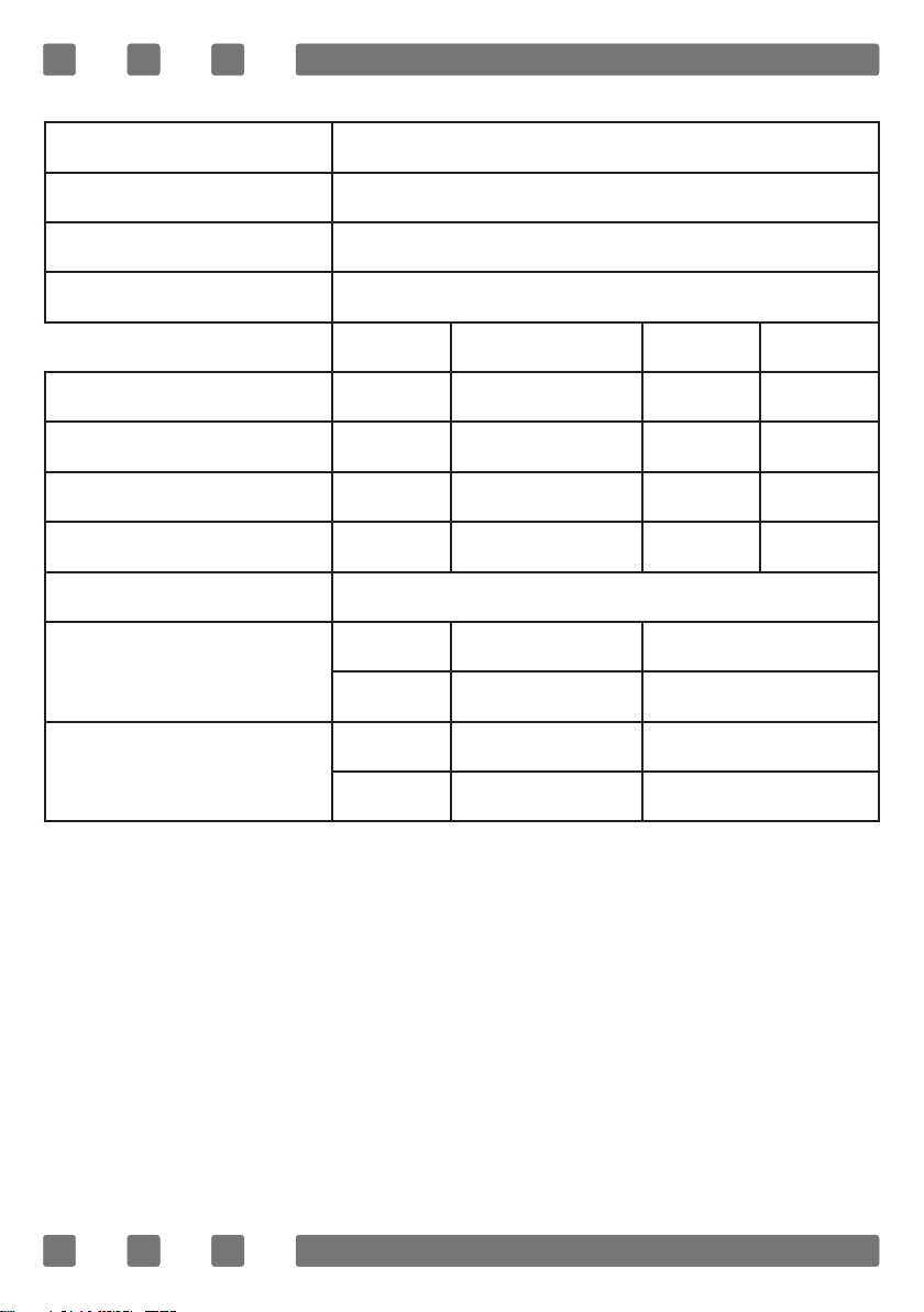
TECHNICAL FEATURES OF YOUR OVEN
Outer width 1000mm
Outer depth 600mm
Outer height 900mm
Lamp power 15-25W
Main Oven Grill Oven Top RHS Botton RHS
Bottom heating element 1200W --- 1000W 600W
Top heating element 1000W --- 800W 500W
Turbo heating element 1800W --- 1800W ---
Grill heating element --- 1400W --- ---
Supply voltage 220-240V AC 50/60Hz
Total electrical consumption
Type code MFR0/1702102E 5520W
Type code MFR0/1512122E 8320W
Total gas consumption
Type code MFR0/1701201G 20,1 kW, 1461 g/h
Type code MFR0/1512122E 10,75 kW, 782 g/h

13
RANGE COOKER
INJECTOR, GAS FLOW And POWER TABLE
BURNER
SPECIFICATIONS
G20,20 mbar
G25,25 mbar G20,25 mbar
Gas Natural Gas Natural
Wok
Burner
Injector 1,40 mm 1,28 mm
Gas Flow 0,333 m³/h 0,333 m³/h
Power 3,50 kW 3,50 kW
Rapid
Burner
Injector 1,15 mm 1,10 mm
Gas Flow 0,276 m³/h 0,276 m³/h
Power 2,90 kW 2,90 kW
Semi-Rapid
Burner
Injector 0,97 mm 0,92 mm
Gas Flow 0,162 m³/h 0,162 m³/h
Power 1,70 kW 1,70 kW
Auxiliary
Burner
Injector 0,72 mm 0,70 mm
Gas Flow 0,96 m³/h 0,96 m³/h
Power 0,95 kW 0,95 kW
Grill
Burner
Injector 0,92 mm 0,92 mm
Gas Flow 0,144 m³/h 0,144 m³/h
Power 1,50 kW 1,50 kW
Main Oven / RHS
Burner
Injector 0,97 mm 0,97 mm
Gas Flow 0,190 m³/h 0,190 m³/h
Power 2,00 kW 2,00 kW
14
RANGE COOKER
INJECTOR, GAS FLOW And POWER TABLE
BURNER
SPECIFICATIONS
G30,28-30 mbar
G31,37 mbar G30,50 mbar G30,37 mbar
LPG LPG LPG
Wok
Burner
Injector 0,96 mm 0,76 mm 0,96 mm
Gas Flow 254 g/h 254 g/h 254 g/h
Power 3,50 kW 3,50 kW 3,50 kW
Rapid
Burner
Injector 0,85 mm 0,75 mm 0,85 mm
Gas Flow 211 g/h 211 g/h 211 g/h
Power 2,90 kW 2,90 kW 2,90 kW
Semi-Rapid
Burner
Injector 0,65 mm 0,60 mm 0,65 mm
Gas Flow 124 g/h 124 g/h 124 g/h
Power 1,70 kW 1,70 kW 1,70 kW
Auxiliary
Burner
Injector 0,50 mm 0,43 mm 0,50 mm
Gas Flow 69 g/h 69 g/h 69 g/h
Power 0,95 kW 0,95 kW 0,95 kW
Grill
Burner
Injector 0,60 mm 0,55 mm 0,60 mm
Gas Flow 109 g/h 109 g/h 109 g/h
Power 1,50 kW 1,50 kW 1,50 kW
Main Oven / RHS
Burner
Injector 0,70 mm 0,65 mm 0,70 mm
Gas Flow 131 g/h 131 g/h 131 g/h
Power 2,00 kW 2,00 kW 2,00 kW
15
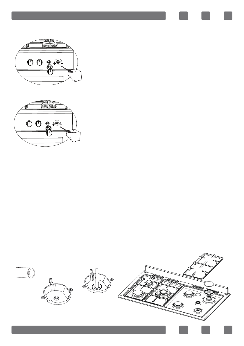
REDUCED GAS FLOW RATE SETTING FOR HOB TAPS
1. Ignite the burner that is to be adjustment
and turn the knob to the reduced position.
2. Remove the knob from the gas tap.
3. Use an appropriately sized screwdriver to
adjust the ow rate adjustment screw. For LPG
(Butane-Pro pane) turn the screw clockwise.
For the naturel gas, you should turn the screw
counter- clockwise once.
“The normal length of a straight ame in the
reduced position should be 6-7 mm.“
4. If the ame is higher then the desired
position, turn the screw clockwise. If it is
smaller turn anticolockwise.
5. For the last control, bring the burner both
to higt-ame and reduced positions and check
whether the ame is on or off.
Depending on the type of gas tap used in your appliance the adjustment
screw position may vary.
To adjust your oven acc. to the gas type, make the adjustment for re-
duced ame carefully by turning with a small screwdriver as shown below
on the screw in the middle of the gas cocks as well as nozzle changes.
(Figure 3 and 4)
REDUCED FLAME GAS COCK ADJUSTMENT
1. Please use driver with special head for removed and install nozzle
as (Figure 5).
2. Please remove nozzle (Figure 6) from burner with special nozzle
driver and install new nozzle. (Figure 7)
Figure 3
Figure 4
Figure 5
Figure 6
Figure 7
16
REMOVAL OF THE CATHEDRAL BURNER
The burner protection sheet is xed with two screws. As shown in
Figure 8, use a screwdriver to remove it. As shown in Figure 9, press
the spring clip in the direction of the arrow to remove the burner from
the slot. As shown in Figure 10, remove the injector in the bearing with
a socket wrench. In order to re-place the burner, apply the removal
process reversely.
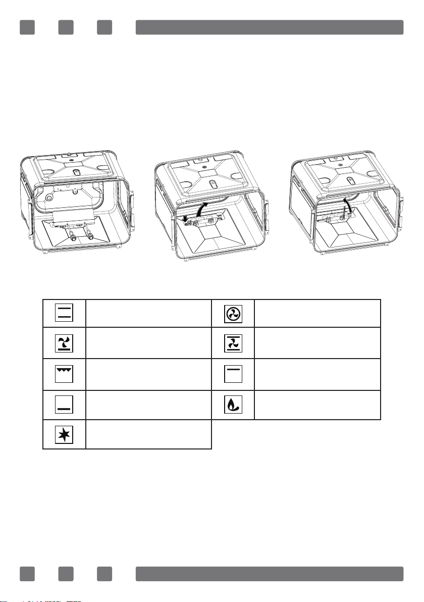
DESCRIPTION OF OVEN
THERMOSTAT KNOB; In order to operate the oven, thermostat must
be adjusted to desired temperature. Your thermostat has a feature of
adjustment to 40 - 240 degree.
Figure 8 Figure 9 Figure 10
Top + Bottom heating
element Turbo heating + Fan
Bottom heating element
+ Fan
Bottom + Top heating
elements + Fan
Grill burner / Grill heating
element Top heating element
Oven burner / Bottom
heating element Flame
Ignition Lighter

17
USING THE BURNER GROUPS
1. Closed Fully open Half open
2. If your oven has ignition system from push button switch please press
and turn gas valve open position and same time press ignition button.
3. Our gas ovens top and bottom burner working system is one by one.
When you want use your preference burner, before you must make press
the tap knob and wait nearly 5-10 second. Then you can to iname through
with automatic ignition system (optional) or match. You must wait 10-15
second after iname to have press by tap knob and after you can make
allow the knob. If you can not made this operation you must try again.
4. The cocks controlling the gas cookers have special mechanism.
In order to light the cooker;
5. Always press on the switch forward and bring it to ame symbol
by turning anticlockwise (left). All of the lighters shall operate and the
cooker you controlled shall light only. Keep the switch pressed until
ignition is performed.
6. In models with security system, when ame of the cooker is extin-
guished, control valve cuts off the gas automatically. For operate the burners
with gas security system you must make press the knob and turn antilock
wise. After the ignition (with optional automatic ignition system or match)
you must wait nearly 5-10 second for gas security systems activation.
7. Do not continuously operate the igniter for more than 15 seconds.
After 15 seconds, if the burner does not ignite, then stop and if you are
trying to ignite the oven then open the door and wait a minimum of one
minute before trying again. If the burner is extinguished for of the any
reason, close the gas control valve and wait a minimum of one minute
before trying again.
8. Before operating your hob please make sure that the burner caps
are well positioned. The right placement of the burner caps are shown
as below.
Figure 11 Figure 12

18
Pot Diameter
WOK Burner 26-32cm
Big Burner 22-26cm
Normal Burner 18-22cm
Small Burner 12-18cm
Gas Connection and Safety
1. For LPG (cylinder) connection, afx
metal clamp on the hose coming from LPG
cylinder. Afx an edge of the hose on hose
inlet connector behind the appliance by
pushing to end through heating the hose
in boiled water. Afterward, bring the clamp
towards end section of the hose and tighten
it with screwdriver. The gasket and hose
inlet connector required for connection is
as the picture shown below.
NOTE: The regulator to be afxed on LPG cylinder should have 300
mmSS feature.
2. Natural gas connection should be
done by authorized service. For natural
gas connection, place gasket in the nut
at the edge of natural gas connection
hose. To install the hose on main gas
pipe, turn the nut. Complete the con-
nection by making gas leakage control.
Gas hose and electric connection of the appliance should
not pass next to hot areas such as back of the appliance.
Gas hose should be connected by making wide angle turns
against breaking possibility. Movement of appliance whose
gas connection is made may cause gas leakage.
False False False True
Main Gas Pipe
Gasket
Hose Inlet Connector
Metal Clamp
Lpg Connection Hose
Main Gas Pipe
Gasket
Nut
Natural Gas Connection Hose

19
United Kingdom Type Gas Connection:
WARNING: The gas hose must not be clamped, bent ar trapped or come
into contact with hat parts of the product. There is the risk of explosion
due to damaged gas hose.
Ventilation Of Room
The air needed for burning is received from room air and the gases
emitted are given directly in room. For safe operation of your product,
good room ventilation is a precondition. If no window or room to be
utilized for room ventilation is available, additional ventilation should
be installed. However, room has a door opening outside, it is no needed
to vent holes.
Room Size Ventilating Opening
Smaller than 5m³ min. 100cm²
Between 5m³ - 10m³ min. 50cm²
Bigger than 10m³ no need
In basement or cellar min. 65cm²
l
6 5 / r
4
F
2
1. Gasket
2. Adapter
3. Gas (safety) hose
4. Valve with 90°outlet
5. Connection piece
6. Gas supply pipe

20
Using The Hobs
1. Auxiliary Burner
2. Normal Burner
3. Rapid Burner
4. Wok Burner
Large ame symbol indicates the highest cooking power and small ame
symbol indicates the lowest cooking power. In turned off position (top),
gas is not supplied to the burners.
Gas Breaking Safety Appliance
Against putting out to be taken place as
a result of liquid overow at upper burners,
safety appliance steps in and cut gas
immediately.
Wok Burner
As it possesses double ring ame system, it gives
homogenous heat distribution at the bottom of
cooking pot at high temperature. It is ideal for
short term and high temperature cooking. When
you want to use regular cooking pot on wok burner,
it is necessary that you remove wok cooking pot
carrier from oven.
1 2 3
3 4 2 1
Figure 13
Gas shut off safety
Figure 14
This manual suits for next models
1
Table of contents
Other TEKNIX Cooker manuals


Popular Cooker manuals by other brands


Hotpoint
Hotpoint HUE 62 Instructions for installation and use

Indesit
Indesit KP9F11S-G operating instructions

Centaur
Centaur CEN-WARM1220 operating instructions

Bosch
Bosch HCE743220G instruction manual

American Range
American Range ARSCT-244 installation manual

Kuppersbusch
Kuppersbusch KEH 650.0 Instructions for use and installation instructions

Tricity Bendix
Tricity Bendix SB230 Operating and installation instructions

Nordica
Nordica CUCINOTTA Instructions for installation, use and maintenance

Midea
Midea MFS90GSS Instruction

ILVE
ILVE UP60 User instructions, installation, maintenance

Creda
Creda HB49415 User instruction book

VESTEL
VESTEL VFSHI 90.60 user manual