Eco Range ECOFLAM MAX Operating manual

ECO RANGE
3 oven oil fired Cooker
For use in Great Britain and Eire (GB & IE)
Instructions for Use, Installation and
Servicing
This appliance must be installed in accordance with the regulations in force and only used in
an adequately ventilated space. Please read these instructions before installation and use and
retain for future reference.

1. Introduction
Thank you for choosing to purchase the 3 oven oil, balanced flue or conventional flued, Eco
Range cooker. Each cooker is manufactured and assembled by hand in our factory. This
appliance is designed to be capable of operating for long periods of time. With correct
installation and use your Eco Range cooker will provide many years of satisfactory service
and cooking enjoyment.
The appliance consists of two hotplates, 2 top ovens and a bottom oven or warming
compartment. The left sided hotplate is designed for more rapid heating suitable for frying
and boiling, whereas the right sided hotplate is more suitable for slower cooking and
simmering. Hotplate covers are provided to prevent heat losses when not cooking. The two
top ovens operate to provide a consistent temperature controlled environment for all your
cooking and baking needs. The bottom oven operates at lower temperatures and is suitable
for slow cooking or merely as a warming compartment, depending on the control setting.
These instructions detail how to get the most from your cooker, as well as fundamental
information on how the cooker shall be installed, maintained and used in a safe and practical
manner. It is important that some time is taken to read these instructions carefully
before installation and use of the appliance.
In order for the warranty to remain valid it is imperative that the appliance be installed in
compliance with all relevant national and regional regulations.
A competent heating and plumbing engineer must check/install the oil line for the cooker.
The warranty of your Eco Range Cooker applies to products sold in the UK and Eire
only. For products sold outside of these areas please contact the manufacturer for
details warranty authorisation.
2. Safety Instructions
Safety First:
This is a heating appliance; therefore it can become very hot when in service.
Young children and pets should be kept a safe distance from the cooker.
Ceiling mounted clothes dryers are strongly unadvised as they can present a fire hazard, this
also includes leaving towels on the handrail of the cooker.
Pans, especially chip pans, should not be left unattended on the Eco Range cooker.
Read and understand this booklet before installing and operating this appliance.
This appliance must be installed in accordance with the rules in force and used only in a
well ventilated space.
The appliance must only be installed and serviced by a suitably qualified and registered
technician.
The appliance shall not be altered in any way and only approved spare parts shall be
used. Failure to do so will invalidate any warranty or guarantee.

This appliance is very heavy and every care should be taken when trying to manoeuvre
it. Do not attempt to move or lift the appliance by the door handles, this could cause
damage to the doors and handles. It must be sited on a solid, level floor constructed in
accordance with any Building Regulations which may apply to the site.
It is important for the correct operation of this appliance that the installation space and
clearances around the appliance are in line with the specifications detailed in these
instructions.
Sufficient space should be available to allow the doors to be fully opened in excess of
120°from the closed position.
Ventilation openings on the side rear and front of the appliance should never be blocked
or restricted. see ventilation requirements
This appliance is capable of being operational at all times. Parts of the appliance will
become very hot, and remain hot for long periods. Only adults should operate this
appliance and only in accordance with the user instructions. Care should be taken when
using the cooker and the use of oven gloves is recommended when applicable. Children
should be supervised at all times if in the vicinity of the cooker.
In the interest of hygiene and safety the cooker should be kept clean at all times.
The cooker is designed for cooking foods only and must not be used for any other
purpose.
Always allow to cool before cleaning and carrying out maintenance work.
Do not use unstable or unsuitable saucepans and position handles away from the edge of
the hot plate. Thick, flat based saucepans are recommended for best results.
Do not place combustible materials onto the hot plate surfaces even when the cooker is
off.
Your Eco Range Cooker should be serviced at least once every twelve months. It is
impossible to service your cooker while it is hot, therefore DO NOT use your appliance
12 hours before a service is required.
Important:
The installer is responsible to ensure that all persons involved in the installation be provided
with the correct health and safety clothing when handling materials which are known to
cause potential harm.
Ceramic materials: Facemask and gloves must be worn, Contact with eyes, skin and
throat must also be avoided.
Fuels: Wear gloves –avoid ignition sources –Waste fuel should be disposed of
correctly, not via domestic waste water courses.
Fire cement: Wear gloves –wash hands.

Safety Notices and Regulations
The Building Regulations –Part J England and Wales –Part F section III Scotland –
Part L Northern Ireland –Part J Ireland.
BS5440 Parts 1 and 2 Installation of Flues and Ventilation.
D.M.2. Installation of Timber Framed Buildings.
Safety Document 635 The Electricity at Works Regulations.
BS7671 Requirements for Electrical Regulations.
REC Rules regarding PME Earthing (where applicable)
Warning:
Correct earthing must be provided for this appliance.
If in doubt seek advice from a qualified electrical engineer. Prior to carrying out any
work on the appliance switch off at the mains and remove the fuses from the fused spur
outlet and from the user control panel. Replace when works are complete. Always ensure
appliance is ‘electrically dead’ prior to working on the electrics.
3. Technical Specification
Appliance type - Cooker and Space heater
Cooker Burner System - Eco Flame Major
Fuel - 28 sec Kerosene
Country of Designation I.E & U.K
Mains supply - 230 Vac @ 50HZ from a dedicated fused spur.
Fuse rating - 5A
I.P Protection - 20
Load (Running) - 130W(Nominal)
Oil Pump working pressure - 115 psi/ 8 bar (Nominal)
Flue - Balance only or conventional flue.
Appliance max energy input - 14KW burn, 5kW hrs. as thermostatically controlled
Installation requirements - Must be installed in accordance with good practise
and as laid down by all relevant codes of practise
bysuitably qualified installers.
NB: See Installation Instructions within this manual
Balanced flue only - No further ventilation required.
4. Appliance Details
Overall Size -
Height (to hob)
910mm
Width (standard models)
1000mm
Hotplates –
Depth (to towel rail)
340mm diameter x 2
730mm

Ovens 3 of each –
Height
270mm
Depth
500mm
Width
345mm
Your cooker is fitted with a thermostatic control device. This operating system provides the
exact heat requirements selected (by the user) for cooking and reduces the overall oil
consumption. The user selects the desired cooking temperature and when the cooker
approaches the selected operating temperature the thermostatic control operates to turn off
the burner flame to maintain a steady temperature. The control knob on the device is marked
which relates to a particular temperature setting of the top oven.
4.1
Using your hotplates
Your appliance has two hotplates, with a joint hotplate in the middle, protected with two
insulated lids which should remain in a closed position when not using the hotplate. The lids
can be raised independently if only using one hot plate. The hot plate temperature is
dependent on the setting of oven temperature. The higher the temperature in the ovens, the
hotter the hotplate will become.
The design of the hot plates is such that the left hand side will become the hottest, making
this suitable for deep fat frying, shallow frying and boiling.
The surfaces of the hotplates are ground flat and it is therefore recommended that all
utensils used have a solid, flat base to come in complete contact with the hot plate for
efficient results.
4.2
Using your Ovens
Your appliance has 2 ovens. The thermostatic dial in the top oven door provides an
indication to the top oven temperatures. This thermometer reading will reduce quite
dramatically when the door is opened and only recover slowly when the door is closed. This
occurrence does not mean that the oven temperature has reduced. The bottom oven is
warmed by the underside of the oven above. Depending on the control device setting and
operational time, this oven will generally operate some 85 –90°C below the top ovens. It
may be used for small food cooking, biscuits, cakes etc but it is best used as a warming
compartment.
4.3
Overheatthermostat
The cooker is protected by an overheat thermostat designed to shut down the burner if a
fault occurs leading to excessive oven temperatures. The overheat thermostat is located
below the control device, inside the lower left compartment. To reset, unscrew the
protective cap and press the button.
NOTE: If overheat reset occurs more than once contact your service technician.

4.4
Cleaning your cooker
CAUTION: Cleaning of the Eco Range Cooker should only be carried out when the
appliance has cooled down.
The Eco Range cooker should be wiped over daily with a damp soapy cloth. The enamel
should then be dried and polished with a soft dry cloth to avoid streaking. Any spillages
should be wiped up immediately to prevent hardening of deposits which would make
removal difficult at a later stage.
The hot plates can be kept clean by using a light suede wire brush and gently scrubbing the
plates, taking care not to damage the surrounding enamel. Spillages inside the ovens can
become carbonized at high temperatures, therefore the ovens should be cleaned at regular
intervals with a stiff brush. The surfaces of the oven are natural, therefore to prevent
oxidation dry all surfaces after cleaning.
4.5
Routine servicing / maintenance
All oil appliances require regular servicing by a qualified technician. It is recommended that
your cooker is serviced at least once a year. This will ensure your cooker remains fully
functional and in a safe condition.
5.1 Delivery and Transport
Your Eco Range Cooker is an extremely heavy and solid appliance. When attempting to
move or transport your cooker please take into consideration these points:
External –In Vehicle –Ensure unit is securely held by ropes and handled carefully by
qualifiedpersonnel.
Internal
Remove all objects from your path, including rugs and breakables.
It is often easiest to unhinge a door in the case that it is too narrow, it also stops damage
being applied to the cooker, the property and injuring people.
The plinth on the cooker is strong and sturdy enough to withhold the unit being moved on
rollers, byremoving the oven doors you can also create useful handholds.
IMPORTANT:
The top plate is unable to manage the weight of the cooker so should never be moved
or lifted in this way.
Damage can be caused to the cooker and to persons by using inadequate objects to
lever or move the object.
Difficult terrain, including steps, should not be attempted without adequate
manpower and proper precautions.
The supplier of your new ECO Range Cooker can provide you with an authorised engineer
to attend site, strip the appliance and rebuild in the correct location.

The warranty will become invalid if you strip and rebuild the cooker yourself.
5.1
SiteConsiderations
1.
Sufficient space for appliance, so that access for service and maintenance purposes
can be easily attained.
2.
Provision of a satisfactory flue/chimney/cowl.
3.
A sold non-combustible hearth capable of supporting the appliance.
4.
Adjacent to the cooker then should be no combustible walls or surfaces.
5.
The cooker must stand against an outside wall so that there is a supply of unrestricted
air to the burner.
6.
If the cooker is to be placed within an inglenook, allow a minimum of 1.5 meters
height clearance for comfortable operation.
7.
Units and other work tops should be given enough space, allow 25mm for kitchen
units and 10mm for worktops, 3mm should be given for granite and composite stone.
8.
The cooker must not be built in, especially the top plate and front plate which must
be removed for maintenance.
6.0 Balanced Flue
A balanced flue allows the cooker to be placed against an outside wall, with either rear or
top outlet concentric flue.
Maximum length of rear flue: 500mm
Maximum length of top outlet flue: 300mmvertical
500mmhorizontal
The surrounding area must be taken into consideration, as strong winds may affect flue
performance.
Balanced flue units are supplied with the following components:
1 no. Outer flue pipe 5” (exhaust outlet)
1 no. Air pipe 3” (air intake)
1 no. Flue terminal
1 no. Heatproof silicon
4 no. Stainless steel self-trapping screws
1 no. Oven vent pipe with tee
Instructions for installation:
1.
A suitable position for the range must be taken into consideration before attempting
to install or move the appliance. See section 5.1 for site considerations.
2.
Mark the positions for the flue and oven vent, it is important to confirm all
measurements byphysically measuring the appliance.
3.
Push oven vent through hole and manoeuvre cooker into position. After the cooker
has been moved to the correct position, tighten the compression fitting so that there is
a 3/5º drop from appliance to outside termination.
4.
Cut the pipes to the correct length.

5.
With the supplied tape and silicon make a seal on the inner and outer pipes. Push into
the cooker, whilst making sure no excess sealant has leaked that may block the
cooker
spigots. Ensure minimum of 3º drop.
6.
With suitable material make a good flue hole.
7.
Fit the terminal to the pipes whilst ensuring the inner pipe has adequate clearance
between terminal end and outlet (min. 50 mm). Secure terminal with supplied screws
and heatproof silicon.
8.
The oven vent must then be cut to the correct length, solder tee to pipe with outlets
top and bottom. It is vital that there are no bends in the oven vent.
Warranty on the Cooker structure & castings: 5 Years (Excludes labour)
Warranty on Burner and Controls: 2 Years
CONDITIONS OF WARRANTY:
1. Boiler MUST BE installed by a representative of the company or OFTEC registered engineer, if not
permission will be required by building control.
2. Burner MUST BE commissioned after installation by an OFTEC registered engineer.
3. Burner MUST BE serviced every 24 months after installation by an OFTEC registered engineer.
IMPORTANT CHANGES TO BOILER MANAGEMENT:
Annual Service –This is very important in order to keep the flue ways clean and ensure the boiler is
correctly set.
SWITCHING THE COOOKER OFF
The burner can be switched off at anytime using one of the following:
-Turn the oven control thermostat to the OFF position
-Switch the mains (electrical supply) to OFF
-Set the control system to OFF (e.g. Time Clock)
PLEASE NOTE: For longer periods of shutdown e.g. while away on holiday, switch OFF the mains
(electrical supply) and turn OFF the OIL supply.

BURNER LOCKOUT
The burner has an independent control system (Burner Control Box); this includes a flame detector
(Photocell), which senses the presence of a flame. In the event of a flame failure, the burner control box
activates a second re-ignition sequence. Should the photocell not detect a flame presence within 15 seconds
the burner goes to LOCKOUT and shuts down.
Continued LOCKOUTS are a result of a fault in the operation of the boiler and can be attributed to
following examples:
-An interruption of the fuel supply.
-Electrical Supply Fault e.g. Extreme low voltage.
-Failure of a burner component.
-Burner combustion not being correct.
The Burner Reset button on the Control Box illuminates to indicate that a lockout has occurred.
In the event of the Burner locking out, do not attempt to restart the Burner by pressing the Reset Button on
the Burner Control Box for at least 2 minutes. A Bi-metallic timer within the Control Box has a minimum
cooling time of 45 seconds thus the 2 minute interval will ensure that this Bi-metallic timer has cooled and is
therefore in a position where it may be reset.
RESTARTING AFTER LOCKOUT
When lockout has occurred, inspect for any obvious causes e.g. oil leaks. Also check the fuel line from the
tank to the boiler and that any oil shut off valve has not been inadvertently closed.
RESTART
-Check there is adequate oil in the storage tank.
-Check oil supply valves are open
-Switch on heating system (e.g. Time Clock)
-Press the Burner Reset Button on the burner Control Box, which will be illuminated. The Burner Reset
Button (illuminated)(Fig 1) will go out and the burner will commence the ignition start sequence. After
15 seconds the Burner should fire normally.
PLEASE NOTE: Should the Burner not start, the lockout indicator, on the Control Box/Burner Reset
Button will illuminate again.
- Wait at least 3 minutes and press the Burner Reset Button again.
Failure to start a second time indicates a fault requiring attention.
In the event of a second failure to start:
-Switch off electrical supply
-Call service engineer.
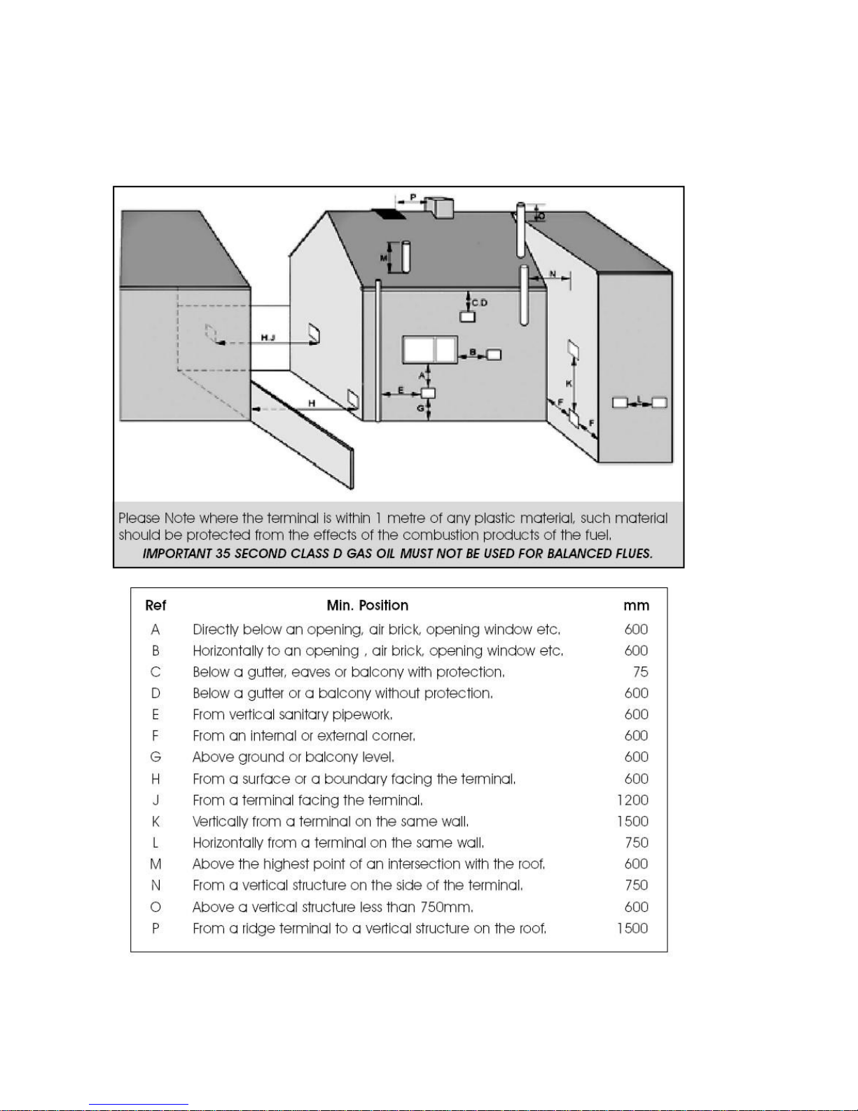
REGULATIONS
The installation of oil-fired cooker should comply with the following standards and codes of practice:
-BS5410-Part 1Oil installations up to 45kw
-BS7671 Electrical Regulations
- Building Regulations Part 1L and J 2002 England and Wales, Part F Scottish Regulations and
Technical Booklet L Northern Ireland.
- OFTEC Codes of Practice Published or Recommended.
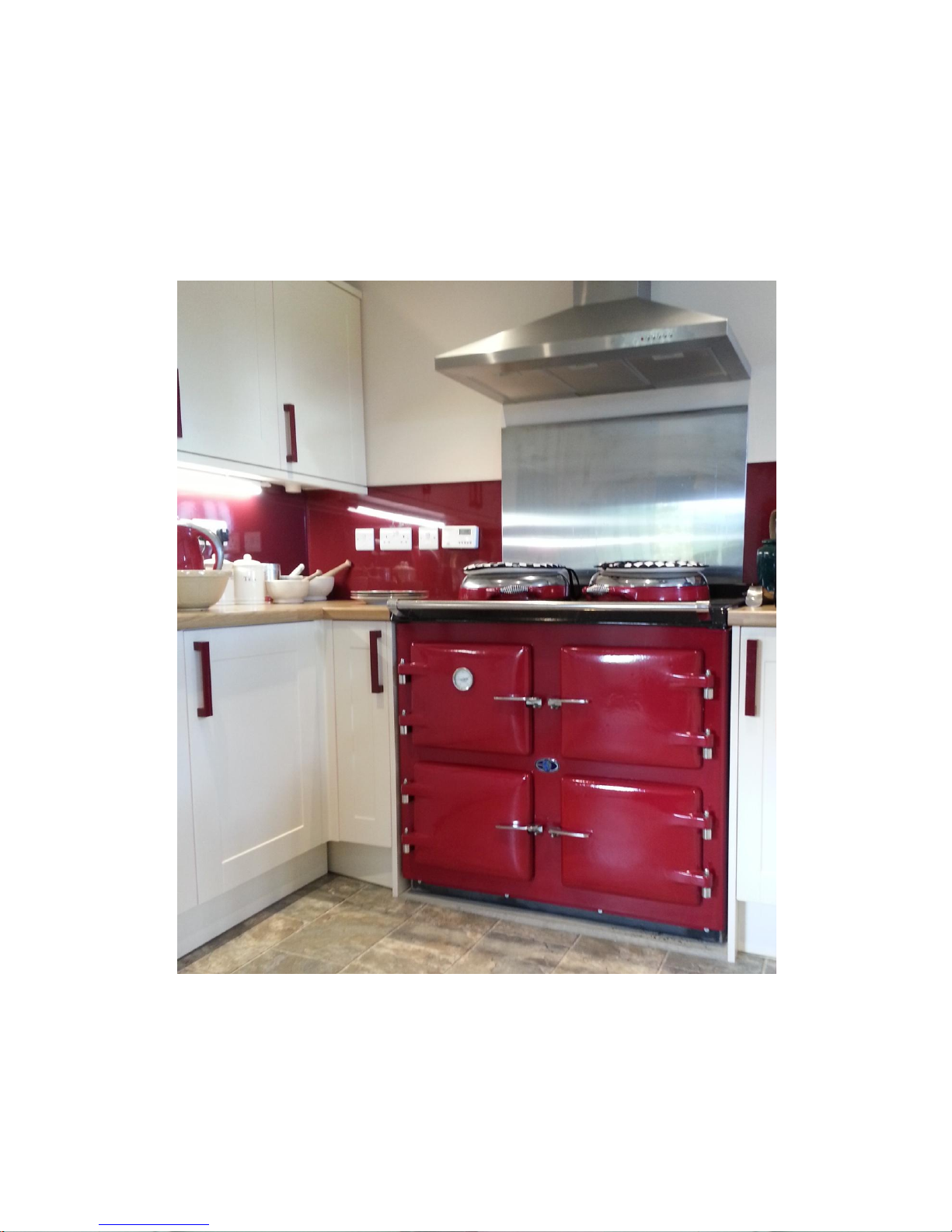
COOKER LOCATION

Sound levels should be discussed with the householder, as some people may be sensitive to low noise levels
in a small room, as is may appear more annoying than in larger rooms. Please Note installation should take
into account of flue position (see diagram).
RECOMMENDED FLUE POSITION

OILSUPPLY
BOILER
TYPICAL SYSTEM SHOWN
Diagrams of 1win pipeoilsupply sys1ems
,-BOILER
f
_FIREVAL.:\IESENSOR
,/
/
/
I ALTERNATIVEFILTER POSITION
/
BOILER
OILTANK ..!.
PlastictankshJwnsteel
tankalsosui1abla
OILTANK
Plastictankshown
steeltankalsosuitable
?-
I
I
VENT
-J,.
/
il!,.
I
:r •
PAPERELEMENTFllJER
_j'//
FIREVALVE _....•·
-
.-
•
\
I
OILFULL LEVEL
Plaslictank-shown
Stealtankalso-su-:tabfe
Single PipeOilSystem

A flexible oil pipe is supplied to connect the burner to the incoming oil supply pipe.
IMPORTANT NOTES:
-If sitting oil tank above burner height, use single supply pipe only.
-If sitting oil tank below burner height, use twin pipe supply or Tiger loop.
-Please refer to Burner Manual for conversion to oil pump for two pipe system.
ELECTRICAL ENTRY
The electrical supply to the cooker must be wired using a double pole-isolating switch 230v/50hz, fused 5
amps or standard plug/socket. The mains supply must be connected via the clock, the supply will then
continue down to the burner control box. The burner is supplied with a three wire cable plug which allows
disconnection for maintenance.
General Data
Electrical Supply. 240w-50hz Oil Supply Connection ¼” BSP
Fuel: 28 Second High Limit Stat: Manual Reset
Maximum Control Thermostat Setting 250°C
Draught Limit Min 12.5 Nm2 –0.05” WG
Max 33.0 Nm2 –0.12” WG
Note: 28 sec fuel must only be used on ECO Range Cookers & boilers
SERVICING INSTRUCTIONS
A competent service engineer OFTEC registered should be appointed on an annual basis.
Remove inspection door, and burner
Inspect and clean burner assembly, and replace with new nozzle (see burner manual)
Replace paper oil filters
Test oil pressure and test combustion.
BURNERSETTINGS
BURNER MODEL
ECOFLAM MAX
MAXIMUM OUTPUT
Btu/hr
45000
Kw/hr
14
FACTORY SETTING
Btu/hr
48000
Kw/hr
14
NOZZLE SIZE
0.3 60DEG S
OIL PRESSURE
PSI
100

SMOKE
0
CO2
%
9 - 11.5
FLUE GAS
TEMPERATURE
°C
185
Electrical Power
230/240 V 50 Hz
Fuse
5 amp
THE HEARTH
The temperature of the surface below the boiler is less than 100°C. If the floor under the boiler is of
combustible material, then protection such as steel should be fitted between the boiler and the floor.
Consideration should be given to the weight of the cooker, approx 450kG; the floor must provide
adequate support. Please consult the building regulation for safe floor loadings.
CONTROL PANEL
The boiler control panel is factory fitted prior to dispatch.
ELECTRICAL ENTRY
The electrical supply to the boiler must be 230v/50hz, fused at 5 amps. Connection of the appliance and any
system controls, to the mains supply, must be a common isolator and must be fused at 5A maximum.
This must be fixed wired to a double pole-isolating switch that has a maximum contact separation of 2mm in
both poles. The isolator should be clearly marked showing its purpose, and preferably positioned close to the
boiler.
COMMISSIONING & SERVICING INSTRUCTIONS
A competent service engineer OFTEC registered should be appointed on an annual basis.
Isolate Power to the boiler
Inspect and clean burner assembly, and replace with new nozzle (see burner manual)
Replace paper oil filters
Turn electrical supply to the boiler to ON.
Set burner pump pressure.
Allow time for the cooker to reach normal operating temperature.
Check the smoke reading.
Measure the Co2
Measure net flue gas temperature.
Warranty Registration
Guarantee
Your cooker now has a one year parts and labour guarantee and a further four year parts guarantee, it is the
responsibility of the installer to ensure that the cooker is properly commissioned. This must be by a qualified
technician. It is essential that the commissioning procedures detailed in this manual are carried out by a

qualified engineer, using recognised test equipment and that the regulation of the latest edition of BS 5410,
Part 1 is read and fully adhered to. The following warranty registration page should be completed by the
installer, signed by the customer and returned to ECO Range Cookers. The installer should re-check the
cooker and ensure everything is completely satisfactory before demonstrating the operation of the cooker to
the householder.
WARNING: Failure to return the Warranty Registration will render the guarantee null and void this
complete manual must be left with the householder.
COOKER WILL NOT START
Check if mains electricity supply is reaching boiler control panel, making sure control thermostat is turned
on and time clock is calling for heat. Mains indicator green should be illuminated. If green light is not
illuminated and fuse has been checked then heating system charge may be low, check black needle on
pressure, located inside boiler cabinet (top right hand side) is reading 1 bar or more. If not depressurised,
refer to fault diagnosis.

WARRANTYREGISTRATION
Appliance Model Serial Number
Date of Commissioning:
CUSTOMERDETAILS
Customer Name: (in BLOCK CAPITALS)
Address:
Town:
County:
Postcode:
Customer Signature
COMMISSIONING TECHNICIANSDETAILS
Technician’s Name: (in BLOCK CAPITALS)
Technician’s Competent Persons
OFTEC Registration Number
Address:
Town:
County:
Postcode:
Technician'sSignature
Cooker
Burner pressure psi
CO2%
CO ppm
FGT
Electrical Safety
Before leaving Eco Range Cookers this unit was: Checked By:
Date:
Please return this completed page to:
Eco Range cookers
60 Wincheap
Canterbury
Kent
CT1 3RS

SERVICERECORD
Appliance Model Serial
Number
Date of Service:
ENGINEER DETAILS
Engineer's Name: (in BLOCK
CAPITALS)
Engineers Registration
Number
Engineer's Signature
Date
COMBUSTION ANALYSIS
Cooker
Pump pressure
CO2 %
CO ppm
Flue Gas
Temperature
CO/CO2
Efficiency %
Engineer's
Comments:
Jet Changed
Yes
PARTSREPLACED:
Jets should be changed annually.
Table of contents
Other Eco Range Kitchen Appliance manuals