Eco Sensor ES701 User manual
© Eco Heat Equipment – Oct 2016 1 of 2
ES701 Passive Infrared (PIR) IP65 Motion Sensor User
Manual
General
The ES701 PIR IP 65 motion sensor is ideal for outdoor or high humidity applications,
such as outdoor lights and bathrooms loads. The sensor has an extruding screw
that can easily be installed directly onto a light fixture.
If, after reviewing this guide, you require additional information or assistance
or www.ecosensor.co.za.
Technical Specifications
§Voltage: 220 – 240V/AC
§Frequency: 50/60Hz
§Load: Incandescent max: 450W
Fluorescent max: 275W
LED max: 150W
§Detection Angle: 360 °
§Detection Range: 1.4 m- 8m radius (dependent on mounting height)
§Light level: 10 – 50 LUX and 24H
§Time setting: 10 seconds – 60 minutes
§Dimming Level: 0%, 10%, 20% and 30%, Dimming Function Off
§Installation height: 2.5 - 7m max
§Working temperature: -10°C to 35°C
§IP Rating: IP65
§Dimensions: Length: 129.6mm (149mm with connector)
Width: 36.4mm
Height: 28mm
Connector inside diameter: 17.1mm
Connector outside diameter: 20.4mm
Safety
Any incorrect use or installation procedure not recommended by the
manufacturer may cause fire, electrical shock or injury to persons.
Box Contents
Your box should contain the following items:
§Sensor
§Silicone Washer
§M20 Nut
§2 x spacers
WARNING:
Controlling a load in excess of the specified ratings will damage the unit and lights
and could pose risk of fire and electric shock.
Do not install this unit to control a power socket.
Installation Instructions
WARNING: ALL WIRING MUST BE DONE IN ACCORDANCE WITH NATIONAL AND
LOCAL ELECTRICAL CODES AND STANDARDS.
Note: motion sensors respond to rapid changes in temperature so care should be
taken not to mount the device near a climate control source (i.e. heaters or air
conditioners). Hot or cold draughts will seem like body motion to the sensor and will
trigger the device. Recommended distance from climate control devices is 2m.
1. Turn power off at circuit breaker or fuse
2. Connect wires as per diagram
3. Sensor can be secured onto light fitting
4. Restore power at circuit breaker or fuse
Sensor calibration:
Note: Allow up to 1 minute for the motion sensor to recalibrate after it has been
connected for the very first time. This is only necessary during installation or when
the mains supply is disconnected.
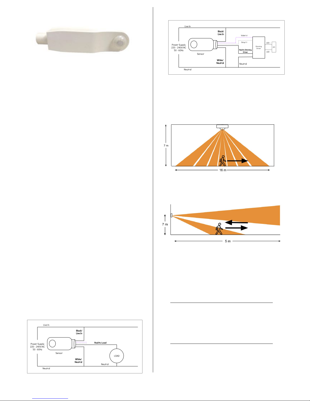
Installation wire diagram – NO DIMMING DIRIVER
Installation wire diagram – DIMMING DIRIVER
Operation and Field of View
The motion sensor detects motion within its coverage area and controls the
associated lighting connected to the sensor. The passive infra red (PIR) sensor is
sensitive to the heat emitted by the human body. In order to trigger the sensor the
source of heat must move from one zone of detection to another. The device is
most effective in sensing motion across its field of view and less effective sensing
motion towards or away from its field of view**.
Sensor detection range from side: large motion* across detection zone
*Detection range for large motion at 2.8m height: 14m (diameter).
**Detection Range will decrease with approximately 35% with movement towards
or away from the sensor
Sensor detection range: large motion* towards/away sensor
Motion Sensor Settings and Adjustments
The motion sensor is a Passive Infra Red (PIR) type electronic occupancy detector,
which in turn switches the lights when connected to the motion sensor. There are
five adjustments (three if the dimming function is not used) that can be made to
influence the operation of the motion sensor:
1. RANGE/SENSITIVITY: motion detection range
2. STAND-BY TIME: time delay after motion until shut off/dimming
3. LUX/LIGHT: level of ambient light sensitivity
4. DIMMING LEVEL: level of dimming required*
5. DIMMING TIME: time delay after motion until shut off *
* Only applicable if grey and violet wires are connected to dimming driver
The five adjustments settings are as follows:
Detection/Sensitivity range: 20%, 50%, 75%, 100%
Stand-by time setting range: 10 sec, 1 min, 5min, 15min, 30min, 60 min
Lux (light) sensitivity: 24H,10 LUX, 30LUX
Dimming level: *0%, 10%, 20%, 30%
Dimming time: *24H, 1 min, 30min, 60min, 24H
* Only applicable if grey and violet wires are connected to dimming driver
Motion Sensor Adjustments
The motion sensor’s settings is adjusted using the ES-REMD remote control.

© Eco Heat Equipment – Oct 2016 2 of 2
Mandatory Remote Control
The sensor’s red LED will flash 3 times to
confirm each setting applied
ON=Always on. After about
20min turns to “AUTO” mode.
OFF=Always off. After about
20min turns to “AUTO” mode.
Automatic ON/OFF
Reset: Resets unit for settings
setup and to default settings.
Test mode: Light level will not
influence the operation in this
mode. Use to test and setup
detection range.
Automatic reading and
saving of the actual light
level
Range/Sesitivity settings: (10%
to 100%)
Stand –by time settings: (10
secs to 60 mins)
Lux/Light settings (10 to 50 Lux
and 24H).
Recommendation: rooms
without daylight 24H.
Dimming Level: (0% to 30%)
Dimming Time: (1min to
60Min)
Steps to setting the motion sensor:
Step 1 – Ensure sensor is active
Press the “ON” button.
Step 2 – Set sensor in AUTO mode
Press the “AUTO” button.
Step 3 – Reset the sensor
Press the “RESET” button.
Resets the sensor for settings setup and to default settings:
Detection/Sensitivity range: 100%
Stand-by time setting range: 5min
Lux (light) sensitivity: ☼(24H)
Dimming level: * 20%
Dimming time: * 60min
* Only applicable if grey and violet wires are connected to dimming driver
Step 4 – Set the Sensitivity/range
Press desired Sensitivity button to set the range.
100% = 7m radius at 2.8m height
50% = 3.5m radius at 2.8m height
Step 5 – Set the Stand-by time delay
Press desired Stand-by time button to set the delay.
Note: If sensor is connected directly to a load setting sets delay after movement
until shut off.
Note: If sensor is connected to a dimming driver setting sets the delay after
movement until dimming.
NOTE: All the time intervals are within approximately 10 seconds of the stated time
out interval.
Step 6 – Set the LUX/light level
Press desired LUX button to set the light level.
Note: Dusk or dawn is approximately 50LUX
Step 7 – Set the Dimming level
Press desired Dimming Level button to set the dimming level.
Note: If sensor is connected directly to a load press the “0” button.
Step 8 – Set the Dimming time
Press desired Dimming Time button to set the shut off dealy
Note: If sensor is connected directly to load press the “24H” button.
Note: If sensor is connected to a dimming driver setting sets the delay after
movement until shut off.
NOTE: After pressing a settings button the load will switch off and back on after a
few seconds if ambient LUX levels is below current LUX level setting on the sensor.
The sensor’s red LED will flash 3 times to confirm each setting applied and stored.
OTHER CAUTIONS:
Disconnect power when working on electrical outlets or components.
Do not push on the surface of the lens.
Cleaning
Carefully wipe sensor with a soft damp cloth. Do not apply pressure to the lens.
Recycling
Please recycle all packaging material that came with the motion sensor.
Warranty
The sensor has a three (3) year warranty after the date of the original purchase.
Please keep your original receipt, as this will be required for any claims under this
warranty. The warranty is a strictly carry in policy. (The sensor/s has to be returned
to Eco Heat offices for a claim to be processed).
The warranty does not cover:
§damage from misuse,
§neglect or abuse,
§products that have been modified in any way,
§shipping and handling cost associated with the product,
§damage resulting from accidents, lightning, fire, water, power surges,
natural disasters and/or incorrect installation
For more information, view the Return/Refund Policy at www.ecosensor.co.za.
Trouble Shooting
Malfunction
Possible Cause
Remedy
The unit will
not switch
“on”
a. No mains power
b. No movement is
detected (in detection
zone)
c. Wrong LUX/LIGHT level
setting
d. Electrical circuitry faulty
e. Electrical Installation not
done correctly
f. Unit may be faulty
a. Check mains power is on
b. Move towards the unit (in
detection zone) or increase the
detection range settings
c. Adjust setting on the LUX/LIGHT
settings
d. Refer to the ‘Electrical
Installation’ section to ensure
correct installation
e. Have a certified electrician
disconnect and test the unit
f. Contact Eco Heat Equipment
Unit stays
“on”
permanently
g. Continuous movement in
detection zone
h. The sensor is not
mounted correctly for
reliable operation
i. Wrong LUX/LIGHT level
setting
j. Time setting control is set
too far
k. Unit may be faulty
l. Unit is mounted on a
vibrating or moving
structure.
g. Check detection range setting
and reduce detection range
sensitivity
h. Check detection range setting
and mounting procedure
i. Adjust setting on the LUX/LIGHT
settings
j. Adjust the time setting control
k. Contact Eco Heat Equipment
i. Move unit to a fixed mounting
structure, check mounting
procedure
Due to minor improvements in design or otherwise, the product you purchase
may differ from the one shown in this leaflet. For more information or advice on
this or any other Eco Heat Equipment products, visit www.ecosensor.co.za or
phone +27 (0)861 999 887.
Indemnity: The Author, and supplier, shall not be held liable for any loss, injury or
damage, of whatsoever nature, whether consequential or not, either contractual
sustained to, or caused by, or which may arise through the use of any comments,
suggestions, circuitry, services or equipment offered for purchase. The User,
indemnifies the author and supplier, and agrees not to hold him/her responsible
for any damages, losses and/or liabilities (including legal costs on a scale as
between attorney and user) arising from, or through the use of circuit diagrams,
equipment and services, whether such circuit diagrams, equipment and services
were used with the consent of the User or not. All risks attached to the use of
circuit diagrams, equipment and the connection thereof to the User’s equipment
shall be deemed to have passed onto the User, once having purchased such
equipment from the author or supplier.
!
OFF
!
AUTO
!
RESET
!
TEST
!
!
!
20%
100%
!
!
10SEC
60MIN
!
!
10LUX
50LUX
!
!
0%
30%
!
!
1Min
60min
ON
Other Eco Sensor Accessories manuals


Popular Accessories manuals by other brands

ROSE DISPLAYS
ROSE DISPLAYS SNAIL ADHESIVE-GENERIC installation instructions

Pool Shot
Pool Shot PSM-100 Assembly instructions

Asgard
Asgard 45040 Quick start quide

Patton electronics
Patton electronics 590A user manual

Integra
Integra AMFLO MAG Smart Mounting and operating instructions

Vesta
Vesta WS-15ZBS quick start guide


