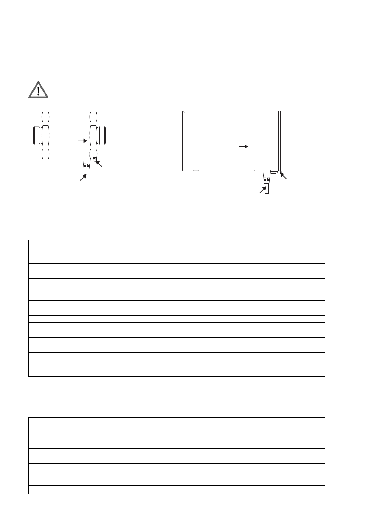
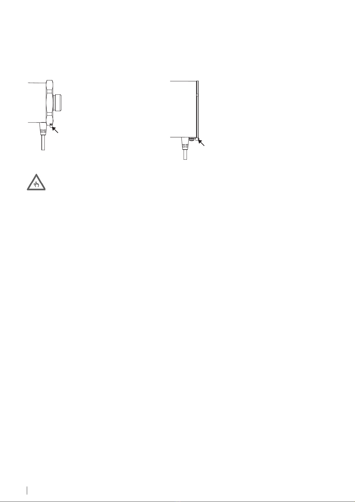
Integra AMFLO MAG Smart Service manual

VD 6-805 def 10.2017
Montage- und Bedienungsanleitung Seite 2 - 8
Mounting and operating instructions Page 9 - 15
Instructions de montage et mode d’emploi Page 16 - 24
AMFLO
®
MAG Smart
Inhaltsverzeichnis
Allgemeine Informationen 2
Technische Daten 2
Montagehinweise 5
Elektrische Installation 7
Garantie 8
Fehlerbehebung 8
EG-Konformitätserklärung 24
Table of contents
General informations 9
Technical data 9
Mounting instructions 12
Electrical installation 14
Warranty 15
Trouble shooting 15
EC declaration of conformity 24
Sommaire
Informations générales 16
Spécifications techniques 16
Instructions de montage 19
Installation électrique 21
Garantie 22
Dépannage 22
Déclaration CE de conformité 24

2AMFLO
®
MAG Smart
Allgemeine Informationen
Der AMFLO
®
MAG Smart ist als Durchflussmesser für leitfähige Flüssigkeiten konzipiert und liefert Volumenimpulse.
Bei dem Gerät handelt es sich um ein Präzisionsmessinstrument, weshalb es bei der Installation vorsichtig zu handha-
ben ist. Ein unsachgemässer Umgang kann zum Erlöschen der Garantie führen. Verwenden Sie für die Verbindung des
Gerätes mit der Leitung Messinganschlüsse.
Technische Daten
* Bitte überprüfen Sie die chemische Beständigkeit des Geräts (Messrohr, Elektroden und Dichtungen) für das eingesetzte Medium!
Messbereich (Zugelassen nach EN 1434 Klasse 2, Messdynamik 1:250)
* entspricht Standardwerten von qp nach EN 1434
Durchfluss-
richtung
Anschlussleitung
Anschluss für
Potentialausgleich
Durchfluss-
richtung
Anschlusskabel
Anschluss für
Potentialausgleich
Nennweite DN mm 15 20 25 32 40 50 65 80 100
Zoll 1/2 3/4 1 1 1/4 1 1/2 2 2 1/2 3 4
qi (Minimaldurchfluss) m
3
/h 0.012 0.02 0.028 0.048 0.08 0.12 0.2 0.32 0.48
qp (Nenndurchfluss) m
3
/h 3 5 7 12 20 30 50 80 120
qs (Maximaldurchfluss) m
3
/h 3.3 5.7 8.5 14 22 35 59 90 140
v (qi) m/s 0.019 0.018 0.016 0.017 0.018 0.017 0.017 0.018 0.017
v (qp) m/s 4.72 4.42 3.96 4.14 4.42 4.24 4.19 4.42 4.24
Δp (qp/2)* mbar 66 38 37 19 30 24 42 51 44
Flow bei Δp = 100 mbar m
3
/h 1.85 4.06 5.75 13.76 18.26 30.62 38.58 56.01 90.45
Kvs m
3
/h 5.84 12.82 18.20 43.5 57.7 96.8 122 177 286
Nennweiten DN 15 - 100
Elektroden Edelstahl 1.4571
Flüssigkeit Wasser und andere Flüssigkeiten*
Nenndruck PN 16
Liner PPE Noryl
Flansch Messing verchromt
Mantelrohr Stahl pulverbeschichtet
Dichtungen NBR/EPDM
Schutzklasse IP 67
Temperaturspanne Flüssigkeit TFluid = 0 - 60 °C
Umgebungstemperatur TAmb = 2 - 55 °C
Min. eletrische Leitfähigkeit 40 μS/cm
Genauigkeit ±0.5 % (±0.004 m/s unterhalb 0.5 m/s)
Ausgang max. 200 Hz (Pulsdauer 2.5 ms bei 200 Hz), SSR (Solid State Relais) passiv, max. 48 V / 50 mA
Messbereich 0.015 - 5 m/s
Anschlussleitung 5 m, fest verbunden
Anschluss Pulsausgang und Statusausgang
Spannungsversorgung 24 VDC, 150 mA (galvanisch getrennt)

3AMFLO
®
MAG Smart
Druckverlust
Abmessungen und Geräteanschluss
DN
a
Da
T
L
Di
DN
AF
Nennweite DN mm 15 20 25 32 40 50 65 80 100
Zoll 1/2 3/4 1 1 1/4 1 1/2 2 2 1/2 3 4
L mm 110 130 150 150 150 200 200 225 250
AF mm 67 67 67 81 86 101 121 131 156
a mm 131517------
T Zoll 3/4 1 1 1/4 Wafer Wafer Wafer Wafer Wafer Wafer
Di mm 10 13 16 21 26 32.5 42.25 52 65
Da mm 65 65 65 81 86 101 121 131 156
Gewicht kg 1.3 1.4 1.6 1.8 1.8 4.6 6.5 7.9 11
L
DN
Da
DN
Di
DN15
DN20
DN25
DN32
DN40
DN50
DN65
DN80
DN100
10
100
1000
0.00010.0010.010.11.0
Durchfluss / Flow / Débit [m³/h]
∆p [mbar]

4AMFLO
®
MAG Smart
Messfehlergrenzen
Genauigkeit
Die Messgenauigkeit des Gerätes beträgt:
±0.5 % (±0.004 m/s unterhalb von 0.5 m/s)
unter den folgenden Referenzbedingungen:
Flüssigkeitstemperatur: 20 °C
Statischer Flüssigkeitsdruck: >3 bar
Umgebungstemperatur: 23 °C
Vorwärmzeit des Gerätes: 15 min.
Flüssigkeit: Wasser
-5
-4
-3
-2
-1
0
1
2
3
4
5
00.511.522.533.544.555.5
V (m/s)
%
Nach EN 1434
AMFLO® MAG Smart
Typische Fehlerkurve

5AMFLO
®
MAG Smart
Montagehinweise
Der Durchflussmesser ist bevorzugt horizontal unter Beachtung der Durchflussrichtung einzubauen (vertikaler Einbau möglich). Die Mes-
selektroden müssen bei horizontalem Einbau waagrecht ausgerichtet werden (Anschlussleitung nach unten). Weitere Empfehlungen und
Montagebedingungen siehe nachfolgende Tabelle.
• keine Ein- und Auslaufstrecke notwendig
• keine radiale Zentrierung notwendig (maximaler Versatz 10 % vom Nenndurchmesser)
Horizontaler und vertikaler Einbau möglich
Zu vermeiden Empfehlung
Beachten Sie die Informationen auf dem Typenschild!
Die Montage des Durchfluss-
messers in langen Leitungen
ohne Abstützungen ist zu ver-
meiden.
Teilweise gefüllte Leitungen
führen zu erheblichen Messfeh-
lern und sind daher zu vermei-
den.
Grosse Anfangszwischenräume
zwischen Leitung und Durch-
flussmesser können beim An-
ziehen der Muttern zu hohen
Torsionsspannungen und Biege-
dehnungen am Gerät führen.
In Anlagen mit an das Gerät
anschliessenden langen Leitun-
gen sollten schwingungshem-
mende Anschlussstücke ver-
wendet werden.
Während des Betriebs muss die
Leitung jederzeit voll sein.
Die Zwischenräume für die
Dichtungen müssen so klein
wie möglich sein, so dass das
Gerät beim Anziehen der Mut-
tern nicht beansprucht wird.

6AMFLO
®
MAG Smart
Das Gerät muss spannungsfrei montiert werden (keine Torsions- oder Biegespannung). Gegebenenfalls sind Abstützun-
gen für die Leitung und das Gerät zu verwenden.
Das Gerät ist durch werkseitig angebrachte Siegel vor Manipulation und unbefugter Wartung geschützt. Durch unsach-
gemässe Verwendung und Montage des Gerätes werden die Siegel zerstört, was zum Erlöschen der Garantie führt.
Gewindeausführung
Beim Montieren der Anschlussverschraubungen muss mit einem zweiten Schlüssel an der anliegenden Schlüsselfläche gekontert werden.
Zum Anziehen der Überwurfmutter ist ein Drehmomentschlüssel zu verwenden. Andernfalls könnte das maximal zulässige Drehmoment
überschritten und ein werkseitig angebrachtes Siegel zerstört werden.
Richtig Falsch
Waferausführung
Für die Installation wird das Gerät zwischen zwei DIN-Flansche gemäss EN 1092 mit einem PN 16 entsprechenden Nenndruck geklemmt.
Nach der erfolgten Installation muss das System gründlich durchspült werden, um die Luft entweichen zu lassen.
Drehmoment für den Leitungsanschluss
Die erforderlichen Drehmomente für den Einbau des Gerätes an die Leitung sind der nachstehenden Tabelle zu entnehmen. Die Höchst-
werte dürfen auf keinen Fall überschritten werden. Zur Montage ist ein Drehmomentschlüssel zu verwenden.
Nennweite DN mm 15 20 25 32 40 50 65 80 100
Zoll 1/2 3/4 1 1 1/4 1 1/2 2 2 1/2 3 4
max. Drehmoment T 35 Nm 110 Nm 260 Nm 86 Nm 90 Nm 120 Nm 82 Nm 84 Nm 113 Nm
max. reine Zugkraft Fmax 18kN18kN18kN------
Druckkraft Fpmax 7 kN 7 kN 7 kN 136 kN 142 kN 189 kN 258 kN 264 kN 356 kN
F
max
F
max
T
T
Fp
max
Fp
max
1. 2. 3.

7AMFLO
®
MAG Smart
Elektrische Installation
Stromversorgung
24 VDC ±10 % (max. Strom 150 mA).
Die Stromversorgung muss galvanisch getrennt sein. Darüber hinaus dürfen die angegebenen Spannungsabweichun-
gen von ±10 % nicht überschritten werden.
Verdrahtung
Der Durchflussmesser AMFLO
®
MAG Smart wird wie folgt an einen Wärme- und Durchflusszähler angeschlossen:
Adernfarbe: Funktion:
gelb Impulsausgang
rosa Statusausgang
grün Impuls-/Statusausgang Common
braun 24 VDC (Stromversorgung)
blau GND (Stromversorgung)
Wegen möglicher Kondensation am Gerät muss die Anschlussleitung nach unten zeigen. Wenn die restliche Leitung im Bogen nach oben
geführt wird, tropft Kondensat ab.
Korrekte Installation bei horizontaler Montage:
DN 15...25 DN 32...100
Impulsausgang:
Modus: passiv (solid state relais)
max. Strom/max. Spannung: 50 mA, 48 V
Max. Ausgangsfrequenz: 200 Hz
Nennweite DN mm 15 20 25 32 40 50 65 80 100
Zoll 1/2 3/4 1 1 1/4 1 1/2 2 2 1/2 3 4
Impulswert ml 5 10 15 25 35 50 85 130 200
Durchflussrichtung
oben
unten
Durchflussrichtung
oben
unten

8AMFLO
®
MAG Smart
Potenzialausgleich
Die Messgenauigkeit des Gerätes wird durch den richtigen Potenzialausgleich sichergestellt. Hierzu ist erforderlich, dass die Spannungs-
versorgung des Gerätes galvanisch getrennt ist. Das Gerät wird durch ein Kabel mit geringem Widerstand mit einem Anschlussstück an der
seitlichen Schraube am Flansch geerdet.
Die Stromversorgung muss galvanisch isoliert sein, damit Massekreise vermieden werden.
Garantie
Die Garantie erlischt in folgenden Fällen:
- Ein werkseitig angebrachtes Siegel zwischen dem Gehäuse und den Flanschverbindungen ist zerstört.
- Das Gerät wurde geöffnet.
- Das Gerät wird für andere Zwecke verwendet als die, die in der Dokumentation angegeben sind (Anwendung, Flüssigkeit, Betriebs-
temperatur, Druck, Durchflussgeschwindigkeit, etc.).
- Das Gerät ist mit grösseren Drehmomenten, etc. montiert worden als unter “Drehmoment für den Leitungsanschluss” angegeben.
Fehlerbehebung
Die ordnungsgemässe Funktion des Gerätes kann erst festgestellt werden, wenn es an einen Wärmezähler angeschlossen und der Wär-
mezähler für das Gerät richtig konfiguriert worden ist.
Problem Mögliche Ursachen
Keine Ausgangsimpulse Ist das Gerät an die Stromversorgung angeschlossen worden?
Entspricht die Spannung den Spezifikationen?
Ist die Leitung teilgefüllt oder leer?
Liegt die Strömungsgeschwindigkeit oder Durchflussmenge ausserhalb
der Spezifikation?
Falsche Durchflussrichtung?
Sind die Elektroden verschmutzt?
Falsche Verdrahtung?
Ist die Impulsfrequenz am Wärmezähler auf 200 Hz eingestellt worden?
Instabile Messungen Ist die Durchflussmenge stabil?
Liegt die Strömungsgeschwindigkeit oder Durchflussmenge ausserhalb
der Spezifikation?
Ist der Potentialausgleich ordnungsgemäss durchgeführt?
Ist die Stromversorgung wie angegeben galvanisch getrennt?
Sind die Elektroden verschmutzt?
Ist die Leitung teilgefüllt oder leer?
Sind Gasblasen im Medium?
Anschluss für
Potentialausgleich
Anschluss für
Potentialausgleich

9AMFLO
®
MAG Smart
General informations
AMFLO
®
MAG Smart has been designed as a volumetric flow sensor for measurement of conductive fluids.
The device is a precision measuring instrument and therefore must be handled with care during installation. Incorrect
handling can lead to loss of warranty. Use brass connections for connecting the device to the pipework.
Technical data
* Please check the chemical resistance of the device (liner, electrodes and gaskets) for the used medium!
Range of measurement (approved according to EN 1434 class 2, measurement dynamic 1:250)
* equivalent to standard values of qp according to EN 1434
Flow direction
Connecting cable
Potential
equalisation
connection
Flow direction
Connecting cable
Potential
equalisation
connection
Nominal diameter DN mm 15 20 25 32 40 50 65 80 100
inch 1/2 3/4 1 1 1/4 1 1/2 2 2 1/2 3 4
qi (minimal flow) m
3
/h 0.012 0.02 0.028 0.048 0.08 0.12 0.2 0.32 0.48
qp (nominal flow) m
3
/h 3 5 7 12 20 30 50 80 120
qs (maximal flow) m
3
/h 3.3 5.7 8.5 14 22 35 59 90 140
v (qi) m/s 0.019 0.018 0.016 0.017 0.018 0.017 0.017 0.018 0.017
v (qp) m/s 4.72 4.42 3.96 4.14 4.42 4.24 4.19 4.42 4.24
Δp (qp/2)* mbar 66 38 37 19 30 24 42 51 44
Flow at Δp = 100 mbar m
3
/h 1.85 4.06 5.75 13.76 18.26 30.62 38.58 56.01 90.45
Kvs m
3
/h 5.84 12.82 18.20 43.5 57.7 96.8 122 177 286
Nominal sizes DN 15 - 100
Electrodes Stainless steel 1.4571
Fluid Water and other fluids*
Nominal pressure PN 16, JIS 10K, ANSI 150
Liner PPE Noryl
Flange Chromed brass
Outer casing Coated steel
Gaskets NBR/EPDM
Protection class IP 67
Fluid temperature range TFluid = 0 - 60 °C
Ambient temperature TAmb = 2 - 55 °C
Min. electrical conductivity 40 μS/cm
Accuracy ±0.5 % (±0.004 m/s slower than 0.5 m/s)
Digital output max. 200 Hz (pulse duration 2.5 ms at 200 Hz), SSR (Solid State Relais) passive, max. 48 V / 50 mA
Range of measurement 0.015 - 5 m/s
Cable length 5 m, fixed on sensor side
Wiring pulse and alarm outputs
Power supply 24 VDC, 150 mA (galvanically isolated)

10 AMFLO
®
MAG Smart
DN15
DN20
DN25
DN32
DN40
DN50
DN65
DN80
DN100
10
100
1000
0.00010.0010.010.11.0
Durchfluss / Flow / Débit [m³/h]
∆p [mbar]
Pressure loss
Device dimensions and connections
DN
a
Da
T
L
Di
DN
AF
L
DN
Da
DN
Di
Nominal diameter DN mm 15 20 25 32 40 50 65 80 100
inches 1/2 3/4 1 1 1/4 1 1/2 2 2 1/2 3 4
L mm 110 130 150 150 150 200 200 225 250
AF mm 67 67 67 81 86 101 121 131 156
a mm 131517------
T inches 3/4 1 1 1/4 Wafer Wafer Wafer Wafer Wafer Wafer
Di mm 10 13 16 21 26 32.5 42.25 52 65
Da mm 65 65 65 81 86 101 121 131 156
Weight kg 1.3 1.4 1.6 1.8 1.8 4.6 6.5 7.9 11

11AMFLO
®
MAG Smart
Measuring error limits
Accuracy
The measurement accuracy of the device is:
±0.5 % (±0.004 m/s slower than 0.5 m/s)
under the following reference conditions:
Fluid temperature: 20 °C
Static fluid pressure: >3 bar
Ambient temperature 23 °C
Device warm-up time 15 min.
Fluid: Water
-5
-4
-3
-2
-1
0
1
2
3
4
5
00.511.522.533.544.555.5
V (m/s)
%
According to EN 1434
AMFLO® MAG Smart
Typical error curve

12 AMFLO
®
MAG Smart
Mounting instructions
As the type plate indicates, the normal mounting position of the device is horizontal (also vertical possible) with the electrodes lying in a ho-
rizontal plane. For horizontal mounting the electrodes axis must lie in a horizontal plane (cable head pointing downwards). Conditions of
mounting are given in the table below.
• No in- and outlet section needed
• No radial centered mounting needed (max. radial position offset 10 % of diameter)
Horizontal and vertical mounting possible
Avoid Recconmended
Consult the information given on the type plate.
In installations with long pipes
connecting to the device, antivi-
bration joints should be used.
In operation, the pipe must be
completely full at all times.
The gaps provided for the ga-
skets must be as small as possi-
ble so that, when tightening the
nuts, the device is not under
strain.
Avoid installing the flow sensor in
long pipes without supports.Avo-
id vibrations.
Partially filled pipes will cause
considerable measuring errors
and must be avoided.
Large initial gaps between pipe
work and flow sensor can result
in large torsional and bending
strains on the device when tigh-
tening the nuts.

13AMFLO
®
MAG Smart
The device must be free of tension when mounted (no torsional or bending strains). If necessary pipework and device
mounting supports should be used to ensure this.
The device is protected against manipulation and unauthorized maintenance by factory seals. The seals will be broken
by incorrect handling and mounting of the device, leading to immediate forfeiture of the warranty.
Version with threaded connections
The devices are fixed to the pipework with the aid of two spanners. The devices are provided with seatings of 65 mm at the two ends so
that they can be held rigidly in position with the first spanner. The second spanner (preferably a torque wrench) is used to tighten the con-
necting nut to the device. During this operation, both spanners must be mounted on the same side of the device as illustrated below other-
wise the maximum permissable torque could be exceeded and a factory seal destroyed.
Correct Incorrect
Wafer version
For the installation, the device is clamped between two DIN-flanges according to EN 1092 with nominal pressure corresponding to PN 16.
Once the installation has been completed, the system must be thouroughly flushed to remove air.
Pipework connecting torques
The required connecting (tightening) torques of the device to the pipework are given in the following table. Under no circumstances are the
maximum values to be exceeded. A torque wrench should be used to ensure correct torques.
F
max
F
max
T
T
Fp
max
Fp
max
Nominal diameter DN mm 15 20 25 32 40 50 65 80 100
inches 1/2 3/4 1 1 1/4 1 1/2 2 2 1/2 3 4
Max. torque T 35 Nm 110 Nm 260 Nm 86 Nm 90 Nm 120 Nm 82 Nm 84 Nm 113 Nm
Tractive force Fmax 18kN18kN18kN------
Compressive force Fpmax 7 kN 7 kN 7 kN 136 kN 142 kN 189 kN 258 kN 264 kN 356 kN
1. 2. 3.

14 AMFLO
®
MAG Smart
Electrical installation
Power supply
24 VDC ±10 % (max. current 150 mA).
The power supply must be galvanically isolated. Furthermore the specified voltage deviations of ±10 % must not be
exceeded.
Wiring
The AMFLO
®
MAG Smart flow sensor is connected to a heat or flow meter as follows:
Wire colour: Function:
yellow pulse output
pink status output
green pulse/status output Common
brown 24 VDC (supply)
blue GND (supply)
Because of possible water condensation on the device, the system cable head must be positioned to point downwards. With the rest of the
cable leading upwards, condensation flowing to the heat meter is avoided.
Correct installation for horizontal mounting:
DN 15...25 DN 32...100
Pulse output:
Mode: passive (solid state relais)
Max. current/max. voltage: 50 mA, 48 V
Max. output frequency: 200 Hz
Nominal diameter DN mm 15 20 25 32 40 50 65 80 100
inches 1/2 3/4 1 1 1/4 1 1/2 2 2 1/2 3 4
Pulse value ml 5 10 15 25 35 50 85 130 200
Flow direction
top
bottom
Flow direction
top
bottom

15AMFLO
®
MAG Smart
Potential equalisation
The measuring accuracy of the device is assured by proper potential equalization. For this purpose it is necassary that the device power
supply is galvanically isolated. The device is grounded to a suitable grounding point by means of a low resistance cable with a lug connec-
ted to the lateral screw on the flange.
The power supply must be galvanically isolated to prevent ground loops.
Warranty
The warranty ceases in the following cases:
- A factory seal between the casing and flange connections is broken.
- The device has been opened.
- The device is used for purposes other than those specified in the documentation (application, fluid, operating temperature, pressure,
flow velocity, etc.).
- The device has been mounted with torques, etc. greater than those specified in “Pipework connecting torques”.
Trouble shooting
The correct functioning of the device can only be determined after it has been connected to a heat meter and the heat meter has been cor-
rectly configured for the device
Problem Possible causes
No output volume pulses Has the device been connected to the power supply?
Does the voltage correspond to the specifications?
Is the pipework partially filled or empty?
Is there flow?
Is the flow velocity or the flow rate outside the specification?
Is the flow rate below the cutoff value?
Has the device been mounted in the right direction?
Are the electrodes dirty?
Is the electrical wiring correct?
Has the pulse frequency been set to 200 Hz in the heat or flow meter?
Unstable measurements Is the actual flow rate stable?
Is the flow velocity or flow rate outside the specification?
Is the device properly grounded?
Is the voltage supply galvanically isolated as specified?
Are the electrodes dirty?
Is the pipework only partially full?
Are gas bubbles in the pipework?
Potential
equalisation
connection Potential
equalisation
connection

16 AMFLO
®
MAG Smart
Informations générales
Le débitmètre volumétrique AMFLO
®
MAG Smart a été conçu pour la mesure de fluides conducteurs.
Cet appareil est un instrument de mesure de précision et doit par conséquent être manipulé avec précautions lors de
l’installation. Une manipulation incorrecte peut entraîner l’invalidation de la garantie. Utilisez des raccords en laiton
pour le raccordement de l’appareil à la tuyauterie.
Spécifications techniques
* Veuillez vous assurer de la résistance chimique des matériaux du débitmètre (revêtement, electrodes et joints) en contact avec votre fluide.
Plage de mesure (homologué selon EN 1434 Classe 2, plage dynamique 1:250)
* pour des valeurs standards de qp homologuées selon EN 1434
Sens
d‘écoulement
Câble de
raccordement
Borne
de terre
Sens
d‘écoulement
Câble de
raccordement
Borne
de terre
Nennweite DN mm 15 20 25 32 40 50 65 80 100
pouces 1/2 3/4 1 1 1/4 1 1/2 2 2 1/2 3 4
qi (débit minimal) m
3
/h 0.012 0.02 0.028 0.048 0.08 0.12 0.2 0.32 0.48
qp (debit nominal) m
3
/h 3 5 7 12 20 30 50 80 120
qs (debit maximal) m
3
/h 3.3 5.7 8.5 14 22 35 59 90 140
v (qi) m/s 0.019 0.018 0.016 0.017 0.018 0.017 0.017 0.018 0.017
v (qp) m/s 4.72 4.42 3.96 4.14 4.42 4.24 4.19 4.42 4.24
Δp (qp/2)* mbar 66 38 37 19 30 24 42 51 44
Débit à Δp = 100 mbar m
3
/h 1.85 4.06 5.75 13.76 18.26 30.62 38.58 56.01 90.45
Kvs m
3
/h 5.84 12.82 18.20 43.5 57.7 96.8 122 177 286
Diamètres nominaux DN 15 - 100
Electrodes Acier inoxydable 1.4571
Fluide Eau et autres fluides*
Pressions nominales PN 16, JIS 10K, ANSI 150
Revêtement PPE Noryl
Bride Laiton chromé
Tube extérieur Acier thermolaqué
Joints NBR/EPDM
Classe de protection IP 67
Plage de temp. de fluide TFluid = 0 - 60 °C
Température ambiante TAmb = 2 - 55 °C
Conductivité électr. min. 40 μS/cm
Précision ±0.5 % (±0.004 m/s en-dessous 0.5 m/s)
Sortie numérique max. 200 Hz (durée d’impulsion 2.5 ms à 200 Hz), SSR (Solid State Relais) passive, max. 48 V / 50 mA
Plage de mesure 0.015 - 5 m/s
Longueur de câble 5 m, fixe côté capteur
Sortie sortie impulsions et sortie état
Alimentation 24 VDC, 150 mA (galvaniquement séparée)

17AMFLO
®
MAG Smart
DN15
DN20
DN25
DN32
DN40
DN50
DN65
DN80
DN100
10
100
1000
0.00010.0010.010.11.0
Durchfluss / Flow / Débit [m³/h]
∆p [mbar]
Perte de charge
Dimensions et connexions de l’appareil
DN
a
Da
T
L
Di
DN
AF
Diamètre nominal DN mm 15 20 25 32 40 50 65 80 100
pouces 1/2 3/4 1 1 1/4 1 1/2 2 2 1/2 3 4
L mm 110 130 150 150 150 200 200 225 250
AF mm 67 67 67 81 86 101 121 131 156
a mm 131517------
T pouces 3/4 1 1 1/4 Wafer Wafer Wafer Wafer Wafer Wafer
Di mm 10 13 16 21 26 32.5 42.25 52 65
Da mm 65 65 65 81 86 101 121 131 156
Poids kg 1.3 1.4 1.6 1.8 1.8 4.6 6.5 7.9 11
L
DN
Da
DN
Di

18 AMFLO
®
MAG Smart
Tolérance de mesure
Précision
La précision de mesure de l’appareil est de :
±0.5 % (±0.004 m/s en-dessous 0.5 m/s)
dans les conditions de référence suivantes :
Température de fluide : 20 °C
Pression de fluide statique : >3 bar
Température ambiante: 23 °C
Temps de préchauffage de l’appareil: 15 min.
Fluide: Eau
-5
-4
-3
-2
-1
0
1
2
3
4
5
00.511.522.533.544.555.5
V (m/s)
%
Selon EN 1434
AMFLO® MAG Smart
Courbe d’erreur typique

19AMFLO
®
MAG Smart
Instructions de montage
Comme l’indique la plaquette signalétique, la position de montage normale de l’appareil est à l’horizontale (position verticale également
possible), avec les électrodes disposées sur un plan horizontal (connection du câble électrique dirigée vers le bas). De plus amples infor-
mations sur les conditions de montage sont présentées dans le tableau ci-dessous.
• Pas de tuyau droit en amont et en aval nécessaire
• Pas de centrage radial nécessaire (Décalage maximal 10 % du diamètre nominal)
Possibilité de montage horizontal et vertical
A éviter Recommandé
Consultez les informations mentionnées sur la plaquette signalétique.
Eviter d’installer le débitmètre
sur de longs tuyaux sans sup-
ports.
Les tuyaux partiellement remplis
peuvent provoquer des erreurs
de mesure considérables et doi-
vent être évités.
Un interstice important entre la
tuy. et le débitm. peut entraîner
d’importantes contraintes de tor-
sion et de flexion sur l’app. lors
du serrage des écrous.
Dans des installations avec de
longs tuyaux raccordés à l’ap-
pareil, il convient d’utiliser des
join antivibration.
En mode opérationnel, le tuyauy
doit en permanence être com-
plètement rempli.
Les interstices prévus pour les
joints doivent être aussi faibles
que possible de façon à ce que
l’app. ne soit soumis à aucune
contrainte lors du serrage des
écrous.

20 AMFLO
®
MAG Smart
L’appareil monté ne peut être soumis à des tensions (pas de contraintes de torsion ni de flexion). Utiliser si nécessaire
des supports de montage pour la tuyauterie et l’appareil.
L’appareil est protégé contre toute erreur de manipulation au moyen de sceaux d’usine. En cas de manipulation et de
travaux de maintenance non autorisés, les sceaux se brisent, entraînant l’invalidation immédiate de la garantie.
Appareils avec raccords filetés
Les appareils sont fixés à la tuyauterie à l’aide de deux clés. Les appareils sont fournis avec des portages d’étanchéité de 65 mm aux deux
extrémités de façon à ce qu’ils puissent être solidement maintenus en position avec la première clé. La seconde clé (de préférence une clé
dynamométrique) est utilisée pour serrer l’écrou de fixation sur l’appareil. Durant cette opération, les deux clés doivent être positionnées
du même côté de l’appareil comme illustré ci-dessous, faute de quoi le couple de serrage maximum admissible pourrait être dépassé, ce
qui risquerait de briser un sceau d’usine.
Correcte Incorrecte
Appareils avec raccords sans brides - Wafer
Pour l’installation, l’appareil est serré entre deux brides DIN suivant EN 1092 avec une pression nominale correspondant à PN16.
Lorsque l’installation est terminée, le système doit être soigneusement rincé afin de chasser tout l’air qu’il contient.
Couples de serrage des raccords de tuyauteries
Les couples de serrage requis de l’appareil sur la tuyauterie sont indiqués dans le tableau suivant. Les valeurs maximales ne peuvent en
aucun cas être dépassées. Utilisez une clé dynamométrique pour garantir un serrage aux couples corrects.
F
max
F
max
T
T
Fp
max
Fp
max
Diamètre nominal DN mm 15 20 25 32 40 50 65 80 100
pouces 1/2 3/4 1 1 1/4 1 1/2 2 2 1/2 3 4
Couple max. T 35 Nm 110 Nm 260 Nm 86 Nm 90 Nm 120 Nm 82 Nm 84 Nm 113 Nm
Force de traction pure max. Fmax 18kN18kN18kN------
Force de serrage Fpmax 7 kN 7 kN 7 kN 136 kN 142 kN 189 kN 258 kN 264 kN 356 kN
1. 2. 3.
Table of contents
Languages:
Popular Accessories manuals by other brands

Craftsman
Craftsman 316.792420 Operator's manual

Maxcess
Maxcess CL Series instruction manual

Micro Detectors
Micro Detectors CR0 Series Installation and operation manual

MYDLINK
MYDLINK DCH-S161 quick start guide

Makita
Makita DCW180 instruction manual

Online Electronics
Online Electronics 4003 MAGSIG operating manual